Heterodyne detection of guided waves using a ... - OSA Publishing
Recommend Documents
Jul 11, 2005 - in a planar waveguide splitter by near-field optical phase imaging,â .... modulation with lock-in detection, demodulation at high harmonics of the ...
gain trans-impedance amplifier (DLPCA-200, FEMTO) and a lock-in amplifier (SRS830,. Stanford Research Systems) are used for high dynamic range.
R. C. Quenelle, âNonlinearity in interferometer measurements,â Hewlett Packard J. 34, 10 (1983). 15. N. Bobroff, âRecent advances in displacement measuring ...
an optically compensation bend by using the heterodyne interferometry,â in ... demodulation that is to directly count the Doppler-shift frequency to measure ...
n/T Measurements performed with guided waves and their application to the temperature sensitivity of wavelength-division multiplexing filters. Emmanuel ...
Feb 20, 2006 - Abstract: One of the main drawbacks of Fourier domain optical coherence ... N. A. Nassif, B. Cense, B. H. Park, M. C. Pierce, S. H. Yun, B. E. ...
J. F. Nye, Physical Properties of Crystals (Oxford University Press, Oxford, 1957), pp. .... crystal plate with different velocities are two elliptically polarized waves.
and high phase sensitivity, which is limited only by the signal-to-noise ratio (SNR) of the amplitude measurement. Using free-running lasers for. THz wave ...
P. McNamara, S. Vitale, K. Danzmann, and on behalf of the LISA Pathfinder ... J. Miller, S. Ngo, A. J. Mullavey, B. J. J. Slagmolen, D. A. Shaddock, and D. E. ...
Aug 10, 2010 - Barker and Hollenbach demonstrated LDV normally reflected from ..... (1964). 5. J. W. Forman, Jr., E. W. George, and R. D. Lewis, âMeasure-.
Mar 9, 2015 - tutorial the construction of an LDV detector and the demodulation ... The wave vector, k, is a vector describing the propagation of the wave, where ⣠â£= ..... The detected waveforms are then compared to a state-of-the-art LDV.
Feb 20, 2006 - Adrian H. Bachmanna), Rainer A. Leitgeb a,b), Theo Lasser a) ... A. F. Fercher, W. Drexler, C. K. Hitzenberger, T. Lasser,âOptical coherence ...
R. Quenelle, Hewlett Packard J. 34, 10 (1983). 8. C. Sutton, J. Phys. E 20, 1290 (1987). 9. W. Hou and G. Wilkening, Precis. Eng. 14, 91 (1992). 10. C. Wu and ...
Jun 7, 2017 - units moved by two separate linear stages along x-axis and y-axis are used to ... movement of the measured stage so that the simultaneous ...
Y. Yasuno, S. Makita, T. Endo, G. Aoki, M. Itoh, and T. Yatagai, âSimultaneous B-M-mode .... frequency swept laser and high bandwidth detector (swept-source, ...
2CREOL/College of Optics, University of Central Florida, Orlando, Florida 32816, USA. *Corresponding author: [email protected]. Received August 26, 2010; ...
may be a typical application of the TGM [4,5]. It has been shown that the sample arrangement becomes more flexible if PB is taken out from the interferometer ...
A novel approach, named guided conversion enhancement, has been established to improve the laser- induced breakdown spectroscopy (LIBS) sensitivity of ...
A. E. Serebryannikov, A. O. Cakmak, and E. Ozbay, âMultichannel optical diode with unidirectional diffraction relevant total transmission,â Opt. Express 20(14), ...
Ultrasonic; guided waves; dispersion; modes; submerged plates; ... inspection, magnetic flux leakage technique, pressure testing, magnetic resonance imagery, ...
Jul 15, 2004 - J. Alton, H. E. Beere, E. H. Linfield, D. A. Ritchie, and S. Withington. Cavendish Laboratory, University of Cambridge, Madingley Road, ...
Heterodyne detection of guided waves using a ... - OSA Publishing
Jul 11, 2005 - 12 Rue Marie Curie â BP 2060, F-10010 Troyes Cedex, France ... R. Bachelot, P. Gleyzes and A.C. Boccara, âNear-field optical microscope ...
Heterodyne detection of guided waves using a scattering-type Scanning Near-Field Optical Microscope Ilan Stefanon, Sylvain Blaize, Aurélien Bruyant, Sébastien Aubert, Gilles Lerondel, Renaud Bachelot, and Pascal Royer Laboratoire de Nanotechnologie et d’Instrumentation Optique Centre National de la Recherche Scientifique –CNRS, FRE 2671, Université de Technologie de Troyes, 12 Rue Marie Curie – BP 2060, F-10010 Troyes Cedex, France Tel: +33-(0)3-25-71-84-30; Fax: +33-(0)3-25-71-84-56 [email protected]
B. Hecht, B. Sick, U.P. Wild, V. Deckert, R. Zenobi, O.J.F Martin and D.W. Pohl, “Scanning near-field microscopy with aperture probes: Fundamentals and applications,” J. of Chem. Phys. 112, 7761-7774 (2000). S. Bourzeix, J.M. Moisson, F. Mignard, F. Barthe, A.C. Boccara, C. Licoppe, B. Mersali, M. Allovon, ans A. Bruno, “Near-field optical imaging of light propagation in semiconductor waveguide structures,” Appl. Phys. Lett. 73, 1035-1037 (1998). M.L.M. Balistreri, D.J.W. Klunder, F.C. Blom, A. Driessen, H.W.J.M. Hoekstra, J.P. Korterik, L. Kuipers, and N.F. van Hulst “ Visualizing the whispering gallery modes in a cylindrical optical microcavity,” Optics Letters 24, 1829-1831 (1999). M.L.M Balistreri,J.P. Korterik, L. Kuipers, and N.F. van Hulst, N.F. “Visualization of mode transformation in a planar waveguide splitter by near-field optical phase imaging,” Appl. Phys. Lett. 79, 910-912 (2001). A.L. Campillo, J.W.P. Hsu, C.A. White, and C.D.W. Jones, “Direct measurement of the guided modes in LiNbO3 waveguides,” Appl. Phys. Lett. 80, 2239-2241 (2002). M.L.M. Balistreri, H. Gersen, J.P. Korterik, L. Kuipers and N.F. van Hulst, ”Tracking femtosecond laser pulses in space and time,” Science 294, 1080–1082 (2001). H. Gersen, J. P. Korterik, N. F. van Hulst, and L. Kuipers, “Tracking ultrashort pulses through dispersive media: Experiment and theory,” Phys. Rev. E 68, 026604 (2003). R. Bachelot, P. Gleyzes and A.C. Boccara, “Near-field optical microscope based on local perturbation of a diffraction spot,” Opt. Lett. 20, 1924–1926 (1995). Y. Inouye and S. Kawata, “Near-field scanning optical microscope with a metallic probe tip,” Opt. Lett. 19, 159 -161 (1994). F. Zenhaursen, M.P. O’Boyle, and H.K. Wickramasinghe, Phys. Lett. 65, 1623 (1994). S. Blaize S. Aubert, A. Bruyant, R. Bachelot, G. Lerondel, P. Royer, J.-E. Broquin and V. Minier, “Apertureless scanning near-field optical microscopy for ion exchanged channel waveguide characterization,” Journal of Microscopy 209, 155–161 (2003). R. Bachelot, G. Lerondel, S. Blaize, S. Aubert, A. Bruyant, and P. Royer, “Probing photonic and optoelectronic structures by apertureless scanning near-field optical microscopy,” Microscopy Research and Technique 64, 441–452 (2004). R. S. Taylor, K.E. Leopold, M. Wendman, G. Gurley, and V. Elings, “Scanning probe optical microscopy of evanescent fields,’’ Rev. Sci. Instrum. 69, 2981–2987 (1998).
#7751 - $15.00 USD
(C) 2005 OSA
Received 8 June 2005; revised 3 July 2005; accepted 4 July 2005
14. S. Aubert, A. Bruyant S. Blaize, R. Bachelot, G. Lerondel, S. Hudlet, and P. Royer, ”Analysis of the interferometric effect of the background light in apertureless scanning near-.eld optical microscopy,” J. Opt. Soc. Am. B 20, 2117–2124 (2003). 15. G. Wurtz, R. Bachelot and P. Royer, “Imaging a GaAlAs laserdiode in operation using apertureless scanning near-field optical microscopy,” Eur. Phys. J.: Appl. Phys. 5, 269–275 (1999). 16. R. Hillenbrand, B. Knoll, and F. Keilmann, “Pure optical contrast in scattering-type scanning near-field microscopy,” J. Microsc. (Oxford) 202, 77–83 (2000). 17. R. Hillenbrand, T. Taubner, and F. Keilmann, “Phonon enhanced light matter interaction at the nanometre scale,” Nature 418, 159–162 (2002). 18. E.J. Sanchez, L. Novotny, and. X.S. Xie, “Near-field fluorescence microscopy based on two-photon excitation with metal tips,” Phys. Rev. Lett. 82, 4014–4017 (1999). 19. J.-E. Broquin, “Ion Exchange integrated devices,” in Integrated Optics Devices V, Giancarlo and C. Righini, eds., Proc. SPIE, 4277, 105-115 (2001). 20. A. Nesci, R. Dandliker, H.P. Herzig , “Quantitative amplitude and phase measurement by use of a heterodyne scanning near-field optical microscope,” Opt. Lett. 26, 208–210 (2001). 21. A. Bruyant, I. Stefanon, G. Lerondel, S. Blaize, S. Aubert, R. Bachelot, P. Royer, P. Pirasteh, J. Charrier, and P. Joubert, “light propagation in porous silicon waveguide : an optical modes analysis in near field,” phys. stat. sol. (a) 202, No. 8, 1417–1421 (2005)
1. Introduction Advances in integrated optics require new characterization techniques. In particular, the mapping of optical field propagation in confined waveguiding structures is very important for a comprehensive understanding of these structures design. The evanescent nature of the field outside these structures makes the direct observation of the propagating light impossible with conventional microscopy except when strong scattering losses occur. This explains the huge effort made during last decade in the development of Scanning Near Field Optical Microscopy (SNOM) for photonic devices characterization. With a subwavelength resolution scale, SNOM allows non destructive investigations of the optical guided field. This technique is based on the probing of evanescent waves by scanning a nanometric tip in the vicinity of a sample surface. There are currently two main classes of SNOM probes. The first uses optical fibres; for example, a metal-coated tapered optical fibre [1] is used to pick up the light from the nearfield region of the studied structures. The light is coupled to the fibre and detected at the other fibre extremity. This technique has been applied successfully to observe the optical field propagation in various confined waveguiding structures with a subwavelength resolution. Conventional detection with a quadratic detector leads to the intensity mapping of the propagated optical field [2-3], whereas homodyne or heterodyne interferometric detection leads to the complex optical field mapping (amplitude and phase) [4-5]. Time-resolved SNOM measurements using interferometric setups have also been reported [6-7]. The alternative approach is based on the use of an apertureless sharp dielectric or metal tip, acting as a scattering centre in the near-field region [8-10].The radiated field emitted by the tip end is collected by an external optical detection system. This configuration is called either apertureless-SNOM (ASNOM) or scattering SNOM (s-SNOM). The s-SNOM probe seems to arouse an increasing interest in the SNOM community for numerous advantages compared to the aperture probe : easiness of tip design and fabrication, tip robustness, high resolving power (related to the tip diameter), high level of collected signal, achromatic behaviour (conventional tapered fibre probes present a wavelength cutoff effect ), polarisation sensitivity [11-12]. However, in s-SNOM, the use of external far-field detection entails several difficulties: other fields than the field scattered by the tip end have to be taken into account, such as the background light corresponding, for example in the case of waveguides, to the scattered propagation losses (Fig. 1). Numerous authors have stated that the background field cannot be fully suppressed because of the coherent adding of the different collected fields [13]. The intrinsic interferometric nature of the s-SNOM signal when the background field acts as a reference field has been investigated in detail in a previous paper [14].
#7751 - $15.00 USD
(C) 2005 OSA
Received 8 June 2005; revised 3 July 2005; accepted 4 July 2005
The main consequence is the appearance of tilted fringes which result from interference between the field scattered by the probe and a scattered background field in the direction of detection. In particular we have experimentally shown that the s-SNOM signal can describe either the field intensity or the complex field amplitude depending on the sample structures surrounding the tip. The resulting image is the mix of intensity, amplitude and phase signals [14]. One crucial issue for s-SNOM is thus related to the control of the coherent background field. Several methods have been proposed to extract the weak signal issued from the local interaction between the tip end and the sample. Among them are tip-to-sample distance modulation with lock-in detection, demodulation at high harmonics of the modulation frequency [15], heterodyne detection [16-17] and excitation of a local field singularity at the tip apex [18]. In many experiments, these methods have permitted the extraction of near-field components in the presence of a strong background field.
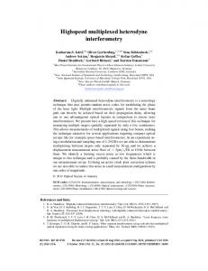
Fig. 1. s-SNOM detection scheme. The external detection involves the collection of the scattering field from the tip and a background field provided by various scattering centers such as dusts or defects.
Following Hillenbrand et al. [16] who recommends for the first time the idea of combining an s-SNOM with a heterodyne interferometer, we propose to take advantage of this setup for the characterisation of optical integrated waveguides. We will show in this paper that the use of a mach-zehnder heterodyne interferometer allows us to get rid of the coherent background field adding. Heterodyne detection offers also an elegant way to increase the electronic signal for a given object power: the signal to noise ratio will be increased up to a point where shot noise will dominate the Johnson noise from the detector. Furthermore, heterodyne allows us to measure the complex amplitude (real amplitude and phase) of the waveguide near field signal. The paper is organised in three parts: first we will present the experimental setup. Next, we will give a complete analysis of the provided signal with the support of experimental data. Finally, we will present an experimental characterisation of a highly confined refracted waveguide realised using the silicon photonic technology based on silicon on insulator (SOI) substrates. 2. Experimental The experimental setup is sketched in Fig. 2. It is based on a fibre Mach-Zehnder interferometer. After splitting of a laser diode beam (frequency ω/2π = 1.9 1014 Hz ) by a fibre coupler (ratio 90/10%), a reference beam at frequency ω+∆ω is generated by two crossed #7751 - $15.00 USD
(C) 2005 OSA
Received 8 June 2005; revised 3 July 2005; accepted 4 July 2005
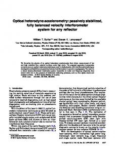
acousto-optic shifters (AO shifters). The optical shift ∆ω can be set from 10 kHz to a few MHz. In the other arm, the object beam (frequency ω) is launched into the optical chip after a polarisation control. On the waveguide surface, the local guided field (evanescent tails of the guided modes and eventually radiated fields) is converted into radiating modes by a silicon tip for AFM (Atomic Force Microscopy). The tip to surface distance is controlled by the AFM in intermittentcontact mode (also called “tapping mode”). In this mode the probe oscillates along the z direction, perpendicularly to the sample usually at a frequency closed to ω0/2π ≈ 300 kHz and with amplitude around 100 nm. The device under test is mounted on an x-y piezoelectric stage and is scanned beneath the AFM probe. The atomic force feedback ensures constant vibration amplitude during the scan acquisition and leads to a precise topography image. Simultaneously, the light scattered by the nano-probe is collected by a confocal-type microscope. More details on the optical collection system can be found elsewhere [14-15]. Finally, the object beam and the reference beam are combined in a single mode fibre coupler and detected by a standard photodiode detector (Hamamatsu InGaAs photodiode). In order to extract both the amplitude and phase of the local optical field, the photocurrent is demodulated by a dual output lock-in amplifier (Perkin Elmer 7280). It is worth noting that in such a setup the light source can be a coherent laser, or alternatively low coherence sources such as black bodies or pulsed lasers. The coherence length of the source is not a limit for the heterodyne process provided that the two arms in the interferometer have same optical lengths. In the next section a complete description of the provided signal is presented and discussed with the support of experimental data.
Fig. 2. Experimental setup. The s-SNOM is a combination of an Atomic Force Microscope (AFM) with a confocal optical microscope. The complex amplitude of the guided field is obtained by incorporating the s-SNOM into one arm of an heterodyne mach-zehnder interferometer (see text for details).
#7751 - $15.00 USD
(C) 2005 OSA
Received 8 June 2005; revised 3 July 2005; accepted 4 July 2005
3. Heterodyne s-SNOM signal Assuming a vertical cosine vibration of the probe around a mean position z0, with amplitude A, the position of the probe end can be written as
z (t ) = z0 + A cos (ω0t ) In the case of the AFM tapping mode, z0 = A so that (1) z (t ) = A + A cos (ω 0t ) With an underlying hypothesis of a vertical confined field and a passive probe (the probe does not perturb the near-field), the electric field scattered by the probe can be written analytically: E p (t ) = E p e
j ( ω t +ϕ p )
e
jγ z ( t )
up
(2)
Where •
E p ( rscan ) and ϕ p (rscan ) are respectively the local amplitude and phase of the guided
optical field at the waveguide surface at the scanner position defined by the Cartesian coordinates ( rscan , z = 0 ). •
u p is an unitary vector directed along the direction of the polarisation of the electric
field •
γ can be the imaginary transverse optical constant of a guided mode, related to the 2π neff ⎛ 4π 2 2 ⎞ . effective index neff by γ = ⎜ 2 − β ⎟ with β = λ ⎝ λ ⎠ 1/ 2
The lock-in demodulation can extract the harmonics of the detected signal, thus it is useful to develop e e
jγ z ( t )
=e
−γ A
jγ z ( t )
in Fourier series:
∑ I ( γ A)e
jnω 0 t
n
n∈
=e
−γ A
⎛ ⎝
= ⎜ I0 ( γ A) + 2
⎞ ∑ I ( γ A ) cos ( nω t ) ⎟ n
*
n∈
0
⎠
∑ I ( γ A ) cos ( nω t ) n
0
n∈
Where I n = I − n are the modified Bessel functions of the first kind. One obtains a new expression for the complex field scattered by the probe: E p (t ) = E p e
j ( ω t +ϕ p )
e
−γ A
∑ I ( γ A ) cos ( nω t ) u n
0
p
n∈
As mentioned in the introduction, the field collected by the external detection also contains a background field E Bg = E Bg e
j ( ω t + ϕ Bg )
u Bg produced by propagation losses in the
waveguide. The radiated field E Bg consists of scattered waves which propagate directly toward the detector, and thus, are not modulated by the probe (independent from the tip height modulation). In other words, all undesirable propagating waves which are not diffracted by the probe compose this background. The total electric field after combination into the fibre coupler is the sum of three terms:
#7751 - $15.00 USD
(C) 2005 OSA
Received 8 June 2005; revised 3 July 2005; accepted 4 July 2005
Finally the detected intensity on the quadratic detector is given by: I (t ) = E Bg + E ref + E p
2
(4)
Using equations (2), we obtain:
I (t ) = I
hom
(t ) + I ( t ) het
(5)
with I
hom
(t ) = E Bg + E p e 2
+ Ep e 2
−2 γ A
∑I n∈
2
n
−2 γ A
I 0 (2 γ A) + 2 E p E Bg u p ⋅ u Bg e
(2 γ A) cos( nω 0 t ) + 2 E p E Bg u p ⋅ u Bg e
−γ A
−γ A
cos (ϕ p − ϕ Bg ) I 0 ( γ A )
cos (ϕ p − ϕ Bg )
*
(6a)
∑ I ( γ A ) cos ( nω t ) (6b) n
n∈
0
*
and I (t ) = Eref het
2
(7a)
+2Eref E Bg u ref ⋅ u Bg cos ( ∆ω t + ϕ Bg − ϕ ref +2 E p Eref u p ⋅ u ref e
−γ A
+2 E p Eref u p ⋅ u ref e
−γ A
)
(7b)
I 0 ( γ A) cos ( ∆ω t + ϕ p − ϕ ref
∑I n∈
n
)
(7c)
( γ A) cos ( ( ∆ω + nω 0 ) t + ϕ p − ϕ ref
)
(7d)
*
A complete identification of the harmonics contained in the modulated photocurrent is obtained: •
constant term (not modulated) : (6a) and (7a)
•
harmonics at the probe vibration frequencies, nω 0
•
harmonics at the AO shift frequency, ∆ω : (7b) and (7c)
•
harmonics at the beating frequency, ∆ω + nω 0
It is worth noting that the I
hom
(n ∈
(n ∈
*
*
) : (6b)
) : (7d)
term would be the signal given by the s-SNOM with a het
direct detection (without any reference), whereas the I term is the contribution resulting from the adding of a reference arm to the setup. The constant terms (6a) and (7a) are not considered here for lack of physical interest since they can not lead to amplitude and phase extraction, and the three fields of interest (reference, background and the probe) are obviously mixed together. In the next sub-sections, we will discuss physically the nature of the modulated terms and their implication on the s-SNOM image formation process when a Lock-in amplifier demodulation is used. The argumentation is made on the support of experimental data recorded above 2D confined optical waveguides realised by ions exchange on planar glass substrate. The wavelength of illumination has been set to 1.55µm, which corresponds to a single mode propagation. Figure 4(A) is the AFM image showing the topography of the waveguide surface. More details on the structure can be found in Ref. [19].
#7751 - $15.00 USD
(C) 2005 OSA
Received 8 June 2005; revised 3 July 2005; accepted 4 July 2005
3.1 Lock-in detection at frequency nω 0 With lock-in demodulation at the probe oscillation frequencies, nω 0 , with n ∈ , the involved signal harmonics are retrieved from the term (6b). The amplitude of the signal through the lock-in is hence: *
Rnω (rscan ) = E p e 2
−2 γ A
0
I n (2 A γ ) + 2 E p EBg u p ⋅ u Bg e
−γ A
cos (ϕ p − ϕ Bg ) I n ( γ A )
(8)
It is clear that in addition to the intensity signal related to the probe (and the guided wave), a homodyne interferometric signal is also detected. Let us now express ϕ p − ϕ Bg as a function of the probe position ( rscan , z = 0 ) in the sample plane. This phase shift is a phase difference between the collected fields E Bg and E p . The phases of both fields change on the detector plane during the scan. On one hand, the undesirable scatters in the collection zone (small dusts for example) follow the sample motion. For example the optical path of E Bg in air increases if the sample is scanned away from the collecting objective. The phase variation of E Bg is k d irscan , where rscan is the probe position relatively to the sample and where k d corresponds to the average
wave vector of both collected fields E Bg and E p towards the microscope objective. On the other hand, as the sample is scanned under the tip apex, the phase of the scattered field E p changes according to the phase of the local guided field. However the distance between the tip and the objective remains constant. For a single guided mode of propagating constant β , the phase variation of E p is hence: β irscan . Considering the two contributions, the phase shift is given by:
ϕ p − ϕ Bg = ( β − k d )irscan (9) The local phase variation of the field scattered by the tip is hence converted to amplitude modulation, and the related phase shift [Eq. (9)] leads to oblique fringes appearing on the experimental images [Figs. 3(B) and 4(B)]. Further details about the s-SNOM signal demodulation at the vertical frequency of the probe, and in the case of an evanescent decaying mode have been previously published in Ref. [14]. 3.2 Lock-in detection at ∆ω If a lock-in detection at the AO shift frequency ∆ω is used, the involved terms in the modulated intensity are given by Eqs. (7b) and (7c):
2Eref EBg u ref ⋅ u Bg cos ( ∆ω t + ϕ Bg − ϕ ref ) + 2 E p Eref u p ⋅ u ref e
We can conclude that the presence of three fields mixed together prevents from an easy extraction of any relevant physical parameter since the phase information is coded into the demodulated amplitude.
Fig. 3. s-SNOM signal demodulated at vertical probe oscillation frequency. The studied sample is an ion exchanged integrated waveguide. (A) Scheme of s-SNOM detection. β is the guided wave vector, kd corresponds to the average wave vector of both collected fields EBg and Ep towards the microscope objective. (B) s-SNOM raw optical image. Tilted fringes appear due to a coherent adding between the field scattered by the probe and a background field scattered in the direction of detection.
This is not true anymore when E Bg is negligible compared to E p . In this case, the remaining term in the modulated intensity is: 2 E p Eref u p ⋅ u ref e
−γ A
I 0 ( γ A) cos ( ∆ω t + ϕ p − ϕ ref ) = R∆ω cos( ∆ω t + φ ∆ω )
(11)
So that the amplitude output from the lock-in leads to a signal proportional to E p , and the phase output leads to ϕ p , since ϕ ref being a constant offset. In s-SNOM, the condition E Bg
E P is uncommon since the collection zone around the probe includes unexpected
scatters. However, the condition E Bg
E P can be released in aperture SNOM when a
tapered or etched metallised fibre is used to probe the optical near field [2-7] 3.3 Lock-in detection at ∆ω + nω 0 If the background field E Bg is high, it is especially interesting to detect at the modulation frequencies of the (7d) term, i.e. ∆ω + nω 0 with n ∈
*
. For these frequencies, even for an
important E Bg weight, the remaining term involved in the detected intensity remains: 2 E p Eref u p ⋅ u ref e
−γ A
∑I n∈
n
( γ A) cos ( ( ∆ω + nω 0 ) t + ϕ p − ϕ ref
)
(12)
*
And the lock-in outputs will give:
#7751 - $15.00 USD
(C) 2005 OSA
Received 8 June 2005; revised 3 July 2005; accepted 4 July 2005
⎧⎪ R∆ω + nω (rscan ) ∝ EP Eref e − γ A ⎨ ⎪⎩ φ∆ω + nω (rscan ) = φ P + cte 0
n∈
*
(13)
0
Fig. 4. s-SNOM raw data recorded over the same ion exchanged waveguide; the wavelength of illumination was set to 1.55µm. (A) AFM topography, (B) (C) (D) demodulated optical amplitudes, (E) demodulated optical phase corresponding to amplitude image (D).
It is noticeable that the unmodulated background contribution vanishes. Figures 4(D) and 4(E) emphasize this effect. On Fig. 4(D) is depicted the lock-in amplitude output for n=-1, i.e., R∆ω −ω (rscan ) , whereas Fig. 4(E) shows the lock-in phase output φ ∆ω − nω (rscan ) . A perfect 0
0
separation of optical phase and amplitude is obtained as predicted by Eq. (13). The fringes
#7751 - $15.00 USD
(C) 2005 OSA
Received 8 June 2005; revised 3 July 2005; accepted 4 July 2005
related to the mix between E P , E Bg and E ref vanish. We can also notice in Fig. 4(D) a standing wave pattern due to Fresnel reflections between input and output waveguide facets. In addition, a comparison between intensity image 4(B) and amplitude image 4(D) shows an increase of the signal level, which is expected from the heterodyne detection scheme since EP is multiplied by a factor Eref. In the case of image 4(B), which corresponds to a direct detection at ω0 (without reference), the signal to noise ratio before lock-in amplification is dominated by Johnson noise (thermal electronic noise) and the minimum detection limit is in order of 10-12 W (according to the noise equivalent power characteristic of our infrared photodiode). Whereas in the case of image 4(D), the minimum detection level is limited by the shot noise of the optical power, since the total optical power seen by the photodiode is enhanced by the reference power. This allows us to use a simple photodiode (Hamamatsu customized InGaAs module) instead of a photomultiplier tube or an avalanche photodiode and this contributes also to reduce the electronic noise. The signal to noise ratio of the heterodyne signal through a ∆f bandwidth filter remains [20]: SNR =
with PP = EP , Pref = Eref , e the charge of the electron, S the radiant sensitivity of the detector, and RF the feedback resistance of the detector trans-impedance amplifier. With S=0.95 A/W and ∆f = 60Hz , we obtain the theoretical minimum detection limit for the heterodyne setup, which is given by SNR=1, i.e. P0 ≈ 10−17 W 4. Complex field mapping of an integrated optical splitter (Silicon technology) Below we show, by an example, that the heterodyne s-SNOM is a powerful tool for near-field characterization of components of modern optics. We present results of the observation of a very compact waveguide splitter. The device mask is sketched in Fig. 5(A). It is composed of a straight singlemode input waveguide at wavelength 1.55µm, a multimode interferometer cell (MMI) which split the light with an expected ratio of 3dB into two output singlemode waveguides which then undergoes a 90° turn.
Fig. 5. Scheme of the MMI waveguide splitter. (A) design of the mask. (B) SEM picture of the input waveguide cross-section.
The device has been realized using the silicon photonic technology based on silicon on insulator substrates: an SOI Unibond 200 mm wafer (SOITEC), made of a 400 nm Si and a 1 #7751 - $15.00 USD
(C) 2005 OSA
Received 8 June 2005; revised 3 July 2005; accepted 4 July 2005
µm buried oxide layers. After a thinning step with oxidation and etching in order to reduce the Si layer thickness from 400 nm to 200 nm, the structure is etched into the Si layer by means of deep UV lithography and HBr etching process. Thermal oxidation and desoxidation cycles are used to reduce the waveguide side wall roughness. Finally a 100 nm thick cap layer of Silica is added by Plasma Enhance Chemical Vapor Deposition (PECVD) to encapsulate the device. A SEM picture (Scanning Electron Microscope) of the waveguide cross section is shown in Fig. 5(B).
Fig. 6. Complex optical near-field mapping of the MMI splitter with the heterodyne s-SNOM. Raw data from lock-in amplitude and phase outputs at frequency ∆ω−ω0.
Fig. 7. (A) and (B), 2D Fast Fourier Transform of the complex optical field (raw data from Figure 6). (C) and (D), respectively filtered amplitude and phase of the guided field after radiation modes subtraction on the 2D FFT spectrum. (see text for details).
#7751 - $15.00 USD
(C) 2005 OSA
Received 8 June 2005; revised 3 July 2005; accepted 4 July 2005
For the experimentation, we used a distributed feedback laser (DFB) injection at wavelength 1.55µm into the input waveguide by means of a micro-lensed fiber. The optical amplitude and phase mapping were then performed by the heterodyne s-SNOM, with the lock-in detection set at frequency ∆ω − ω 0 . The raw data are shown on Fig. 6. Both amplitude and phase images show an optical field either inside or outside the waveguide. In particular, the vertical and quasi-plane wave fronts all across the phase image reveal that despite the use of a micro-lensed fibre for light injection, the spatial filtering of radiated modes at the input waveguide facet is not perfect. It is clear that a part of the light is confined into the structure, by means of guided mode excitation, and also that an efficient coupling on substrate and/or totally radiated modes occurs in the MMI cell. More precisely, the losses are revealed by the concentric wave fronts formed in the phase image. A 2D Fast Fourier Transform (FFT) spectral filter on the complex field can be useful to extract the complete set of guided modes [21]. The 2D FFT of the complex optical field corresponds physically to a projection in a base of plane waves. The spatial frequencies in the 2D FFT spectrum are thus related to the propagation constants of the optical modes. Waveguide radiation modes are linked to low spatial frequencies (neff < silica refractive index) whereas waveguide guided modes are linked to high spatial frequencies (silicon refractive index < neff < silica refracted index). As shown in Fig. 7, if we compute the optical field after a subtraction of the low spectral frequencies which correspond to radiating modes, the remaining field is the contribution of spectral frequencies related to the guided modes. We can then measure with accuracy a single transverse electric mode with an effective index corresponds to 2.09 in the input waveguide. The intensity splitting ratio in the MMI cell in is of 48%/52%, the MMI insertion losses are measured to be 1.5 dB and back reflections are estimated to be -31dB. A full quantitative analysis of these experimental results will be published elsewhere. Here, our aim is only to substantiate the arguments given in section 3 with relevant experimental observation. 5. Conclusion In this paper, it has been shown that the heterodyne s-SNOM constitutes a new alternative tool for the characterization of integrated optical circuits. This technique allows the optical mapping of both amplitude and phase of a guided optical field. The advantages of s-SNOM are numerous compared to aperture SNOM techniques. For example the s-SNOM can be easily developed from a commercial AFM and we emphasize that low near-field optical signal can be detected along with high spatial resolution (thanks to the low apex radius of AFM probes) even in presence of high background light, which is inherent in s-SNOM techniques. In particular, the potential of the technique has been shown through the local near-field observation of an SOI waveguide. Further investigations in the area of integrated nano-optic devices are being conducted and increasing exploitation of interferometric detection techniques for s-SNOM is foreseen. Aknowledgments This work was partially financially supported by the “région Champagne Ardennes”, and is part of the strategic research program on “s-SNOM photonics devices characterization” of the “Université de Technologie de Troyes (UTT)”. The authors want to thank J.M. Fedelli from LETI/CEA and the “Laboratoire de Physique de la Matière (LPM/INSA-Lyon)” for providing the SOI waveguide structures and also Dr. V.Minier from the “Groupement d'Electromagnétisme Expérimental et d'Optoélectronique (GeeO)” for providing the glass integrated ions exchanged waveguide.
#7751 - $15.00 USD
(C) 2005 OSA
Received 8 June 2005; revised 3 July 2005; accepted 4 July 2005