Nano Research 2014, 7(1): 85–94 DOI 10.1007/s12274-013-0374-y
Hierarchical 3D mesoporous silicon@graphene nanoarchitectures for lithium ion batteries with superior performance Shuangqiang Chen1, Peite Bao2, Xiaodan Huang1, Bing Sun1 and Guoxiu Wang1 () 1 2
Centre for Clean Energy Technology, School of Chemistry and Forensic Science, University of Technology, Sydney, NSW 2007, Australia School of Physics, The University of Sydney, NSW 2006, Australia
Received: 5 August 2013
ABSTRACT
Revised: 24 September 2013
Silicon has been recognized as the most promising anode material for high capacity lithium ion batteries. However, large volume variations during charge and discharge result in pulverization of Si electrodes and fast capacity loss on cycling. This drawback of Si electrodes can be overcome by combination with well-organized graphene foam. In this work, hierarchical three-dimensional carbon-coated mesoporous Si nanospheres@graphene foam (C@Si@GF) nanoarchitectures were successfully synthesized by a thermal bubble ejection assisted chemical-vapor-deposition and magnesiothermic reduction method. The morphology and structure of the as-prepared nanocomposites were characterized by field emission scanning electron microscopy, transmission electron microscopy and Raman spectroscopy. When employed as anode materials in lithium ion batteries, C@Si@GF nanocomposites exhibited superior electrochemical performance including a high specific capacity of 1,200 mAh/g at the current density of 1 A/g, excellent high rate capabilities and an outstanding cyclability. Post-mortem analyses identified that the morphology of 3D C@Si@GF electrodes after 200 cycles was well maintained. The synergistic effects arising from the combination of mesoporous Si nanospheres and graphene foam nanoarchitectures may address the intractable pulverization problem of Si electrode.
Accepted: 30 September 2013 © Tsinghua University Press and Springer-Verlag Berlin Heidelberg 2013
KEYWORDS silicon anode, graphene foam, chemical vapor deposition, lithium ion battery
1
Introduction
Currently, lithium ion batteries are the dominant power sources for portable electronic devices, such as notebook and tablet computers, mobile phones and camcorders. Lithium ion batteries are also becoming Address correspondence to
[email protected]
the choice of power for vehicle electrification, including electric vehicles and hybrid electric vehicles. Substantial efforts have been devoted to improving the performance of lithium ion batteries with high energy density, long cycle life and high rate performance [1–6]. Various carbonaceous materials are used as
86
Nano Res. 2014, 7(1): 85–94
anode materials in commercial lithium ion batteries with relatively low specific capacity (~372 mAh/g) [7]. Many anode materials with high capacities have been investigated [8–10]. Among them, silicon has been recognized as the most promising and appealing anode material for lithium ion batteries, owing to its high theoretical capacity of 4,200 mAh/g (more than 11 times that of graphite) [11]. However, extremely large volume variations (up to 400%) during lithiumdriven alloying and de-alloying induce pulverization of Si electrodes, leading to significant capacity loss on cycling. The approaches to overcome this problem include using zero-dimensional Si hollow spheres with low diffusion-induced stress [4, 12, 13], onedimensional Si nanowires to prohibit pulverization [2, 14], core–shell nanostructures using a carbon layer to confine volume expansion [15, 16], Si@void@C yolk–shell structures to maintain superior cycling performance [17], decreasing the size of Si particles [18, 19], applying new binders (alginate [20], polyacrylic acid [21, 22] and carboxymethylcellulose [23, 24]) to enhance the strength, and adding conductive additives (Cu [25], Ag [26, 27], C [28]) to increase electric conductivity. Furthermore, other Si–C nanocomposites have also been reported such as carbon nanotube (CNT)–Si thin films [16, 29, 30], 3D C–Si–C trilayer nanomembranes [31], 3D Si–antimony tin oxide (ATO)–Si freestanding electrodes [32], nanosize Si loaded on hierarchical structures [33, 34], and Si– graphene paper [35, 36]. Maier and coworkers [37] reported a Si@SiOx/C composite with a typical core– shell structure, which shows remarkably improved lithium storage capacity (1,100 mAh/g at a current density of 150 mA/g). Cui and coworkers [6] prepared Si-based frameworks containing conducting polymer hydrogels, which delivering a long cycle life (5,000 cycles, 550 mAh/g) and high capacity retention (over 90%) at a current density of 6 A/g. Guo and coworkers [19] fabricated Si/graphene films using a spin-coating technique, demonstrating a superior rate capability of 648 mAh/g at 10 A/g and a long cycle life (200 cycles) with 74% capacity retention. In general, three strategies can be applied to achieve high performance Si electrodes for reversible lithium storage. These include: (i) Decreasing the size of Si particles to shorten lithium ion diffusion distance
and increase specific surface areas, (ii) enhancing the mechanical strength and electrical conductivity by embedding Si nanoparticles in graphene frameworks, (iii) cushioning the volume expansion through carbon coating and formation of mesoporous nanostructures. Herein, we report a thermal bubble ejection assisted chemical-vapor-deposition (CVD) and magnesiothermic reduction method for the synthesis of hierarchical 3D mesoporous carbon-coated Si@graphene foam (C@Si@GF) nanoarchitectures. When employed as anode materials for lithium storage in lithium ion batteries, C@Si@GF nanocomposites exhibited superior electrochemical performance including a high lithium storage capacity of 1,200 mAh/g at the current density of 1 A/g, an excellent high rate capability and an outstanding cyclability.
2 2.1
Experimental Preparation of graphene foam
Graphene oxide (GO) prepared by a modified Hummers method was first dissolved in de-ionized water (2 mg·mL–1) by sonicating for 2 h [38, 39]. GO (20 mL, 2 mg·mL–1) was mixed with octadecylamine (ODA, 40 mg, dissolved in 20 mL of ethanol) and refluxed at 90 °C for 15 h to form GO–ODA solution [40]. Polyurethane (PU) foam was cut into a cuboids (4*2*2 cm3) and immersed in the GO–ODA solution. The precursor was treated in a microwave synthesizer at 180 °C for 30 min, washed with de-ionized water several times and dried at 60 °C overnight in a vacuum oven. The GF–ODA–PU foam was then placed in a tube furnace and heated to 400 °C for 3 h at 1 °C·min–1 in argon to remove the PU foam and obtain GF. 2.2
Preparation of C@Si@GF nanocomposites
Tetraethyl orthosilicate (TEOS) was preheated to 95 °C and carried by H2/Ar gas through GF to load SiO2 nanoparticles in the quartz tube at 700 °C with different growth durations (1, 2, 3, 4, and 5 h). The resulting materials are labelled I, II, III, IV, and V, respectively. After cooling to room temperature, SiO2@GF was taken out and sealed with magnesium (1:0.8 by weight ratio) using two porcelain boats in a glove-box. Then the boats were transferred to a tube furnace and heated
| www.editorialmanager.com/nare/default.asp
87
Nano Res. 2014, 7(1): 85–94
to 700 °C protected by a H2/Ar gaseous mixture for 2 h. Before cooling to room temperature (RT), C2H2/Ar (10%) was introduced to the quartz tube for carbon coating. The products were washed with HCl (1 M, 20 mL for 30 min) and HF (0.5%, 10 mL for 30 min) to remove the by-product MgO and other impurities. 2.3
Materials characterization
The as-prepared C@Si@GF nanocomposites were characterized by X-ray diffraction (Rigaku D/max2,550 V with Cu Kα radiation) operated at 40 kV and 30 mA. Raman spectra were measured by a Renishaw inVia Raman spectrometer system (Gloucestershire, UK) equipped with a Leica DMLB microscope (Wetzlar, Germany) and a 17 mW at 633 nm Renishaw helium neon laser with 50% power. Atomic force microscopy (AFM) measurements were performed on Dimension 3100 SPM with a tapping mode. The Brunauer– Emmett–Teller surface area was calculated using experimental points at a relative pressure of P/P0 = 0.05–0.25. The pore size distribution was derived from the desorption branch using the Barrett–Joyner– Halenda method. A thermogravimetric analyzer (TGA, SDT 2960) was used to measure the weight percentage of Si from RT to 1,000 °C in air. The morphologies and crystal structure of materials were analyzed by a field emission scanning electron microscope (JSM-6700F, 20 kV) and transmission electron microscope/selected area electron diffraction (TEM/SAED, JEOL JEM-200CX and JEM-2010F) equipped with an energy-dispersive X-ray spectroscopy (EDX). 2.4
Electrochemical measurements
The working electrodes were made from 80 wt.% of active materials, 10 wt.% of the conductive agent (acetylene black), and 10 wt.% of the binder (Alginic acid sodium salt extracted from brown algae). The mixture was stirred by an adjustable high-speed electric agitator. The working electrodes were dried in a vacuum oven. CR2032 coin cells were assembled in an argon-filled glove box (MBRAUN, Unilab, Germany), in which both the moisture and oxygen contents were controlled to be less than 0.1 ppm. Lithium foil was used as the counter electrode. The electrolyte was 1 M LiPF6 in a mixture of ethylene carbonate and diethyl
carbonate. Electrochemical measurements were performed using a LAND-CT2001C battery test system. The cells were discharged and charged galvanostatically in the fixed voltage range of 0.005‒2.0 V at current densities of 100 mA/g, 500 mA/g, 1 A/g, 5 A/g, and 10 A/g. Cyclic voltammograms were recorded on a CHI 660D electrochemical workstation at a scan rate of 0.1 mV·s–1.
3
Results and discussion
GF has previously been synthesized by either chemicalvapor-deposition or freeze-drying methods. It has been reported that GF has an extremely low density (0.16 mg·cm–3), high electrical conductivity, high specific surface area and strong mechanical strength [40–54], which should make it an ideal matrix for loading Si nanoparticles. Scheme 1 shows a schematic illustration of the synthesis process. In the first step, graphene foam with a 3D nanostructure was synthesized by a template-assisted microwave digestion method. The pre-treated GO–ODA solution with PU foam was heated and reduced by single-mode microwave synthesizer at 180 °C under a pressure of 8.2 atm for 30 min (see Table S1 in the Electronic Supplementary Material (ESM)). The reduced GF–ODA sheets with wrinkles and cavities tightly wrapped the skeleton of the PU foam, giving a transparent aqueous solution (see Figs. S1 and S2 in the ESM). Graphene foam was obtained by pyrolysis at 400 °C for 3 h, during which ODA surfactants were removed and the thickness of GF was ~0.7 nm, measured by atomic force microscopy (Fig. S3, ESM). In the second step, mixed gases (H2/Ar, 5%) were passed through a preheated vessel filled with TEOS, (95 °C, about 100 Torr of vapor pressure) by a thermal bubble ejection method and went through a hot reaction zone (700 °C) in the tube furnace. TEOS molecules were pyrolyzed and generated silica nanospheres. The pyrolysis process can be described as Si(OC2H5) SiO2 + 2(C2H5)2O 4 When mixed gases carrying TEOS vapor were passed through porous GF, silica nanoparticles were homogenously deposited on the two sides of graphene sheets, forming SiO2@GF nanocomposites (Fig. S1(e)
www.theNanoResearch.com∣www.Springer.com/journal/12274 | Nano
Research
88
Nano Res. 2014, 7(1): 85–94
Scheme 1 A schematic illustration of the synthesis process for mesoporous C@Si@graphene foam nanoarchitectures.
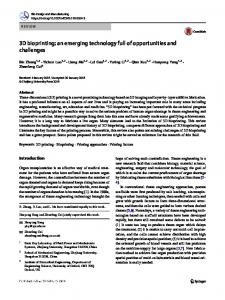
and Scheme S1 in the ESM). After that, SiO2@GF nanocomposites were reduced to Si@GF nanocomposites by the magnesiothermic reduction method [55]. Commercial Si powders, relevant intermediate products and hierarchical 3D mesoporous C@Si@graphene nanocomposites were characterized by X-ray diffraction (Fig. S4, ESM). In the third step, Si@graphene nanocomposites were coated with carbon nanolayers to afford hierarchical 3D mesoporous C@Si@graphene nanocomposites. Representative field emission scanning electron microscope (FESEM) and TEM images of C@Si@GF nanocomposites are presented in Fig. 1. As shown in Fig. 1(a), spherical Si nanoparticles (approximately 300 nm in size) are homogeneously distributed on the surface of graphene sheets. The inset in Fig. 1(a) further illustrates Si nanoparticles anchored on both sides of graphene sheets. Figure 1(b) shows a low magnification TEM image of C@Si@GF nanocomposites, from which the porous nature of the Si nanoparticles can be easily identified. A high magnification TEM image is shown in Fig. 1(c), which shows that the material consists of small Si nanocrystals with sizes of about 15 nm. The nanopores originate from the volume shrinkage during the conversion of SiO2 to Si, which has been confirmed by the dramatic increase of surface areas from 59.8 m2·g–1 (SiO2@GF) to 243.2 m2·g–1 (C@Si@GF) (Fig. S5 in the ESM). The pore size distribution of
Figure 1 FESEM and TEM characterisation of C@Si@GF nanocomposites prepared by CVD deposition for 5 h (the sample V). (a) FESEM image of C@Si@GF (Insert: Si spheres anchored on the two sides of graphene). (b) TEM image of Si spheres with mesoporous structure. (c) Si particles with approximate size of 15 nm wrapped by carbon layers and anchored on graphene sheets. (d) HRTEM image and SAED pattern demonstrating Si nanoparticles are covered by thin carbon layers.
SiO2@GF, obtained from the Barrett–Joyner–Halenda (BJH) method, is shown as the inset in Fig. S5(a), and exhibits a mean pore size of 4.5 nm. In contrast, the mean pore size increases to 9.87 nm for C@Si@GF
| www.editorialmanager.com/nare/default.asp
89
Nano Res. 2014, 7(1): 85–94
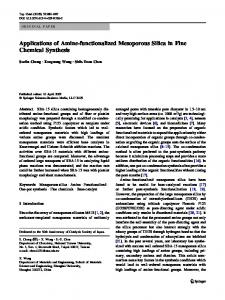
nanocomposites (inset in Fig. S5(b)). The mesoporous structures provide extra voids for Si nanospheres to expand during lithiation, and increase the specific area of C@Si@GF nanocomposites. The lattice resolved high-resolution transmission electron microscopy (HRTEM) image of Si nanocrystals is shown in Fig. 1(d). The interplanar distance of the lattice is measured to be 0.313 nm, corresponding to the (111) crystal planes of Si. It should be noted that thin carbon layers have been coated on Si nanocrystals with a thickness of about 1–2 nm, which can be expected to cushion the expansion of Si nanospheres during lithiation/de-lithiation and confine the maximum expansion volume. The diffraction rings in the SAED (insert in Fig. 1(d)) can be fully indexed to Si and graphene, which is consistent with the X-ray diffraction (XRD) patterns. Moreover, carbon layers coated on Si nanospheres can enhance the electrical conductivity of Si spheres. Tarascon and coworkers [56] have previously reported that compressive stress is induced by a carbon coating effect and demonstrated that the carbon layer derived from poly(vinyl chloride) and compressive pressure allows electrode particles to remain in good electrical contact during cycling, and thus limit the pulverization of the electrode. As shown in Fig. 2(b), commercial Si powder shows a Raman peak at 515 cm–1. However, C@Si@GF nanocomposites show a lower intensity and blue-shifted band at 505 cm–1, which might arise from the transverse optical mode. A similar phenomenon was previously reported [37] and ascribed to a phonon confinement effect, indicating the small size of the Si core and the thin nature of the carbon layers on the Si nanospheres. To confirm the presence of graphene and mesoporous Si nanospheres, energy-dispersive X-ray spectroscopy (EDS) mapping was performed over a random area of C@Si@GF nanocomposites (Fig. S6(a) in the ESM). Graphene layers in green (Fig. S6(b), ESM) and mesoporous Si nanospheres in red (Fig. S6(c), ESM) were detected, validating our structural design and demonstrating that mesoporous Si nanospheres were distributed on graphene sheets, with obvious voids appearing in the Si nanospheres. The content of Si in nanocomposites was determined to be 56 wt.% for the sample obtained by CVD deposition for 5 h
Figure 2 (a) Raman spectra of GF, Si, and C@Si@GF. (b) Magnified view of peaks marked in the image (a), demonstrating the blue shift of C@Si@GF band (I = Intensity).
(thermogravimetric analysis, TGA, Fig. S7(a), ESM). The relationships between load ratio, growth time and morphology were analyzed by thermogravimetric analysis (Fig. S7(b), ESM) and FESEM observations (Fig. S8, ESM). The electrochemical properties of the as-prepared mesoporous C@Si@GF nanocomposites were evaluated by cyclic voltammetry (CV) and galvanostatic charge/ discharge testing. Figures S9(a) and S9(b) in the ESM show the CV curves of bare Si and C@Si@GF electrodes, respectively. In Fig. S9(a), the irreversible cathodic peak at 0.75 V is associated with the formation of the solid electrolyte interphase (SEI) layer, and two anodic peaks at 0.31 V and 0.45 V correspond to the de-lithiation of Li+ from LixSi, which is similar to a previous report [20]. The C@Si@GF electrode only
www.theNanoResearch.com∣www.Springer.com/journal/12274 | Nano
Research
90
Nano Res. 2014, 7(1): 85–94
displays one anodic peak at 0.448 V. As indicated by Kovalenko et al. [20], the anodic peak at 0.3 V is related to the surface property of bare Si, which vanishes when Si particles are combined with carbon. This is also indirectly verified that Si nanospheres are coated with carbon layers in C@Si@GF nanocomposites. Figure 3(a) shows the charge/discharge profiles of bare Si and C@Si@GF nanocomposite electrodes at a current density of 100 mA/g in the first cycle. The C@Si@GF nanocomposite electrode delivered a reversible initial capacity of 1,480 mAh/g with a Coulombic efficiency of 66% in the first cycle (based on the content and theoretical capacity of carbon, a maximum capacity of 163.68 mAh/g may be contributed by the carbon). The bare Si electrode showed a reversible capacity of 1,610 mAh/g with a much lower Coulombic efficiency of 48% in the initial cycle. The
Figure 3 Electrochemical performance of the C@Si@GF composite electrode (sample V): (a) and (b) Galvanostatic charge– discharge profiles and cycling performances of Si and C@Si@GF nanocomposites with cut-off voltage between 5 mV and 2 V (C = specific capacity, N = cycle number).
irreversible capacity can be ascribed to the formation of the SEI layer on the surface of the electrode. From the second cycle, the C@Si@GF electrode exhibited a stable cycling performance with capacity retention of 89.1% after 200 cycles (Fig. 3(b)). In contrast, the specific capacity of the bare Si electrode quickly decreased to 25.8 mAh/g at the 20th cycle, exhibiting a very poor cyclability with a capacity retention of 1.6% after 200 cycles, which is related to the large volume expansion of Si electrodes during lithiation and repeated growth of SEI layers on Si electrodes by exposure to fresh electrolytes, resulting in pulverization of the Si electrodes. As shown in Fig. S8 (in the ESM), the size and weight percentage of Si nanoparticles in the C@Si@GF nanocomposites increased with extending the CVD deposition time. We also tested the electrochemical performances of C@Si@GF nanocomposites obtained after different deposition times (1, 2, 3, and 4 h). All the C@Si@GF electrodes exhibited excellent cycling performances (Fig. S10, in the ESM). The as-synthesized C@Si@GF electrodes were further tested at various step-wise current densities. The cells were subjected to charge/discharge cycling from 100 mA/g to 10 A/g and then reversed twice to 100 mA/g (Fig. 4(a)). The C@Si@GF electrode was quite tolerant to high rate cycling. When the current densities were reversed to lower values, the electrode recovered high capacities, which indicated that the integrity of the electrode was maintained. In order to test the long-term cycling performance at high current densities, the C@Si@GF electrodes (Fig. 4(b)) were cycled at 500 mA/g, 1 A/g, 5 A/g, and 10 A/g for 200 cycles. Mesoporous C@Si@GF nanocomposites demonstrated superior performance on long term cycling. The electrodes delivered specific capacities of 1,104 mAh/g and 969 mAh/g at 500 mA/g and 1 A/g after 200 cycles, respectively. Even at a current rate of 10 A/g, the electrode still achieved a capacity of 659 mAh/g after 200 cycles, illustrating the high power density of mesoporous C@Si@GF nanocomposites. This outstanding electrochemical performance can be ascribed to the unique nanoarchitecture. As observed by FESEM and TEM analyses, the nanocomposites consist of a hierarchical structure. Mesoporous Si nanospheres are coated with carbon layers and embedded in porous graphene foam networks, which provides
| www.editorialmanager.com/nare/default.asp
91
Nano Res. 2014, 7(1): 85–94
Figure 4 (a) Step-wise rate performance of C@Si@GF composites (sample V) at different current densities. (b) Cycling performances at high current densities.
Figure 5 (a) The a.c. impedance spectra of commercial silicon and C@Si@GF electrodes. Each cell was tested before and after cycling. (b) The corresponding equivalent circuit (RΩ: Ohm resistance; Rct: Charge transfer resistance; Zw: Warburg diffusion process; CPE: Constant-phase element).
sufficient space to cushion the volume change of Si during lithiation and de-lithiation processes. Moreover, Si nanospheres were also coated with a nanolayer of carbon, which enhances electronic conductivity for semi-insulating Si nanoparticles. The hierarchical nanostructures not only contribute to the high lithium storage capacity, but can also result in excellent high rate performance and long cycle life. The Si@GF nanocomposite without any carbon coating (Figs. S11(a) and S11(b)) presents a stable cycling performance only in the first 102 cycles and then quickly decreases to a relatively low capacity (560 mAh/g). This verified that the coated carbon layers play an important role in confining large volume expansion and maintaining good electrical contact with the electrode leading to the observed enhancement of cycling performance. The electrochemical impedance spectra of commercial Si and C@Si@GF electrodes in Fig. 5 further demonstrate the inner electrochemical resistances and interfacial properties (both before and after 200 cycles). The
corresponding equivalent circuit is presented in Fig. 5(b). All cells display Nyquist plots (Fig. 5(a)), which consist of a depressed semicircle at high frequency region and a straight line in the low frequency domain. The relatively small radius of the semicircle for C@Si@GF nanocomposites represents a lower electrochemical reaction resistance in the electrode, indicating it has higher electric conductivity than the bare Si electrode. Even when cycled for 200 times, the electrochemical resistance of C@Si@GF electrode was still much lower than that of the bare Si electrode. Post-mortem analyses were performed on the bare Si and mesoporous C@Si@GF electrodes after 200 cycles. Compared with original morphologies of the commercial Si particles (Fig. S12 in the ESM), Fig. 6(a) reveals that many cracks were formed on the surface of the bare Si electrode, which are presumably the major reason for the poor cyclability. In contrast, the C@Si@GF nanocomposite electrode retained a wellconnected nanostructure and integrity, with Si nanoparticles uniformly distributed on porous graphene
www.theNanoResearch.com∣www.Springer.com/journal/12274 | Nano
Research
92
Nano Res. 2014, 7(1): 85–94
nanocomposites exhibited superior electrochemical performance to that of pure silicon, including a high lithium storage capacity of 1,200 mAh/g at a current density of 1 A/g, excellent tolerance to high current densities and an outstanding cyclability. The approach developed here could also be extended to the synthesis of other 3D materials.
Acknowledgements This project is financially supported by the Australian Research Council (ARC) through the ARC Discovery project (No. DP1093855), ARC Future Fellowship project (No. FT110100800) and partially supported by the Chinese Scholarship Council (CSC, No. 2011689009). Figure 6 (a) and (b) SEM images of morphologies of (a) Si and (b) C@Si@GF electrodes after 200 cycles (insert images present greater detail). HRTEM images of (c) bare Si and (b) C@Si@GF electrodes after 200 cycles (the inserts in (c) and (d) show the SAED pattern of Si and the FFT pattern of C@Si@GF, respectively).
networks without any cracks even after long-term cycling (Fig. 6(b)). The HRTEM image and fast Fourier transform (FFT) pattern further confirmed the crystalline nature of Si nanoparticles after cycling (the insets in Figs. 6(c) and 6(d)). Therefore, the ex situ FESEM and TEM observations clearly verified that the mesoporous hierarchical nanoarchitecture can efficiently maintain the structural integrity of the electrode and significantly reduce the capacity fading on charge/discharge cycling.
4 Conclusion Mesoporous C@Si@GF nanoarchitectures have been successfully synthesized by a thermal bubble ejection assisted chemical-vapor-deposition and magnesiothermic reduction method. Mesoporous Si nanospheres were coated with a nanolayer carbon and embedded in graphene foam, which provides sufficient voids to cushion the large volume changes of Si during lithiation and de-lithiation processes and enhances the electronic conductivity of the semi-insulating Si nanoparticles. When employed as anode materials for lithium storage in lithium ion batteries, C@Si@GF
Electronic Supplementary Material: Supplementary material (digital photos of intermediate products of C@Si@GF nanocomposites, AFM imaging of graphene foam and C@Si@GF nanocomposites, Brunauer– Emmett–Teller (BET) results of SiO2@GF and C@Si@GF architectures, Raman spectra, XRD patterns of different products, TGA measurements of products obtained at different duration times, cyclic voltammograms and scanning electron microscopy (SEM) images) is available in the online version of this article at http://dx.doi.org/10.1007/s12274-013-0374-y.
References [1] Tang, W.; Hou, Y.; Wang, F.; Liu, L.; Wu, Y.; Zhu, K. LiMn2O4 nanotube as cathode material of second-level charge capability for aqueous rechargeable batteries. Nano Lett. 2013, 13, 2036–2040. [2] Wu, H.; Chan, G.; Choi, J. W.; Ryu, I.; Yao, Y.; McDowell, M. T.; Lee, S. W.; Jackson, A.; Yang, Y.; Hu, L., et al. Stable cycling of double-walled silicon nanotube battery anodes through solid-electrolyte interphase control. Nat. Nanotechnol. 2012, 7, 310–315. [3] Qu, Q.; Fu, L.; Zhan, X.; Samuelis, D.; Maier, J.; Li, L.; Tian, S.; Li, Z.; Wu, Y. Porous LiMn2O4 as cathode material with high power and excellent cycling for aqueous rechargeable lithium batteries. Energy Environ. Sci. 2011, 4, 3985–3990. [4] Yao, Y.; McDowell, M. T.; Ryu, I.; Wu, H.; Liu, N.; Hu, L.; Nix, W. D.; Cui, Y. Interconnected silicon hollow nanospheres for lithium-ion battery anodes with long cycle life. Nano Lett. 2011, 11, 2949–2954.
| www.editorialmanager.com/nare/default.asp
93
Nano Res. 2014, 7(1): 85–94
[5] Luo, J.; Zhao, X.; Wu, J.; Jang, H. D.; Kung, H. H.; Huang, J. Crumpled graphene-encapsulated Si nanoparticles for lithium ion battery anodes. J. Phys. Chem. Lett. 2012, 3, 1824–1829. [6] Wu, H.; Yu, G.; Pan, L.; Liu, N.; McDowell, M. T.; Bao, Z.; Cui, Y. Stable Li-ion battery anodes by in-situ polymerization of conducting hydrogel to conformally coat silicon nanoparticles. Nat. Commun. 2013, 4. 1493. [7] Etacheri, V.; Marom, R.; Elazari, R.; Salitra, G.; Aurbach, D. Challenges in the development of advanced Li-ion batteries: A review. Energy Environ. Sci. 2011, 4, 3243–3262. [8] Wu, Z. S.; Zhou, G.; Yin, L. C.; Ren, W.; Li, F.; Cheng, H. M. Graphene/metal oxide composite electrode materials for energy storage. Nano Energy 2012, 1, 107–131. [9] Wang, G.; Wang, B.; Wang, X.; Park, J.; Dou, S.; Ahn, H.; Kim, K. Sn/graphene nanocomposite with 3D architecture for enhanced reversible lithium storage in lithium ion batteries. J. Mater. Chem. 2009, 19, 8378–8384. [10] Chen, S.; Bao, P.; Xiao, L.; Wang, G. Large-scale and low cost synthesis of graphene as high capacity anode materials for lithium-ion batteries. Carbon 2013, 64, 158–169. [11] Wu, H.; Cui, Y. Designing nanostructured Si anodes for high energy lithium ion batteries. Nano Today 2012, 7, 414–429. [12] Kim, H.; Han, B.; Choo, J.; Cho, J. Three-dimensional porous silicon particles for use in high-performance lithium secondary batteries. Angew. Chem. Int. Ed. 2008, 47, 10151– 10154. [13] Ge, M.; Rong, J.; Fang, X.; Zhang, A.; Lu, Y.; Zhou, C. Scalable preparation of porous silicon nanoparticles and their application for lithium-ion battery anodes. Nano Res. 2013, 6, 174–181. [14] Liu, N.; Yao, Y.; Cha, J.; McDowell, M.; Han, Y.; Cui, Y. Functionalization of silicon nanowire surfaces with metalorganic frameworks. Nano Res. 2012, 5, 109–116. [15] Zhu, X.; Chen, H.; Wang, Y.; Xia, L.; Tan, Q.; Li, H.; Zhong, Z.; Su, F.; Zhao, X. S. Growth of silicon/carbon microrods on graphite microspheres as improved anodes for lithium-ion batteries. J. Mater. Chem. A 2013, 1, 4483–4489. [16] Kong, J.; Yee, W. A.; Wei, Y.; Yang, L.; Ang, J. M.; Phua, S. L.; Wong, S. Y.; Zhou, R.; Dong, Y.; Li, X., et al. Silicon nanoparticles encapsulated in hollow graphitized carbon nanofibers for lithium ion battery anodes. Nanoscale 2013, 5, 2967–2973. [17] Liu, N.; Wu, H.; McDowell, M. T.; Yao, Y.; Wang, C.; Cui, Y. A yolk-shell design for stabilized and scalable Li-ion battery alloy anodes. Nano Lett. 2012, 12, 3315–3321. [18] Kim, H.; Seo, M.; Park, M. H.; Cho, J. A critical size of silicon nano-anodes for lithium rechargeable batteries. Angew. Chem. Int. Ed. 2010, 49, 2146–2149. [19] Zhou, X.; Cao, A. M.; Wan, L. J.; Guo, Y. G. Spin-coated silicon nanoparticle/graphene electrode as a binder-free anode
[20]
[21]
[22]
[23]
[24]
[25]
[26]
[27]
[28]
[29]
[30]
[31]
for high-performance lithium-ion batteries. Nano Res. 2012, 5, 845–853. Kovalenko, I.; Zdyrko, B.; Magasinski, A.; Hertzberg, B.; Milicev, Z.; Burtovyy, R.; Luzinov, I.; Yushin, G. A major constituent of brown algae for use in high-capacity Li-ion batteries. Science 2011, 334, 75–79. Koo, B.; Kim, H.; Cho, Y.; Lee, K. T.; Choi, N. S.; Cho, J. A highly cross-linked polymeric binder for high-performance silicon negative electrodes in lithium ion batteries. Angew. Chem. Int. Ed. 2012, 51, 8762–8767. Magasinski, A.; Zdyrko, B.; Kovalenko, I.; Hertzberg, B.; Burtovyy, R.; Huebner, C. F.; Fuller, T. F.; Luzinov, I.; Yushin, G. Toward efficient binders for Li-ion battery Si-based anodes: Polyacrylic acid. ACS Appl. Mater. Interfaces 2010, 2, 3004–3010. Guy, D.; Lestriez, B.; Guyomard, D. New composite electrode architecture and improved battery performance from the smart use of polymers and their properties. Adv. Mater. 2004, 16, 553–557. Guo, J.; Wang, C. A polymer scaffold binder structure for high capacity silicon anode of lithium-ion battery. Chem. Commun. 2010, 46, 1428–1430. Kim, J. W.; Ryu, J. H.; Lee, K. T.; Oh, S. M. Improvement of silicon powder negative electrodes by copper electroless deposition for lithium secondary batteries. J. Power Sources 2005, 147, 227–233. Chen, D.; Mei, X.; Ji, G.; Lu, M.; Xie, J.; Lu, J.; Lee, J. Y. Reversible lithium-ion storage in silver-treated nanoscale hollow porous silicon particles. Angew. Chem. Int. Ed. 2012, 51, 2409–2413. Yu, Y.; Gu, L.; Zhu, C.; Tsukimoto, S.; van Aken, P. A.; Maier, J. Reversible storage of lithium in silver-coated threedimensional macroporous silicon. Adv. Mater. 2010, 22, 2247–2250. Yang, Z.; Guo, J.; Xu, S.; Yu, Y.; Abruña, H. D.; Archer, L. A. Interdispersed silicon–carbon nanocomposites and their application as anode materials for lithium-ion batteries. Electrochem. Commun. 2013, 28, 40–43. Cui, L. F.; Hu, L.; Choi, J. W.; Cui, Y. Light-weight freestanding carbon nanotube-silicon films for anodes of lithium ion batteries. ACS Nano 2010, 4, 3671–3678. Chen, P. C.; Xu, J.; Chen, H.; Zhou, C. Hybrid siliconcarbon nanostructured composites as superior anodes for lithium ion batteries. Nano Res. 2011, 4, 290–296. Deng, J.; Ji, H.; Yan, C.; Zhang, J.; Si, W.; Baunack, S.; Oswald, S.; Mei, Y.; Schmidt, O. G. Naturally rolled-up C/Si/C trilayer nanomembranes as stable anodes for lithium-ion batteries with remarkable cycling performance. Angew. Chem. Int. Ed. 2013, 52, 2326–2330.
www.theNanoResearch.com∣www.Springer.com/journal/12274 | Nano
Research
94
Nano Res. 2014, 7(1): 85–94
[32] Rong, J.; Fang, X.; Ge, M.; Chen, H.; Xu, J.; Zhou, C. Coaxial Si/anodic titanium oxide/Si nanotube arrays for lithium-ion battery anodes. Nano Res. 2013, 6, 182–190. [33] Magasinski, A.; Dixon, P.; Hertzberg, B.; Kvit, A.; Ayala, J.; Yushin, G. High-performance lithium-ion anodes using a hierarchical bottom-up approach. Nat. Mater. 2010, 9, 353–358. [34] Park, M. S.; Wang, G. X.; Liu, H. K.; Dou, S. X. Electrochemical properties of Si thin film prepared by pulsed laser deposition for lithium ion micro-batteries. Electrochim. Acta 2006, 51, 5246–5249. [35] Xin, X.; Zhou, X.; Wang, F.; Yao, X.; Xu, X.; Zhu, Y.; Liu, Z. A. 3D porous architecture of Si/graphene nanocomposite as high-performance anode materials for Li-ion batteries. J. Mater. Chem. 2012, 22, 7724–7730. [36] Lee, J. K.; Smith, K. B.; Hayner, C. M.; Kung, H. H. Silicon nanoparticles-graphene paper composites for Li ion battery anodes. Chem. Commun. 2010, 46, 2025–2027. [37] Hu, Y. S.; Demir-Cakan, R.; Titirici, M. M.; Müller, J. O.; Schlögl, R.; Antonietti, M.; Maier, J. Superior storage performance of a Si@SiOx/C nanocomposite as anode material for lithium-ion batteries. Angew. Chem. Int. Ed. 2008, 47, 1645–1649. [38] Huang, X.; Qian, K.; Yang, J.; Zhang, J.; Li, L.; Yu, C.; Zhao, D. Functional nanoporous graphene foams with controlled pore sizes. Adv. Mater. 2012, 24, 4419–4423. [39] Chen, S.; Chen, P.; Wu, M.; Pan, D.; Wang, Y. Graphene supported Sn–Sb@carbon core–shell particles as a superior anode for lithium ion batteries. Electrochem. Commun. 2010, 12, 1302–1306. [40] Ranjbartoreh, A. R.; Wang, B.; Shen, X.; Wang, G. Advanced mechanical properties of graphene paper. J. Appl. Phy. 2011, 109, 014306. [41] Hu, H.; Zhao, Z.; Wan, W.; Gogotsi, Y.; Qiu, J. Ultralight and highly compressible graphene aerogels. Adv. Mater. 2013, 25, 2219–2223. [42] Chen, Z.; Xu, C.; Ma, C.; Ren, W.; Cheng, H. M. Lightweight and flexible graphene foam composites for high-performance electromagnetic interference shielding. Adv. Mater. 2013, 25, 1296–1300. [43] Qiu, L.; Liu, J. Z.; Chang, S. L. Y.; Wu, Y.; Li, D. Biomimetic superelastic graphene-based cellular monoliths. Nat. Commun. 2012, 3, 1241. [44] Chen, Z.; Ren, W.; Gao, L.; Liu, B.; Pei, S.; Cheng, H. M. Three-dimensional flexible and conductive interconnected graphene networks grown by chemical vapour deposition.
Nat. Mater. 2011, 10, 424–428. [45] Zhao, Y.; Hu, C.; Hu, Y.; Cheng, H.; Shi, G.; Qu, L. A versatile, ultralight, nitrogen-doped graphene framework. Angew. Chem. Int. Ed. 2012, 51, 11371–11375. [46] Li, D.; Muller, M. B.; Gilje, S.; Kaner, R. B.; Wallace, G. G. Processable aqueous dispersions of graphene nanosheets. Nat. Nanotechnol. 2008, 3, 101–105. [47] Vickery, J. L.; Patil, A. J.; Mann, S. Fabrication of graphene–polymer nanocomposites with higher-order threedimensional architectures. Adv. Mater. 2009, 21, 2180–2184. [48] Xu, Y.; Sheng, K.; Li, C.; Shi, G. Self-assembled graphene hydrogel via a one-step hydrothermal process. ACS Nano 2010, 4, 4324–4330. [49] Kim, K. H.; Oh, Y.; Islam, M. F. Graphene coating makes carbon nanotube aerogels superelastic and resistant to fatigue. Nat. Nanotechnol. 2012, 7, 562–566. [50] Liang, H. W.; Guan, Q. F.; Chen, L. F.; Zhu, Z.; Zhang, W. J.; Yu, S. H. Macroscopic-scale template synthesis of robust carbonaceous nanofiber hydrogels and aerogels and their applications. Angew. Chem. Int. Ed. 2012, 51, 5101–5105. [51] Mecklenburg, M.; Schuchardt, A.; Mishra, Y. K.; Kaps, S.; Adelung, R.; Lotnyk, A.; Kienle, L.; Schulte, K. Aerographite: Ultra lightweight, flexible nanowall, carbon microtube material with outstanding mechanical performance. Adv. Mater. 2012, 24, 3437–3437. [52] Zou, Y.; Wang, Y. Sn@CNT nanostructures rooted in graphene with high and fast Li-storage capacities. ACS Nano 2011, 5, 8108–8114. [53] Chen, S. Q.; Wang, Y. Microwave-assisted synthesis of a Co3O4–graphene sheet-on-sheet nanocomposite as a superior anode material for Li-ion batteries. J. Mater. Chem. 2010, 20, 9735–9739. [54] Chen, S.; Bao, P.; Wang, G. Synthesis of Fe2O3–CNT– graphene hybrid materials with an open three-dimensional nanostructure for high capacity lithium storage. Nano Energy 2013, 2, 425–434. [55] Bao, Z.; Weatherspoon, M. R.; Shian, S.; Cai, Y.; Graham, P. D.; Allan, S. M.; Ahmad, G.; Dickerson, M. B.; Church, B. C.; Kang, Z., et al. Chemical reduction of three-dimensional silica micro-assemblies into microporous silicon replicas. Nature 2007, 446, 172–175. [56] Saint, J.; Morcrette, M.; Larcher, D.; Laffont, L.; Beattie, S.; Pérès, J. P.; Talaga, D.; Couzi, M.; Tarascon, J. M. Towards a fundamental understanding of the improved electrochemical performance of silicon–carbon composites. Adv. Funct. Mater. 2007, 17, 1765–1774.
| www.editorialmanager.com/nare/default.asp