Jan 5, 2004 - Programmers often rely on their source code to understand how their ..... Van Emden and Moonen (2002) describe a prototype code smell ...
Hierarchical Program Visualization David Fourney Cmpt. 816.3 (01) Project Submitted: January 5, 2004
Abstract Programmers often rely on their source code to understand how their software works. A visual representation of the software is one tool frequently used to help them understand the design, however they are often too large to use within a confined space. This paper describes a project that explores visual representations of a software system with particular attention on treemaps. Although, historically treemaps have been used in a variety of applications as a data visualization method, they have yet to be used to visualize software systems and metrics. The results of this project suggest that applications of treemaps to software visualization do exist and further exploration would be fruitful.
Introduction Accurate, complete, well-organized, and maintainable documentation is critical for software maintenance. Programmers often fall back on the source code to understand how their software works (Wong, 1993). Reverse engineering, the process of analyzing a system to identify its components and their interrelationships, and to create representations of it in another form or at a higher level of abstraction (Chikofsky & Cross, 1990), is one tool that programmers can use to understand their software. Representations of a software system can be made in either textual or graphical form. Representations in a textual form might include software metrics, module cross-reference listings, or reports of the interface between two modules (Wong, 1993). Textual representations, especially prose-like reports, have usability problems. For example, they can be very difficult to read for detail. However, textual representations easily allow further automated analyses. Consequently, visual representations are often used to visualize textual representations. Visual representations include function call graphs, inheritance hierarchies, control/data flow charts (Wong, 1993), or high-level overviews of the system such as conceptual (Soni, Nord, & Hofmeister, 1995), or concrete software architectures (Bowman, Holt, & Brewster, 1999). Visual representations of software systems can make program comprehension less taxing on the cognitive capacities of programmers since they quickly capture salient details of the system. However, they have several problems. For example, a visual representation can be too large to easily present (especially in limited space such as a computer monitor) requiring the viewer to either focus on one area of the representation or on a “bird’s eye” view of the representation as a whole, but handicapping the viewer by not allowing some other perspective of the visualization.
Hierarchical Program Visualization
2
Visual representations require a syntactically consistent notation to express their content, placing the burden on the reader to be familiar with the notation scheme. Normally, to ensure readers are familiar with the notation scheme, standardized notation systems (e.g., UML) are used, but these notation systems are often limited1 or inconsistent2. Finally, visual representations are also harder to use when performing further automated analyses. The goal of this project was to gather information about an object-oriented software system such as some metrics, the contents of each package, and the interrelationships among the packages (e.g., package hierarchy). In the case of the last two goals, it is desirable to generate some visual representation.
Background The first project goal, to collect metrics about the system, is fairly easy to solve as there are many tools (e.g., Unix’s wc) that can generate some software metrics. But the second and third goals, to visualize package contents and interrelationships, are usually much harder to do, especially with a single tool. Given the desire to visualize package relationships and contents, it seems obvious that the second and third goals can be best approached by the use of trees.
Trees Figure 1 shows a tree of UML packages. The tree has at least a dozen packages however they cannot all be seen. This style of tree takes up a lot of space since most of the pixels are used as background. As the tree grows, the space used expands quickly. There exists a clear need to view this same information more efficiently. For most users, their typical experience with tree representations is file systems. For example, the semi-graphic tree used in Windows Explorer displays the items of an active node in a parallel window, thus users only see information one folder at a time (see Figure 2).
Figure 1: A tree of packages.
Compared to the example of Figure 1, the semi-graphic tree format allows users to see many more nodes of the tree at once. However, this format has several issues. Large tree hierarchies require scrolling so users cannot begin to visualize the full tree at once making it harder to interpret. Since information can only be viewed one folder at a time, semi-graphic trees usually do not allow comparing the contents of one folder to another within the same window. Finally, as in the case of Windows Explorer, the point of the 1
For example, UML does not support real-time systems modeling (Lavazza, Quaroni, & Venturelli, 2001). For example, UML is composed of a set of notations that partially overlap. A subset of the state diagram notation can be used to express the same information that could be expressed in terms of pre/post conditions on operations in a class diagram (D’Souza & Wills, 1998). 2
Hierarchical Program Visualization
3
tree is to show the file folder hierarchy, not file and folder information, so any useful information (e.g., folder or file size, last modified date, etc.) cannot be seen at a glance.
Figure 2: Windows Explorer uses a semi-graphic tree.
Since existing trees seem too large or uninformative, the desire to visualize package relationships and contents might be better approached through reverse documenting applications that graphically display package information.
Reverse Documenting Applications Many applications available to programmers can show what classes are in a specific package, however it is rare to find tools that describe relationships among packages or describe the contents of multiple packages at once. Two of the tools explored for this project were BlueJ and ESS-MODEL. Although BlueJ (Kölling, Quig, Patterson, & Rosenberg, 2003) is an integrated development environment (IDE) specifically developed for teaching and learning objectoriented programming, it contains a highly functional visualization tool: a UML-based class structure display. The class structure display in its main window is designed to help students recognize and think about object-oriented design in Java. It shows the “uses” and “inheritance” relationships among classes within a package as well as the packages contained within a package. However, with the exception of containment (i.e., who contains what, who is contained within what), BlueJ does not show relationships among packages and, since there is no tree-based representation, BlueJ presents a “flat” view of any contained packages requiring the user to traverse several levels to see what other packages might exist. ESS-MODEL (n.d.) is a fast, easy to use UML-based reverse documenting tool. Like BlueJ, it generates class diagrams of Java source files and shows inheritance and associations. Unlike BlueJ, ESS-MODEL provides a semi-graphic tree to visualize package hierarchies and does not include packages within class diagrams. ESS-MODEL can also be used to show a class diagram of all classes in a software system regardless of package containment.
Hierarchical Program Visualization
4
The ability to view all the classes at once without package boundaries allows a programmer to ignore packages in favor of understanding how classes interrelate. Unfortunately, for a moderately sized application, the resulting diagram is rather large and can be difficult to view. Consequently, while ESS-MODEL met the goal of the project to both visualize the contents of each package and the package hierarchy (the semi-graphic tree), it presents several problems: it does not allow viewing the interrelationships among the packages in summary form, and it creates graphics that are too large to easily view. This tool exemplifies one problem of visual representations: they are often too large to easily present. Although the output of these reverse documenting tools is more informative than the hierarchical and semi-graphic trees typically used in software engineering, the problem of having a large amount of data being visualized over a small space persists. This is a problem that has been explored outside of the software engineering domain. One solution to this problem is the treemap.
Treemaps Treemaps were developed as an alternative to visual representations that are too large to easily present, especially in a limited space. A treemap is a hierarchy-viewing object that displays up to millions of elements at once showing multiple attributes. By recursively partitioning an element’s rectangle among its children, treemaps present the “ big picture” of a hierarchy giving users “ X-ray vision” into their heaps of data. In 1990, Ben Shneiderman needed to determine why his lab’s 80 Megabyte hard disk kept getting full. Since the hard disk was shared by fourteen users, it was difficult to determine how and where space was used. At the time, finding large files that could be deleted, or even determining which users consumed the largest shares of disk space were difficult tasks. File system trees, like the one displayed in Windows Explorer, simply got too large to be useful (Shneiderman, 1998). Shneiderman explored ways to show a tree in a space-constrained layout rejecting strategies that left blank spaces or dealt with only fixed levels or fixed branching factors. Although showing file size by area coding seemed appealing, various rectangular, triangular, and circular strategies all had problems. Finally he arrived at the notion of splitting the screen into rectangles in alternating horizontal and vertical directions while traversing down the levels (Shneiderman, 1992). The term “ Treemap” describes Shneiderman’s idea of turning a tree into a planar spacefilling map. Treemaps are useful because they efficiently use available screen space, are easy to comprehend, and can be esthetically pleasing (Shneiderman, 1998). Treemaps are also quite easy to read and several good tutorials on reading treemaps are available (e.g., http://www.win.tue.nl/sequoiaview/Main_Frame/Treemaps.html). Since Shneiderman’s original implementation based on thin rectangles, several varieties of treemaps have been developed. For example, “ cushion treemaps” show depth of nesting by shadows on cushion-like 3-D mounds (van Wijk & van de Wetering, 1999),
Hierarchical Program Visualization
5
“ squarified treemaps” avoid high aspect ratio rectangles (Bruls, Huizing, & van Wijk, 2000), and “ cluster treemaps” ensure low aspect ratio rectangles (Wattenberg, 1999). These innovations attempt to resolve some of the limitations of treemaps such as difficulties when visualizing tree structure. For example, in a balanced tree, where each parent has the same number of children and each leaf has the same size, treemaps degenerate into a regular grid (van Wijk & van de Wetering, 1999). Thus, a treemap can solve the problem of visualizing a large amount of information in a limited space. Outside of viewing filesystems, treemaps have been applied to the Analytical Hierarchy Process in decision making (Asahi, Turo, & Shneiderman, 1995), a satellite management system (Kumar, Plaisant, Teittinen, & Shneiderman, 1994), and analysis of Usenet variation (Smith, & Fiore, 2001). Given treemaps have been used in a variety of applications as a visualization method for large amounts of data and tree-like visualization methods (e.g., package trees, semi-graphic trees) are often used to understand software, treemaps could be used to visualize software. Interestingly, no one has tried this yet.
Method The project has three main phases. In the first phase, a candidate software system is chosen. For the purposes of this project, for a candidate software system to be considered, it should be small enough for human comprehension of most of it yet large enough for considerable visualization. Candidates are also considered on the basis of programming language and adherence to object-oriented design. Software metrics (e.g., lines of code, number of files, number of packages, programming language, etc.) can be generated using a combination of the Unix tool find(1)3 and a Perl script that counts the number of lines, non-comment non-blank lines and statements in a file (Appleton, 1995) as well as the Unix tool wc. The goal of the second phase of the project is to develop program understanding. Tools such as BlueJ and ESS-MODEL are used to generate and explore a concrete architecture of the software system. Code-browsing tools, as well as the execution of the candidate software are other tools used in developing program understanding. Since treemaps have been used in a variety of applications as a visualization method, but not to visualize software, the third and final phase of the project is to explore the application of various treemap visualizations to the software system. Initial explorations include file structure, class size, and depth of tree.
Results and Discussion Phase 1 After exploring various libraries of Open-Source Software, Pooka was chosen as the software system to be investigated. Pooka is an email client written in Java using the 3
To be precise the command is: find . –type f –exec perl clc.perl {} \;
Hierarchical Program Visualization
6
Javamail and Swing APIs. It is released under the GNU General Public License. Pooka can be executed as either a stand-alone application or in a web browser through Java Web Start technology. Pooka can be found at Sourceforge (http://sf.net/projects/pooka/). Pooka supports email through the IMAP (connected and disconnected), IMAP over SSL, and POP3 protocols. Outgoing email is sent via SMTP. Support for standard email client features such as attachments, signatures, filters, address book and multiple email accounts is included. The graphical user interface includes both a Eudora-like desktop and an Outlook-like preview window. In summary, the source code metrics of Pooka are: • 270 files, including: o 218 Java (26 packages), 24 graphics, 19 text, 16 HTML, 2 XML • 53 685 total lines of code o mean 198 LOC, median 90 LOC, and the mode 7 LOC • 4 096 total bytes
Phase 2 Using both BlueJ and ESS-MODEL to explore the design of Pooka led to some realizations of the weaknesses and strengths of each tool. BlueJ output was eventually discarded since it does not show relationships among packages and presents a “ flat” view of any contained packages requiring the user to traverse several levels to see what other packages might exist.
Figure 3: UML Model of Pooka
The output of ESS-MODEL met the goal of the project to both visualize the contents of each package and the package hierarchy, but it did not allow viewing the interrelationships among the packages in summary form, and it created an overall architecture diagram that was twelve feet high by 26 feet across. Figure 3 shows a
Hierarchical Program Visualization
7
“ bird’ s eye” view of the resulting UML diagram. Note ESS-MODEL ignores package boundaries. Pooka’ s code was browsed using the ECB plug-in for Emacs (http://ecb.sf.net/) and the application itself was executed. This process allowed further understanding of the code. This exploration showed that one package, which provides LDAP support to the Address Book, is not used at all by the program.
Figure 4: A screenshot of Pooka in Desktop mode.
Figure 4 shows Pooka’ s Eudora-like desktop mode.
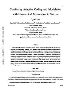
Phase 3 Pooka was applied to various treemap visualizations wit the assistance of treemap viewing tools. Two applications supporting treemap visualizations are: • Shneiderman’ s Treemap 4.0 (http://www.cs.umd.edu/hcil/treemap/), and • Fekete and Plaisant’ s (2002) millionvis(http://www.cs.umd.edu/hcil/VisuMillion/) These applications were chosen for use in this project because both have: • user-interactive features that allow real-time changes of the view, and • the ability to accept fact files about the software under investigation. Initially, a visualization of the file structure was explored. As seen in Figure 5, each file
Hierarchical Program Visualization
8
type was given a different color (i.e., red for Java, green for graphics, blue for HTML, cyan for XML, and white for text). To assist in viewing the tree structure, Treemap 4.0’ s support of nested treemaps was used. This view confirmed the ratios of files seen in Phase 1. It is clear that the majority of files are Java classes. The treemap suggests that the user may not see the two XML files. Note that this tool has an advantage over Windows Explorer in that further information about a file is available through tooltips.
Figure 5: Treemap of Pooka file distribution.
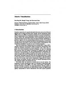
Using millionvis, a visualization of class size, in LOC, was explored. As seen in Figure 6, every Java class was colored yellow. Each square shows the size of the class (the bigger the square, the bigger the class). The thin border lines show the package boundaries. Color-coding on the basis of class type was not particularly useful as the display, essentially a wall of yellow squares, was too homogenous. This view results from the tool being configured to only analyze application-specific Java classes and ignore text, HTML, and XML files which had no impact on the application. To enhance portability, Java applications tend to be homogeneous (i.e., everything is covered by a Java class), consequently, this visualization would likely be more useful in applications that make use of code written in a variety of languages. For example, this visualization
Hierarchical Program Visualization
9
may be very useful for applications written in multiple programming languages and packaged using Microsoft’ s .Net technology.
Figure 6: Treemap of Pooka Java code.
Fowler (1999) introduced the metaphor of “ code smells” to describe indicators that refactoring may be beneficial. The visualization in Figure 6 may be useful in detecting specific code “ smells” such as classes that are too big. Although the file size visualization in Figure 5 dramatically suggests certain class files (e.g., FolderInfo.java) might need some attention due to their size, the class size visualization in Figure 6 does not. Since two different tools were used to implement these visualizations, this difference may be an artifact of the tool. A statistical analysis of the detailed source code metrics generated during Phase 1 shows that Pooka’ s classes average around 200 LOC. FolderInfo is in fact the largest class at 2447 LOC with MessageProxy at 1484 LOC being a distant second. Thus, the failure of the class size visualization in Figure 6 to highlight the smellier code in FolderInfo and MessageProxy is an artifact of the tool. A visualization of depth of tree was explored in two ways. First, the squares in Figure 6 are shaded such that the darker the square’ s shading the deeper it is in the tree. Second,
Hierarchical Program Visualization
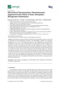
as shown in Figure 7, color was applied such that the darker the color, the higher the position in the tree. In this case, yellow is used to show one level of the hierarchy not Java classes. The thin border lines show the package boundaries. This visualization suggests that there are only three levels to the tree, which in fact can be confirmed by viewing the tree hierarchically. This visualization dramatically detects a potential code smell: too many or too few packages.
Figure 7: Treemap of Pooka class/package tree depth.
One potential use of this type of visualization is the depiction of a call graph where the tree depth would be interpreted as the depth or number of calls in a path. Another application would be the visualization of inheritance hierarchies where classes of a specific color are all related to each other. Together, these three visualizations, file size, class size and tree depth, show that color, size and aspect ratio can be combined to communicate interesting information about a software system at a glance.
10
Hierarchical Program Visualization
11
Conclusion The results of Phase 3 suggest that, unlike the UML diagram in Figure 3, treemaps can be used to visualize both package contents and interrelationships (e.g., package hierarchies) simultaneously. Moreso, it appears that treemaps may also highlight information about the code such as the need for refactoring (i.e., code smells). Van Emden and Moonen (2002) describe a prototype code smell browser, jCOSMO, which uses the Rigi Standard Format (RSF) to visualize extracted facts. Unfortunately, Rigi does not allow variations of color and size of a node to indicate the presence of a code smell forcing these researchers to add additional nodes as code smell markers. An interesting future endeavor would be the use treemap features such as its ability to vary color and size of a node as the visualization tool of jCOSMO to show the presence of smelly code. The results of Phase 3 also suggest the need for further investigation of metrics that can be analyzed with the help of treemaps. For example, investigation of Pooka’ s source code with a metrics analysis tool revealed that the FolderInfo class has a high cyclomatic complexity. Applications of McCabe’ s cyclomatic complexity metric in object-oriented code has not been extensive since one advantage of the object-oriented paradigm, replacing CASE statements with polymorphism and inheritance, drops the metric to its minimum (Henderson-Sellers, 1996). Thus, high cyclomatic complexity is in itself a code smell. Using a treemap, a programmer can, at a glance, visualize patterns of complexity and identify source code modules that require human investigation. In conclusion, although historically treemaps have been used in a variety of applications as a visualization method, they have not been used to visualize software. The results of this project suggest that applications of treemaps to software visualization do exist and further exploration would be fruitful.
References Appleton, B. (1995). http://www.chris-lott.org/resources/cmetrics/clc.tar.gz Asahi, T., Turo, D., & Shneiderman, B. (1995). Using Treemaps to Visualize the Analytic Hierarchy Process. Information Systems Research, 6(4), 357-375. ftp://ftp.cs.umd.edu/pub/hcil/Reports-Abstracts-Bibliography/3293html/3293.html Bowman, I., Holt, R., & Brewster, N. (1999). Linux as a case study: Its extracted software architecture. In Proceedings of the 21st International Conference on Software Engineering (ICSE), 555-563. Bruls, M., Huizing, K., & van Wijk, J. J. (2000). Squarified Treemaps. In Proceedings of Joint Eurographics and IEEE TCVG Symposium on Visualization (TCVG 2000), 3342. IEEE Press. http://www.win.tue.nl/~vanwijk/stm.pdf
Hierarchical Program Visualization
12
Chikofsky, E. & Cross, J. (1990). Reverse engineering and design recovery: A taxonomy. IEEE Software, 7(1), 13-17. D’Souza, D. & Wills, A. (1998). Objects, Components and Frameworks with UML: The Catalysis Approach. Addison-Wesley. ESS-MODEL (n.d.). http://essmodel.sourceforge.net/ Fekete, J.-D., & Plaisant, C. (2002). Interactive Information Visualization of a Million Items. In Proceedings of IEEE Symposium on Information Visualization 2002 (InfoVis 2002), 117-127. http://www.lri.fr/~fekete/ps/MillionVis.pdf Fowler, M. (1999). Refactoring: Improving the design of existing code. Addison-Wesley. Henderson-Sellers, B. (1996). Object-oriented metrics: Measures of complexity. Saddle River, NJ: Prentice Hall. Kölling, M., Quig, B., Patterson, A. and Rosenberg, J. (2003). The BlueJ system and its pedagogy. Journal of Computer Science Education, Special issue on Learning and Teaching Object Technology, 13(4), 249-268. http://www.bluej.org/papers/2003-12CSEd-bluej.pdf Kumar, H., Plaisant, C., Teittinen, M., & Shneiderman, B. (1994). Visual information management for network configuration (Technical Report HCIL-94-07, CS-TR-3288, CAR-TR-716, ISR-TR-94-45). ftp://ftp.cs.umd.edu/pub/hcil/Reports-AbstractsBibliography/94-07html/94-07.html Lavazza, L., Quaroni, G., & Venturelli, M. (2001). Combining UML and formal notations for modelling real-time systems. In Proceedings of the 8th European software engineering conference held jointly with 9th ACM SIGSOFT international symposium on Foundations of software engineering, 196-206. http://doi.acm.org/10.1145/503209.503236 Shneiderman, B. (1992). Tree visualization with tree-maps: 2-d space-filling approach. ACM Transactions on Graphics (TOG), 11(1), 92-99. http://doi.acm.org/10.1145/102377.115768 Shneiderman, B. (1998) Treemaps for space-constrained visualization of hierarchies. http://www.cs.umd.edu/hcil/treemap-history/index.shtml Smith, M. & Fiore, A. (2001). Visualization components for persistent conversations. In Proceedings of the SIGCHI conference on Human factors in computing systems, 136143. http://doi.acm.org/10.1145/365024.365073
Hierarchical Program Visualization
13
Soni, D., Nord, R. L., & Hofmeister, C. (1995). Software Architecture in Industrial Applications. In Proceedings of the 17th International Conference on Software Engineering (ICSE), 196-207. van Emden, E., & Moonen,L. (2002). Java quality assurance by detecting code smells. In Proceedings of the 9th Working Conference on Reverse Engineering (WCRE 2002), 97-108. http://homepages.cwi.nl/~leon/papers/wcre2002/wcre2002.pdf van Wijk, J. & van de Wetering, H. (1999). Cushion treemaps: Visualization of hierarchical information. In Proceedings of the 1999 IEEE Symposium on Information Visualization (INFOVIS), 73-78. http://www.win.tue.nl/~vanwijk/ctm.pdf Wattenberg, M. (1999). Visualizing the stock market. CHI ’99 extended abstracts on Human factors in computer systems, 188-189. http://doi.acm.org/10.1145/632716.632834 Wong, K. (1993). Managing views in a program understanding tool. In Proceedings of the 1993 IBM/NRC CAS Conference (CASCON ’93), 244-249. http://www.rigi.csc.uvic.ca/Pages/publications/mvput.pdf