Jan 12, 2012 - Page 1. High-Gain Magnetized Inertial Fusion. Stephen A. Slutz and Roger A. Vesey. Sandia National Laboratories, P. O. Box 5800, ...
PRL 108, 025003 (2012)
week ending 13 JANUARY 2012
PHYSICAL REVIEW LETTERS
High-Gain Magnetized Inertial Fusion Stephen A. Slutz and Roger A. Vesey Sandia National Laboratories, P. O. Box 5800, Albuquerque, New Mexico 87185-1186, USA (Received 3 June 2011; published 12 January 2012) Magnetized inertial fusion (MIF) could substantially ease the difficulty of reaching plasma conditions required for significant fusion yields, but it has been widely accepted that the gain is not sufficient for fusion energy. Numerical simulations are presented showing that high-gain MIF is possible in cylindrical liner implosions based on the MagLIF concept [S. A. Slutz et al Phys. Plasmas 17, 056303 (2010)] with the addition of a cryogenic layer of deuterium-tritium (DT). These simulations show that a burn wave propagates radially from the magnetized hot spot into the surrounding much denser cold DT given sufficient hot-spot areal density. For a drive current of 60 MA the simulated gain exceeds 100, which is more than adequate for fusion energy applications. The simulated gain exceeds 1000 for a drive current of 70 MA. DOI: 10.1103/PhysRevLett.108.025003
PACS numbers: 52.58.Lq
This Letter describes the first detailed numerical simulations of magnetized inertial fusion (MIF), which attain high gain ( > 100) and thus are of considerable interest for fusion energy. Here we define the gain, G, as the ratio of the fusion yield divided by total (kinetic þ internal) energy absorbed by the liner and the magnetized fuel during the implosion. The gain required for inertial fusion energy is given by the expression G�E fRP �D ¼ 1, where �E � 0:4 is the electrical generating efficiency, fRP � 0:25 is the fraction of the generated power that must be recirculated to run the plant and driver, and �D is the driver efficiency. As much as 20% of the wall plug energy can be delivered to a magnetically driven liner implosion, i.e., �D � 0:2. Despite the high efficiency of magnetic implosions, a gain of 50 is still required. This is why the possibility of high-gain MIF designs such as presented in this Letter is important. In inertial confinement fusion (ICF), fusion conditions are obtained by applying pressure to the outside of a capsule (spherical shell) or liner (cylindrical tube) causing an implosion, which compresses and heats deuteriumtritium (DT) fuel up to temperatures in excess of the ideal ignition temperature �4 keV (46 400 000 K). This implosion must be fast enough so that compressive heating is larger than all loss mechanisms, such as thermal conduction and radiation [1]. Typically implosion velocities exceeding 30 cm=� sec are required for ICF implosions [2]. It was recognized in 1949 that a magnetic field could significantly reduce electron thermal conductivity [3], and could consequently lower the required implosion velocity needed for inertial fusion. However, it was several years after the proposal of ICF [4] that MIF was proposed and experimentally demonstrated to improve ICF yields [5,6]. Lindemuth and Kirkpatrick [7] performed calculations indicating that gains greater than unity could be obtained for rather slow implosion velocities (< 1 cm=� sec) when a magnetic field provided magnetothermal insulation and the initial fuel densities were low 0031-9007=12=108(2)=025003(5)
(� 1 �g=cm3 ) to keep radiation losses down. In addition to reducing the thermal conductivity, a magnetic field inhibits the transport of � particles out of the burning fuel [8], thus � particle heating of the fuel can be important even for very low fuel areal densities. A number of researchers are presently exploring this low-density regime, often referred to as magnetized target fusion [9]. A variety of magnetic field configurations are possible [10], but the most developed concept uses a field-reversed configuration [11] with a plasma temperature of about 500 eV. Slutz et al. performed detailed numerical simulations [12], which indicated that magnetized and preheated fuel at higher densities (� 1 mg=cm3 ) could attain fusion conditions in gas filled liner implosions driven on a 100 ns time scale with implosion velocities less than 10 cm=� sec, higher than those for magnetized target fusion, but still much smaller than typical ICF capsule implosions. We shall refer to this regime as magnetized liner inertial fusion (MagLIF). Note that the fuel must be preheated for implosion velocities below about 20 cm=� sec to obtain the fusion ignition temperatures without very large convergence ratios [12]. This can be accomplished using a laser to heat the DT fuel prior to the implosion in the MagLIF scenario. Laserdriven magnetized fuel implosions at high implosion velocities have been proposed that would not require preheat [13,14]. Indeed, enhanced yield due to the magnetization of such capsules has been recently reported [15]. The primary attraction to any MIF scheme is that the power required to drive these slow velocity implosions is significantly smaller than required for standard ICF and could potentially offer a low cost approach to fusion [16]. Jones and Mead [17] performed detailed numerical simulations of spherical capsules, which supported the conclusion that a magnetic field could improve volume burn of a DT gas. However, they also showed that a magnetic field tended to inhibit the propagation of a burn wave into a surrounding layer of cold dense DT. Because of this result
025003-1
Ó 2012 American Physical Society
PRL 108, 025003 (2012)
PHYSICAL REVIEW LETTERS
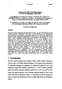
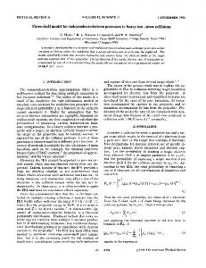
it has been widely accepted that MIF cannot produce gains more than about 10, which would not be adequate for fusion energy. High gain is obtained in inertial fusion capsules by designing implosions so that energy is invested in heating only a small portion of the fuel at the center above ignition temperature at stagnation, while the rest of the fuel surrounding this hot spot remains relatively cold and is consequently compressed to high density without a large expenditure of energy. The ignition of the hot spot triggers a burn wave that propagates outward through the dense fuel. This burn wave is a deflagration in the sense that heat conduction and �-particle transport are more important than shock heating. Since both �-particle transport and thermal conduction are reduced by a strong transverse BZ magnetic field, the burn wave will be inhibited; however, not precluded. A potential high-gain configuration for the MagLIF approach is depicted in Fig. 1. The primary modification to the standard MagLIF is the addition of a dense cryogenic layer of DT on the inside surface of the metal liner. For now we assume this layer is solid DT ice, but liquid DT options might be possible. The operation is essentially the same as for the standard MagLIF. Exterior field coils (not shown) provide an initial BZ of 10–30 T. A laser beam enters from above to preheat the central portion of the fuel before the liner implodes. The liner is imploded by the large azimuthal magnetic field, B� , induced by the drive current from a pulsed-power accelerator such as Z [18]. During the implosion a hot spot is formed from the preheated fuel, which is compressively heated above the ignition temperature with modest liner convergence ratios of 15–25, where the convergence ratio is defined as the ratio of the initial over final radius of the inner surface of the liner. We expect the cryogenic DT layer will be compressed to high density with minimal energy expenditure. According to previous MagLIF simulations [12], the initial axial magnetic field is compressed to strengths exceeding 10 000 T (100 MG). Note that recent experiments [14,19] have demonstrated flux compression of an initial field of 6.2 T up to a final field of 3600 T. This field inhibits both electron thermal conductivity and the transport of � particles, which is good
FIG. 1 (color).
Schematic of a high-gain MagLIF.
week ending 13 JANUARY 2012
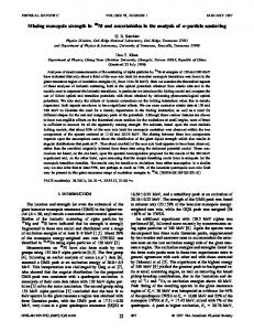
for obtaining ignition but could inhibit radial burn into the dense fuel layer formed from the cryogenic layer of DT upon stagnation. To determine the conditions necessary to obtain radial propagation of a burn wave from a magnetized hot spot into a surrounding layer of cold dense DT we performed a large number of simplified 1D simulations. These cylindrical simulations were started from an idealized compressed state similar to that which could be obtained by a liner implosion. A super-Gaussian temperature profile was used of the form TðtÞ ¼ T0 expð� �r Þn , where � defines the scale of the hot spot, n defines the steepness of the temperature gradient, and T0 was set to 10 keV, with the hot spot defined as the region with T > 4 keV. Since we do not expect large radial pressure variations at stagnation, we make the simplifying assumption that the pressure is not a function of radius at this initial time. The central gas density, which for this study is in the range 0:1–10 g=cm3 , then defines the pressure, which determines the density at each radius through the equation of state of either DT or the liner material which was aluminum for this study. A uniform axial magnetic field is imbedded within the entire model simulation and the evolution is followed using the radiation-magneto-hydrodynamics code LASNEX [20]. LASNEX is a well-validated inertial fusion code that can model the physics important to this problem. In particular, the effects of an axial magnetic field on electron thermal conduction and the transport of � particles in the radial direction are modeled. A diffusion model of the � particles is used where the diffusion coefficient has been adjusted to agree with the solution of Basko [8]. The ratio of the yield obtained from the initially cold fuel, Ycold , over the yield from the hot spot, Yhot , is a measure of how effectively the burn wave has propagated into the cold fuel. Large ratios are desired because much less energy is needed to compress the cold fuel than the hot spot. A contour plot of Ycold =Yhot as a function of hot-spot areal density and the ratio of the hot-spot radius over the �-particle cyclotron radius, R=R� / BR, is shown in Fig. 2 for simulations assuming a liner areal density of 5 g=cm2 and a central fuel density of 10 g=cm3 . A dotted white line is also plotted corresponding to a peak temperature of 15 keV indicating significant self-heating of the hot spot, i.e., hotspot ignition. The required hot-spot areal density decreases with increasing BR as expected due to the reduction of thermal and �-particle losses from the hot spot. However, too much field inhibits the transport of heat from the hot spot into the cold fuel layer; consequently, there is an optimum BR leading to the minimum hot spot areal density for propagation as exhibited by the contour Ycold =Yhot ¼ 2, which indicates an approximate threshold for propagation. Note that without a magnetic field, the hot-spot areal density required for ignition or propagation is about 0:11 g=cm2 . This is only reduced by about 30%–40% by introducing a magnetic field, which may have led Jones
025003-2
PRL 108, 025003 (2012)
PHYSICAL REVIEW LETTERS
FIG. 2 (color). Contours of the ratio Ycold =Yhot from simulations are plotted (color shading and black curves). Regions of Ycold =Yhot > 1 indicate propagating burn. The white dotted line corresponds to peak fuel temperature equal to 15 keV and indicates hot-spot ignition. This occurs at much lower hot-spot areal density than propagation. The areal density of the metal liner was 5:0 g=cm2 in these simulations.
and Mead to conclude that there is little advantage to magnetization. However, they overlook the important point that magnetization of the fuel makes it much easier to attain these conditions, by suppressing thermal conduction during the implosion. This simulation study indicates that the required hotspot areal density for propagating burn is very weakly dependent on the hot-spot density in the range, 0:1–10 g=cm3 . It is also relatively insensitive to the value of n in the initial super-Gaussian temperature profile over the range (2–8) because the temperature profile quickly relaxes to a more realistic profile during the numerical simulation. However, it does depend significantly on the areal density of the metal liner. This is because the liner areal density determines the inertial confinement time. A longer confinement time allows burn wave propagation with larger magnetic inhibition of the transport, thus allowing hot-spot ignition at lower areal densities, e.g., a hot-spot areal density of 0:03 g=cm2 is sufficient for propagation with a liner areal density of 10 g=cm2 . Standard MagLIF simulations [12] indicate hot-spot areal densities of about 0:07 g=cm2 and liner areal densities are about 5 g=cm2 for peak drive currents of 60 MA, which according to Fig. 2 could have produced a propagating burn wave if there had been a surrounding layer of dense fuel. Therefore we performed full implosion LASNEX simulations of MagLIF with an added layer of DT ice as depicted in Fig. 1. A circuit model of the existing Z accelerator is used, which produces current pulses rising to peak in about 100 ns. The circuit source voltage is varied to obtain peak currents ranging from 30–70 MA as an approximation to the output from future accelerators. Note that the existing Z accelerator can produce about 27 MA at maximum Marx charge voltage. The initial DT gas density (5–10 mg=cm3 ), ice layer thickness, magnetic field strength (10–30 T), laser pulse length (10–30 ns) and
week ending 13 JANUARY 2012
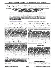
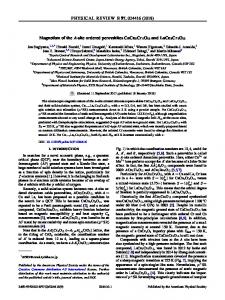
FIG. 3 (color). Simulated yields (solid curves) and gains (dashed curves) plotted as a function of peak drive current. The black curves are for standard MagLIF while the colored curves are the results for MagLIF simulations that include a cryogenic layer of DT ice on the inner surface of a liner (beryllium shown as red, aluminum as blue).
timing are optimized for each value of the peak current. These simulations indicate hot-spot densities of 5–10 g=cm3 , peak cold fuel densities of 100–250 g=cm3 , and radial burn wave propagation into the cold fuel producing large yields as shown in Fig. 3. The results for the high-gain MagLIF configuration with a DT ice layer are colored (beryllium shown as red, aluminum as blue), while the results for the standard MagLIF configuration without an ice layer are black. The yield curves are solid and the gain curves are dashed. The gain for the standard MagLIF is about 8 at a peak driving current of 60 MA, while the high-gain MagLIF has a gain exceeding 100. Note highgain MagLIF simulations exhibit better performance than the standard MagLIF for peak currents exceeding 30 MA and the improvement becomes very pronounced above 55 MA. The simulated gain of the high-gain MagLIF exceeds 1000 at a peak current of 70 MA. The required laser-preheat energy, ELAS , and the energy absorbed by the liner from the magnetic implosion, EABS , increase monotonically with peak drive current, while the optimum initial field, BZ , decreases. Over the range of peak currents from 30 to 70 MA, the optimum BZ decreases from 30 to 11 T, EABS ranges from 1.5 to 9:3 MJ=cm, and ELAS increases from 8 to 22 kJ. Assuming a magnetic drive efficiency of 20% and a laser efficiency of 10% (achievable with diode pumped lasers [21]) the laser bank energy is less than 1.1% of the bank energy driving the liner implosion. The decrease in the optimal BZ with peak current is consistent with the results of Fig. 2, since burn propagation is only important for the larger peak currents. We performed a study to determine the sensitivity of the high-gain MagLIF simulations to possible errors in transport modeling. Electron thermal conduction is a function of !e �e and the transport of the � particles is a function of !� �� , where !e and !� are the electron and � particle cyclotron frequencies and �e and �� are the electron and �-particle collision frequencies. In this study we multiply these two quantities by arbitrary multipliers Me and M� ,
025003-3
PRL 108, 025003 (2012)
PHYSICAL REVIEW LETTERS
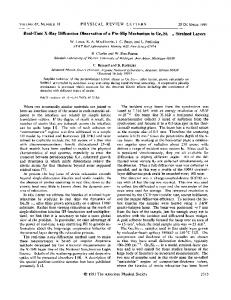
FIG. 4 (color). Contours of optimum initial magnetic field (black curves and colored background) and contours of constant yield (white curves) are plotted as a function of the logarithm of two arbitrary multipliers M� and Me described in the text.
respectively, and adjust the initial magnetic field to maximize the yield for a high-gain MagLIF design driven by a peak current of 70 MA with a nominal yield of 10:5 GJ=cm. Contours of the optimal initial axial magnetic field (black) and contours of constant yield (white) are plotted in Fig. 4. The results indicate that nominal yield can be obtained over a large space simply by adjusting the initial magnetic field. Note further that the yield and B-field contours become flat in the limit that M� goes to zero (to the left of the plot). This is because electron thermal conduction can support propagating burn without �-particle transport. This has been verified by running simulations with instantaneous �-particle deposition. Therefore the existence of high-gain configurations is not sensitive to transport modeling errors. As with all inertial fusion, the Rayleigh-Taylor (RT) instability can degrade the performance. We have used a liner aspect ratio R=�R ¼ 6 for all the 1D simulations presented here. Two-dimensional simulations [12] of the standard MagLIF indicated that this choice of aspect ratio should be robust to the RT instability. We have performed an additional series of 2D simulations to determine the sensitivity of the high-gain-MagLIF to surface roughness for a liner driven at 60 MA. The results are plotted in Fig. 5. These simulations were started with surface roughness on the inner and outer boundaries of aluminum liners. The rootmean-squared (RMS) amplitude was varied for each of the simulations, while keeping a flat spectrum of modes from the minimum wavelength resolved by the axial spacing of the mesh to the maximum wavelength corresponding to the length of the simulation. The simulations were performed with four different axial resolutions. The curves are labeled with the smallest wavelength that was resolved in �m. The results clearly indicate that the yield is more robust to the longer wavelength perturbations. Comparison of LASNEX simulations with aluminum liner RT experiments [22] shows good agreement for all but the shortest wavelengths tested, where the simulations indicated stronger growth than the experiments. Therefore these 2D results are probably
week ending 13 JANUARY 2012
FIG. 5 (color). Simulated 2D yields plotted as a function of RMS surface roughness for different axial resolutions. Curves are labeled with the minimum resolved wavelength in �m.
pessimistic for the shorter wavelengths. This may be due to 3D effects that can remove some of the azimuthal correlation of the mode structure. Three-dimensional simulations and further experiments are needed to clarify this issue. MagLIF-relevant beryllium liners are currently fabricated with a RMS surface roughness of about 60 nm. Aluminum liners are routinely fabricated with 30 nm of roughness. Figure 5 suggests that the high-gain MagLIF may require amplitudes less than 20 nm, which could readily be achieved with polished aluminum. Adequately smooth beryllium liners will require development. In summary, we have presented detailed numerical simulations indicating that high fusion gain is possible with MIF. These simulations show radial burn wave propagation from a relatively low-density (5 < 10 g=cm3 ) magnetized hot spot into a surrounding layer of high-density (100–250 g=cm3 ) cold DT. We have presented examples based on the MagLIF concept that achieve simulated gains exceeding 1000 suggesting that MIF may indeed have a path toward fusion energy. We gratefully acknowledge useful discussions with Mark Herrmann, Mike Cuneo, and Adam Sefkow. Sandia is a multiprogram laboratory operated by Sandia Corporation, a Lockheed Martin Company, for the U. S. Department of Energy under Contract No. DE-AC04-94AL85000.
[1] S. Atzeni and J. Meyer-Ter-Vehn, The Physics of Inertial Fusion (Oxford Sci. Pub., Clarendon Press, Oxford, 2004). [2] J. Lindl, Phys. Plasmas 2, 3933 (1995). [3] R. Landshoff, Phys. Rev. 76, 904 (1949). [4] J. Nuckolls, L. Wood, A. Thiessen, and G. Zimmerman, Nature (London) 239, 139 (1972). [5] M. M. Widner et al., Bull. Am. Phys. Soc. 22, 1139 (1977). [6] I. R. Lindemuth and M. M. Widner, Phys. Fluids 24, 746 (1981). [7] I. R. Lindemuth and R. C. Kirkpatrick, Nucl. Fusion 23, 263 (1983). [8] M. M. Basko, A. J. Kemp, and J. Meyer-ter-Vehn, Nucl. Fusion 40, 59 (2000).
025003-4
PRL 108, 025003 (2012)
PHYSICAL REVIEW LETTERS
[9] R. C. Kirkpatrick, I. R. Lindemuth, and M. S. Ward, Nucl. Fusion 27, 201 (1994). [10] D. D. Ryutov and R. E. Siemon, Comments Mod. Phys., Part C 2, 185 (2001). [11] T. Intrator et al., Phys. Plasmas 11, 2580 (2004). [12] S. A. Slutz et al., Phys. Plasmas 17, 056303 (2010). [13] O. V. Gotchev, N. W. Jang, J. P. Knauer, M. D. Barbero, R. Betti, C. K. Li, and R. D. Petrasso, J. Fusion Energy 27, 25 (2007). [14] J. P. Knauer et al., Phys. Plasmas 17, 056318 (2010). [15] P. Y. Chang, G. Fiksel, M. Hohenberger, J. P. Knauer, R. Betti, D. D. Meyerhofer, F. H. Seguin, and R. D. Petrasso, Phys. Rev. Lett. 107, 035006 (2011).
week ending 13 JANUARY 2012
[16] R. E. Siemon, I. R. Lindemuth, and K. F. Schoenberg, Comments Plasma Phys. Controlled Fusion 18, 363 (1999). [17] R. D. Jones and W. C. Mead, Nucl. Fusion 26, 127 (1986). [18] M. K. Matzen et al., Acta Phys. Pol. 115, 956 (2009). [19] O. V. Gotchev et al., Phys. Rev. Lett. 103, 215004 (2009). [20] G. B. Zimmerman and W. B. Kruer, Comments Plasma Phys. Controlled Fusion 2, 51 (1975). [21] A. Bayramian et al., Fusion Sci. Technol. 52, 382 (2007). [22] D. Sinars et al., Phys. Rev. Lett. 105, 185001 (2010).
025003-5