CARTS USA 2006
April 3-6, 2006
Orlando, FL
High Temperature Ceramic Capacitors E.F. Alberta and W.S. Hackenberger TRS Technologies, 2820 East College Ave, State College, PA 16801 USA Phone: 814-238-7485, Fax: 814-238-7539, E-mail:
[email protected]
C.J Stringer, C.A. Randall, and T.R. Shrout Materials Research Institute, The Pennsylvania State University, University Park, PA 16802 USA
G. Schwarze NASA Glenn Research Center, MS-301, 21000 Brookpark Rd., Cleveland, OH 44135 USA
Abstract High temperature power electronics have become a vital aspect of future designs of compact power converters for applications including power conditioning and distributed motor/actuator controls. However, the development of high temperature capacitors lag far behind other system components (e.g. semiconductor switches and that can operate at temperature >200°C). The performance of these systems would benefit significantly from components and packaging designed and optimized for high temperature (200°C to 400°C) under generally harsh environmental conditions. In previous papers we have described a series of dielectrics designed for use over a wide variety of temperatures. This paper will focus on the characterization of a formulation (HT300) developed specifically for use near 300oC. Capacitance and resistivity measurements, Weibull breakdown statistics, and lifetime testing will be described for MLCCs ranging from 100-1000nF with voltage ratings of up to 500V.
Introduction A new family of high volumetric efficiency, high temperature dielectrics have been developed based on high Curie temperature relaxor-ferroelectric ceramics. The dielectrics operate at temperatures far beyond conventional X7R and X8R formulations (125°C to 150°C). These new higher temperature (>300°C) materials are suited for advanced power electronics based on emerging solid state switching technologies such as IGBT’s and SiC. Capacitors used in these circuits must operate at high frequency (10’s to 100 kHz) with voltages ranging from 200 to 600V. They must also be able of handling high AC ripple currents, implying the need for low dielectric loss, low equivalent series resistance (ESR), and high insulation resistance. For applications on spacecraft, electric automobiles, supersonic aircraft, and ships the capacitors must have a high volumetric efficiency to minimize volume and weight and, therefore, a high dielectric constant and/or very low dielectric layer thickness. High temperature capacitors have been a small, highly specialized market based on low permittivity materials (mica, Teflon, re-rated NPO and X7R ceramics). However, the emerging, high power density solid state switching technologies represent substantially larger markets that, particularly for spacecraft and vehicles, are poorly served by existing capacitors. Thus, the development of high permittivity, high temperature dielectric with excellent power
handling capability is a breakthrough that will enable development and commercialization of
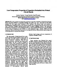
Figure 1.
Prototype HT-300 capacitors: (left) 200V components, left to right, 100nF, 10μF, and 1μF; and (right) 500V components, left to right, 1.5μF, 100nF, and 2μF.
advanced power electronics. Our goal was to develop a dielectric optimized for use with SiC-based electronics that had a high permittivity and low dielectric loss at 300°C. This was accomplished by developing one of the highest temperature ferroelectric relaxor dielectrics ever reported. Normal ferroelectrics are characterized by very sharp peaks in their dielectric constant vs. temperature curves that correspond to ferroelectric-to-paraelectric phase transitions (i.e. the Curie temperature). Below the Curie temperature these materials are ferroelectric and often have dielectric constants on the order of 500 to 5000 over a broad temperature range. However, ferroelectrics often exhibit very high losses under AC driving conditions due to reorientation of the ferroelectric domains. On the other hand, relaxor ferroelectrics have broad, diffuse ferroelectric-to-paraelectric transitions. Near the transition temperature, the ferroelectric domains are nano-sized with unstable polarization and low loss under high AC driving conditions. Thus, our strategy was to take a normal high-temperature ferroelectric composition and modify it into a relaxor ferroelectric for high temperature power capacitors. In general, a material that is initially ferroelectric can be modified into a relaxor by doping with cations that perturb the translational symmetry of the lattice. Dopants can have larger sizes, different valences, or create associated ionic vacancies on either the cation or anion sites. If the local strain or electric fields associated with these point defects are sufficiently strong they interact with the spontaneous dipolar polarization of the ferroelectrics and fundamentally alter the polarization mechanism. The long-range dipolar ordering that characterizes the normal ferroelectric material, and produces domains with a specific crystallographic relationship, is broken down by these local interactions, and frustrated dipolar microregions exist instead. Along with this radical change in polarization distribution, dynamic fluctuations in the orientations of these microregions are also introduced. The net result in terms of properties, and highly attractive to capacitor applications, is a broad or ‘diffuse’ transition, that has a frequency dependence to what is now called the Curie maximum (Tmax). The performance of this new dielectric (referred to as HT-300) was demonstrated in the form of prototype multilayer ceramic capacitors (MLCCs). The prototypes were designed to be rated at 200-500V with values ranging from 100nF to 10μF at 300°C, including: 0.1μF/500V, 1.5μF/500V, 1μF/200V, and 10μF/200V. This paper will describe our work to characterize the performance and lifetime of these components. Standard lifetime testing and highly accelerated lifetime testing [HALT] were used to modify the device designs to maximize lifetime. Theses tests along with dielectric breakdown strength measurements were the primary feedback method for determining voltage rating and dielectric layer thickness in the MLCC design process.
Figure 3. Temperature dependence of the polarization for HT-300 capacitors. (Left) remnant polarization and pyroelectric coefficient, and (right) P-E hysteresis loops for 25oC, 200oC, and 300oC (±600V).
Experimental Several pieces of equipment have been built or modified to accommodate testing of these high temperature dielectrics. Most of the high temperature electrical measurements (including: impedance, breakdown, and voltage stability) were conducted in a specially-built sample stage. This small furnace can simultaneously measure three samples at temperatures ranging from 25°C to 750°C. A second measurement system was re-designed to allow for current-based measurements such as I-V curves, P-E hysteresis, and discharge curves. It allows for simultaneous measurement of up to eight samples at temperatures from -180°C to 450°C. An existing ‘high’ temperature HALT system, capable of operating up to ~200°C, was modified to allow measurements at temperatures up to 400°C and voltages up to 500VDC. DC blocking circuits were used to protect the impedance analyzers and picoammeters during high voltage measurements (up to 4kV). Some other equipment used extensively throughout this work were various LCR meters (HP4284, Agilent), impedance analyzers (HP4194A, Agilent), a modified Sawyer-Tower circuit for polarization (P-E) hysteresis, power supplies (Model 610, Trek), and picoammeters (HP4140, Agilent). The prototype multilayer capacitors were fabricated by standard techniques. The dielectric powder was tape cast to obtain 1.5 - 2mil (38 - 51μm) sheets using a CAM-22 casting machine. The tape was cut into 5x5inch squares before screen printing the platinum internal electrodes (Ferro E-1192). Multilayers were laminated in a warm isostatic press. After
Figure 2. Temperature dependence of the capacitance and loss for two of the 500V MLCCs (left) 100nF and (right) 1.5μF.
sintering, fired-on silver terminations (Dupont 7095) were applied to the MLCCs. The layer
Figure 4.
(Left) voltage saturation for three 100nF/500V MLCCs measured at 300oC and 10kHz, and (right) RC constant.
thickness was optimized for either 200V (33μm) or 500V (198μm) operation and the active area per layer was fixed at either 50mm2 or 250mm2.
Results and Discussion The transition temperature of HT-300 is 232°C with a maximum dielectric constant of 11,000 at 1kHz. At 300°C, the dielectric constant is ~7600, the loss is ~0.96% with voltage saturation of ~90% at 10kV/cm and resistivity of >1010 Ω-cm. The material is ferroelectric at room temperature as indicated by the large remnant polarization at room temperature (Figure 3). The polarization and associated hysteresis losses decrease with temperature and the material depolarizes at ~175°C. The volumetric efficiency of the HT-300 dielectric is 1.806μF/cm3 at the 198μm thickness required for 500V operation. In the form of an MLCC the volumetric efficiency of the packaged 1.5μF/500V component was estimated to be 0.985μF/cm3 at 300°C. Values calculated for the 200V layer thickness (33μm) are significantly larger. For the dielectric itself the value was 10.836μF/cm3. After packaging the value was 15.873μF/cm3 for the 1μF/200V prototypes. The application of voltage reduces the dielectric constant and hence the volumetric efficiency of ferroelectric materials. In the case of the undoped HT-300 material this ‘voltage saturation’ was about ~2% at 10kV/cm; however, after doping to improve reliability, this increased to about 10%. After optimizing the thickness to 198μm for an operating field of 25kV/cm at 500V, the value further increased to 35%; the 200V parts experience fields of 60kV/cm resulting in voltage saturation values of about 75% (Figure 4). Using a series internal electrode design, the voltage saturation level could be reduced to 1010 at 300°C to >1014 Ω-cm at room temperature. The insulation resistance (or RC constant) was determined from these two experiments. The value decreased from 20,000Ω-F at room temperature to 10Ω-F at 300°C. These values of resistivity and insulation resistance are orders of magnitude higher than commercially available dielectrics.
log voltage (V)
10 1 0.1 0.01 0.001 1.00E+02
1.00E+03
1.00E+04 1.00E+05
1.00E+06
log absolute time (sec) Figure 6.
HALT measurement 100nF/500V capacitors at 400oC with an applied voltage of 500V. (The measured HALT voltage is related to the leakage current through the capacitor.)
The dielectric breakdown strength (DBS) and reliability of the MLCCs were also studied. Weibull statistics were used to estimate the characteristic breakdown field for the MLCCs. For the breakdown study, the cumulative probability was put into linear form and the characteristic breakdown field was determined. Figure 5 is a plot of the cumulative probability vs. the breakdown field at 300°C for the 100nF/500V parts. The characteristic breakdown field was 85 kV/cm (1684V) and the Weibull modulus or scalability of the data was ~19.1. From Figure 5 and data from other designs it is apparent that only one failure mode is present. Data collected on a 100nF/200V design showed a breakdown voltage of 215kV/cm (708V). Reliability tests were performed on a highly accelerated life test or HALT circuit at the operational conditions of 200VDC at 300°C for the 200V capacitors. The isothermal HALT equation is: n
n
⎡V ⎤ t 1 ⎡V 2 ⎤ E ⎡1 1⎤ t = ⎢ ⎥ exp A ⎢ − ⎥ → 1 = ⎢ 2 ⎥ × constant t 2 ⎣ V1 ⎦ K ⎣ T1 T2 ⎦ t 2 ⎣ V1 ⎦
Figure 5.
Weibull analysis of the dielectric breakdown strength of the 100nF/500V MLCCs at 300oC, characteristic breakdown strength shown is 1684V (85kV/cm). (Sample size was 24 pieces.)
where the subscripts 1 and 2 describe the test conditions, t is the median time to failure, V is voltage, n is the voltage acceleration factor, EA is the activation energy for failure, K is the Boltzmann constant, and T is absolute temperature. The acceleration factor, n, was calculated by measuring MLCCs of different layer thickness. An acceleration factor of 2 was found for the MLCCs, similar to values found in the literature of comparable relative permittivity materials. An analysis of the change in mean failure time (i.e. the time at which 50% of the parts failed, t50) with layer thickness showed that the optimum 500V layer thickness was ~200μm. The mean time to failure of several commercially available X7R and NPO capacitors were also determined under similar conditions. It was shown that the HT-300 MLCCs had a t50 nearly 25 times greater than the X7R and NPO materials at 300°C. HALT measurements showed no failures at 300°C and 500V after 12days for any of the 500V rated parts. A second set of HALT measurement were then conducted at 400°C and 500V (Figures 6). These MLCCs showed no failures after over 333hours. For comparison, no X7R or NPO type capacitors survived more than a few hours at 300°C at 200V. The voltage dependence of the dielectric properties was also measured as a function of temperature for the 100nF/500V parts (Figure 7). This data was collected by applying a voltage sweep (0V to +600V to -600V to +600V to 0V) to the capacitor at temperatures from 30°C to 460°C. As mentioned above HT-300 is ferroelectric at room temperature as indicated by the large remnant polarization at room temperature and the material depolarizes at ~175°C (Figure 3). This behavior can be seen in the first two figure insets and the discontinuity in capacitance near 175°C. The operating temperature was originally intended to be within a few degrees of 300°C. However, this data shows that the range could extend from 175°C to 350°C, and since the ferroelectric hysteresis is not large, possibly extending to near or below room temperature. Further, it is also evident that the temperature coefficient of capacitance is significantly reduced under the influence of a 500VDC bias as compared to the unbiased state.
Summary A series of new dielectrics have been developed that are capable of operating over a very wide range of temperatures. In this paper we have described one of these dielectrics, HT-300, which was designed for operation near 300°C as required for specific applications. However, they were shown to operate well at temperatures ranging from room temperature to over 400°C.
Figure 7.
Temperature and voltage dependence of a 100nF/500V MLCC measured at 10kHz heating. Insets are isotherms showing capacitance change with applied voltage, scale: y: 10nF/div and x: 300V/div (voltage sweep at each temperature is: 0V to +600V to -600V to +600V to 0V). Note the ferroelectric ‘phase transition’ at ~175oC.
The performance of the 500V/100nF parts has been outstanding. Lifetime, operating voltage, and resistivity of these capacitors are all significant improvements over available re-rated X7R/X8R/NPO and other high temperature formulations. Possibly the most important figure of merit is the RC constant, often expressed as the insulation resistance. The HT-300 dielectric, operating at 500V, outperforms the commercially available component (operating at only 200V) by 10 times at 200°C and over 100 times by 300°C. Lifetime tests have also shown that the COTS components only survive ~4hours at 300°C with 200VDC applied, while no failures where observed for the HT-300 prototypes after 12days at 400°C with 500VDC applied.
Acknowledgements This work was supported, in-part, by SBIR grants from NASA Glenn Research Center (Contract nos. NNC04CA16C and NNC04CA71C).
References [1] E.F. Alberta, et. al., Proceedings of the 24th CARTS, 69-72 (2004). [2] High Temperature Electronics, Ed. P. McCluskey et. al., CRC Press, New York (1997).