Neuromodulation: Technology at the Neural Interface Received: October 10, 2011
Revised: April 12, 2012
Accepted: May 23, 2012
(onlinelibrary.wiley.com) DOI: 10.1111/j.1525-1403.2012.00481.x
High-Resolution Modeling Assisted Design of Customized and Individualized Transcranial Direct Current Stimulation Protocols Marom Bikson, PhD*, Asif Rahman, MS*, Abhishek Datta, PhD†, Felipe Fregni, MD, PhD†, Lotfi Merabet, OD, PhD‡ Objectives: Transcranial direct current stimulation (tDCS) is a neuromodulatory technique that delivers low-intensity currents facilitating or inhibiting spontaneous neuronal activity. tDCS is attractive since dose is readily adjustable by simply changing electrode number, position, size, shape, and current. In the recent past, computational models have been developed with increased precision with the goal to help customize tDCS dose. The aim of this review is to discuss the incorporation of highresolution patient-specific computer modeling to guide and optimize tDCS. Methods: In this review, we discuss the following topics: 1) The clinical motivation and rationale for models of transcranial stimulation is considered pivotal in order to leverage the flexibility of neuromodulation; 2) the protocols and the workflow for developing high-resolution models; 3) the technical challenges and limitations of interpreting modeling predictions; and 4) real cases merging modeling and clinical data illustrating the impact of computational models on the rational design of rehabilitative electrotherapy. Conclusions: Though modeling for noninvasive brain stimulation is still in its development phase, it is predicted that with increased validation, dissemination, simplification, and democratization of modeling tools, computational forward models of neuromodulation will become useful tools to guide the optimization of clinical electrotherapy. Keywords: Electrical stimulation, FEM, fMRI, head model, lesion, modeling, neuromodulation, skull defects, stroke, tDCS, TMS, traumatic brain injury Conflict of Interest and Sources of Funding Statement: Dr. Datta is cofounder of Soterix Medical. The City University of New York has patent applications in Dr. Datta’s name on brain stimulation. Dr. Bikson is funded by the National Institutes of Health (nos. S06 GM008168 NS054783, CRCNS 41771), the Andy Grove Foundation, and the Wallace H Coulter Foundation. The City University of New York has patent applications in Dr. Bikson’s name on brain stimulation. Dr. Bikson is cofounder of Soterix Medical.
INTRODUCTION TO COMPUTATIONAL MODELS OF NONINVASIVE NEUROMODULATION
306
Transcranial electrical stimulation is a promising tool in rehabilitation based on the growing evidence that delivery of current to specific brain regions can promote desirable plastic changes (1,2). Of particular interest are neurostimulation modalities that are lowcost, portable, and simple to implement. Furthermore, stimulation should be applied using low intensity current in a manner that is safe, well tolerated, and can be delivered concurrently with physical rehabilitation and other therapies. Currently, transcranial direct current stimulation (tDCS) has been gaining considerable interest because it possesses all these desired qualities (3). In contrast to pharmacotherapy, noninvasive electrotherapy offers the potential for both anatomically specific brain activation and complete temporal control since electricity is delivered at the desired dose instantly and there is no electrical “residue” as the generated brain current disappears when stimulation is turned off. Thus, tDCS can be customized and individualized to specific brain targets in ways not possible with other interventions in order to optimize a particular rehabilitative outcome. Specifically, the “dose” www.neuromodulationjournal.com
of electrotherapy (see (4) for definition) is readily adjustable by determining the location of electrodes (which determines spatial targeting) and selecting the stimulation waveform (which determines the nature and timing of neuromodulation). Indeed, a single programmable electrotherapy device can be simply configured to provide a diversity of dosages. Though this flexibly underpins the utility of neuromodulation, the myriad of potential dosages (stimulator settings and combinations of electrode placements) makes the
Address correspondence to: Marom Bikson, PhD, 160 Convent Ave., Steinman Hall, Rm. #403B, New York, NY 10031, USA. Email:
[email protected] * Department of Biomedical Engineering, The City College of New York of CUNY, New York, NY, USA † Laboratory of Neuromodulation, Spaulding Rehabilitation Hospital, Harvard Medical School, Boston, MA, USA; and ‡ Vision Rehabilitation Center, Department of Ophthalmology, Massachusetts Eye and Ear Infirmary, Harvard Medical School, Boston, MA, USA For more information on author guidelines, an explanation of our peer review process, and conflict of interest informed consent policies, please go to http:// www.wiley.com/bw/submit.asp?ref=1094-7159&site=1
© 2012 International Neuromodulation Society
Neuromodulation 2012; 15: 306–315
MODELING ASSISTED OPTIMIZED TDCS NEUROMODULATION
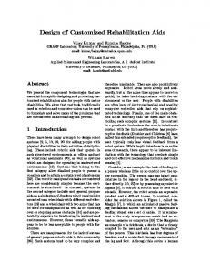
Figure 1. Role of computational models in rational electrotherapy: (left) Neuromodulation is a promising therapeutic modality as it allows affecting the brain in a way not possible with other techniques and a high degree of individualized optimization. The goal of computational models is to assist clinicians in leveraging the power and flexibility of neuromodulation. (right) Computational forward models are used to predict brain current flow during transcranial stimulation to guide clinical practice. As with pharmacotherapy, electrotherapy dose is controlled by the operator and leads a complex pattern of internal current flow that is described by the model. In this way, clinicians can apply computational models to determine with dose will activate (or avoid) brain regions of interest.
optimal choice very difficult to readily ascertain. The essential issue in dose design is to relate each externally controlled dose with the associated brain regions targeted (and spared) by the resulting current flow—and hence the desired clinical outcome. Computational forward models aim to provide precisely these answers to the first part of this question (Fig. 1), and thus need to be leveraged in the rational design, interpretation, and optimization of neuromodulation. The precise pattern of current flow through the brain is determined not only by the stimulation dose (e.g., the positions of the electrodes) but also by the underlying anatomy and tissue properties. In predicting brain current flow using computational models, it is thus important to precisely model both the stimulation itself and the relevant anatomy upon which it is delivered on an individual basis. The latter issue remains an area of ongoing technical development and is critical to establishing the clinical utility of these models (5). For example, cerebral spinal fluid (CSF) is highly conductive (a preferred “super highway” for current flow) such that details of CSF architecture profoundly shape current flow through adjacent brain regions (see later discussion). Especially relevant for rehabilitative applications is the recognition that individual anatomical idiosyncrasies can result in significant distortions in current flow. This is particularly apparent when skull defects and brain lesions occur. The final section of this review highlights the nature and degree of distortions in brain current flow produced by defects and lesions, as well as dose considerations for susceptible populations such as children.
METHODS AND PROTOCOLS IN THE GENERATION OF COMPUTATIONAL FORWARD MODELS OF TDCS
www.neuromodulationjournal.com
1. Demarcation of individual tissue types (masks) from highresolution anatomical data (e.g., magnetic resonance imaging (MRI) slices obtained at 1 mm slice thickness) using a combination of automated and manual segmentation tools. Specifically, from the perspective of stimulating current flow, it is necessary to distinguish tissues by their resistivity. A majority of effort in the development and implementation of models has involved this step (see also next section). The number and precision of the individual masks obtained is pivotal for the generation of accurate 3D models in order to capture critical anatomical details that may influence current flow. 2. Modeling of the exact physical properties of the electrodes (e.g., shape and size) and precise placement within the segmented image data (i.e., along the skin mask outer surface).
© 2012 International Neuromodulation Society
Neuromodulation 2012; 15: 306–315
307
During tDCS, current is generated in the brain. Because different electrode montages result in distinct brain current flow, researchers and clinicians can adjust the montage to target or avoid specific brain regions in an application specific manner. Though tDCS montage design often follows basic rules of thumb (e.g., increased/ decreased excitability under the anode/cathode electrode), compu-
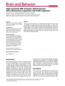
tational forward models of brain current flow provide more accurate insight into detailed current flow patterns and in some cases can even challenge simplified electrode-placement assumptions. For example, clinical studies are designed by placing the anode electrode directly over the target region desired to be excited, while the cathode electrode is placed over a far removed region from the target to avoid unwanted reverse effects. This region could be the contralateral hemisphere or in some cases even extracephalic locations like the neck, shoulder, or the arm. Researchers have used smaller stimulation electrode sizes and bigger reference electrode sizes to offset the focality limitations of tDCS. With the increased recognized value of computational forward models in informing tDCS montage design and interpretation of results, there have been recent advances in modeling tools and a greater proliferation of publications (5–22). In considering new electrode montages, and especially in potentially vulnerable populations (e.g., skull damage, children), forward models are the main tool used to relate the externally controllable dose parameters (e.g., electrode number, position, size, shape, current) with resulting brain current flow. While the specific software applications can vary across groups, in general, the approach and workflow for model generation follow a similar pattern (Fig. 2). The steps for generating high-resolution (anatomically specific) forward models of noninvasive neuromodulation are adapted from extensive prior work on computational modeling. These involve:
BIKSON ET AL.
Figure 2. Imaging and computational work-flow for the generation of high-resolution individualized models: Though the specific processes and software packages will vary across technical groups and applications, in each case high-resolution modeling initiated with precise anatomical scans that allow demarcation of key tissues. Tissues with distinct resistivity are used to form “masks.” These masks along with the representation of the physical electrodes are “meshed” to allow Finite Element Methods calculations. The boundary conditions (generally simply reflecting how the electrodes are energized) and the governing equations (related to Ohm’s law) are well established. The reproduction of the stimulation dose and the underlying anatomy thus allow for the prediction of resulting brain current. These current flow patterns are represented in false-color map and analyzed through various post-processing tools.
3. Generation of accurate meshes (with a high quality factor) from the tissue/electrode masks while preserving resolution of subject anatomical data. The generation of meshes is a process where each mask is divided into small contiguous “elements” which allow the current flow to then be numerically computed—hence the term “Finite Element Method” stimulations. 4. Resulting volumetric meshes are then imported into a commercial finite element solver. 5. At this step, resistivity is assigned to each mask (every element in each mask) and the boundary conditions are imposed including the current applied to the electrodes. 6. The standard Laplacian equation is solved using the appropriate numerical solver and tolerance settings. 7. Data are plotted as induced cortical electric field or current density maps (Fig. 2).
308
Though each of the above steps is required for high-resolution modeling, there remains technical expertise and hence variation in protocols across groups and publications (5–22). These variations are relevant to clinical practice only in the sense that they change predictions in current flow that meaningfully effect dose decisions. The sources and impact of these variations is addressed in the next section. Initial models of transcranial direct current flow assumed simplified geometries such as concentric spheres that could be solved analytically as well as numerically (6,8). Miranda et al. (6) looked specifically at tDCS montages while Datta et al. (8) compared focality across multiple small electrode configurations and proposed configurations to achieve targeted modulation. Such concentric sphere models are useful to address generic dose questions such as the global role of interelectrode distance, electrode montage, or the relationship between electrode and brain current density, prewww.neuromodulationjournal.com
cisely because they exclude regional anatomical differences. More realistic models started to include explicit representation of human anatomy (7). Wagner et al. (7) was the first computer-aided design rendered head model where current density distributions were analyzed for various montages including healthy vs. cortical stroke conditions. Oostendorp et al. (9) was the first to consider anisotropy in the skull and the white matter. Datta et al. (11) published the first model of tDCS with gyri resolution, illustrating the importance of anatomical precision in determining complex brain current flow. Suh et al. (13) concluded that skull anisotropy causes a large shunting effect and may shift the stimulated areas. Sadleir et al. (15) compared modeling predictions of frontal tDCS montages to clinical outcomes. Datta et al. (14) studied the effect of tDCS montages on traumatic brain injury (TBI) and skull defects. Fine resolution of gyri/sulci lead to current “hotspots” in the sulci, thereby reinforcing the need for high-resolution modeling (16). An open-source head model comprising of several different tissue types was adapted to analyze current flow through cortical, subcortical, and brain stem structures (18). Such models help determine whether current of sufficient magnitude reaches the deeper subcortical structures. Recent studies have attempted to more directly link clinical outcomes and model predictions—and thus validate model utility. Clinical evaluation was combined with model predictions to investigate the effects of different montages in clinical conditions such as fibromyalgia (20). Recently, patient-specific models have been used to retrospectively analyze the therapeutic success of a given experimental stimulation montage (5) and compare model predictions with patterns of activation revealed by functional MRI (fMRI) (19). Modulation of subcortical and brain stem structures were analyzed in a migraine study (22). These example applications open the door for potentially customizing tDCS on a subject to subject basis within
© 2012 International Neuromodulation Society
Neuromodulation 2012; 15: 306–315
MODELING ASSISTED OPTIMIZED TDCS NEUROMODULATION
Table 1. Synopsis of Numerical tDCS Computer Models. Study
Masks
Electrode montage
4 tissue models 4
4 montages 6 montages
5
Healthy and stroke models with varied montages
5
C3—SO montage
Datta et al. (11) Suh et al. (13)
4 5
Datta et al. (10)
4
Sadleir et al. (15)
11
Datta et al. (14)
4
Bikson et al. (17) Salvador et al. (16) Parazzini et al. (18) Mendonca et al. (20)
7 5 26 unique tissue types 8
Halko et al. (19)
7
C3—SO and high-definition (HD) montages. C3—C4 montage using point source stimulation electrodes Tissue temperature increases of C3—SO montage and HD montage F3—SO and F4—SO montage and comparison with reported clinical outcomes in literature Effect of skull defects and skull plates for C3—SO and O1—SO montages C3—SO and C3-contralateral mastoid. C3—SO montage Analysis of current flow through cortical, subcortical, and brain stem regions for C3—SO montage C3-extracephalic, SO-extracephalic, and C3-SO montages Oz—Cz montage
Datta et al. (5)
8
DaSilva et al. (22)
15
Turkeltaub et al. (21)
8
Concentric sphere Miranda et al. (6) Datta et al. (8) CAD rendered Wagner et al. (7) MRI derived Oostendorp et al. (9)
Bonsai—Model Solution Analyzer http://www. neuralengr.com/bonsai
6–8
Additional methods
Retrospective analysis comparing experimental outcome with model predictions. LFC-RS, LFC-contralateral mastoid, LFC-SO, and RFC-LS C3—SO montage analysis of current flow through subcortical structures Analysis of left pTC and right pTC montage in dyslexia study Healthy and stroke model with varied montages
Anisotropic conductivities for skull and white matter. Model derived from Wolters et al. (40) High-resolution with gyri-sulci topography. Anisotropic conductivity for white matter
Effect of “return electrode” position and size High-resolution gyri–sulci model Model derived from virtual family open-source data base Correlation of clinical effects in a fibromyalgia study with model predictions Patient-specific visual stroke model of a hemianopia patient undergoing tDCS Correlation of high-resolution current flow model predictions with fMRI Patient-specific left hemisphere stroke model of a tDCS responder Correlation of clinical effects in a chronic migraine study
Online data base of solved patient-specific head models. Overlaid views of 2D MRI scans and model solutions
Summary of tDCS forward head models using Finite Element Methods techniques. Head models have progressed from being spherical based to being MRI derived. The most recent ones have employed patient-specific models. The second, third, and fourth columns list number of tissue types, the montage used, and particular model specifics, respectively. C3, C4, F3, F4, O1, Oz, Cz correspond to 10/20 electroencephalogram system; SO, contralateral supra-orbital; LFC, left frontal cortex; RFC, right frontal cortex; RS, right shoulder; LS, left shoulder; pTC, posterior temporal cortex.
the clinical setting. Table 1 summarizes the various montages explored in published literature focused on tDCS. For clinicians interested in using computational forward models to inform study design or interpretation several options are available: • a collaboration with a modeling group (21) or a company can allow for customized exploration of montage options • referencing existing published reports or data bases (Table 1) for comparable montages (with careful consideration of the role of individual variation and other caveats presented in the next section) • recently, a process where a desired brain region can be selected and the optimized electrode montage is proposed within a single step has been developed (23).
www.neuromodulationjournal.com
PITFALLS AND CHALLENGES IN THE APPLICATION AND INTERPRETATION OF COMPUTATIONAL MODEL PREDICTIONS Computational models of tDCS range in complexity from concentric sphere models to high-resolution models based on individuals MRIs (as described above). The appropriate level of modeling detail depends on the clinical question being asked, as well as the available computational resources. Whereas simple geometries (e.g.,
© 2012 International Neuromodulation Society
Neuromodulation 2012; 15: 306–315
309
Even as increasingly complex and resource expensive modeling tools are developed, parallel efforts to simplify and automate (high-
throughput) model workflow are needed to facilitate clinical translation. If tDCS continues to emerge as an effective tool in clinical treatment and cognitive neuroscience, and concurrent modeling studies emphasize the need for rational (and in cases individualized) dose decisions, then it will become incumbent for clinical teams establishing new paradigms to understand the applications (and limitations) of computational forward models (24).
BIKSON ET AL. spheres) may be solved analytically (25), realistic geometries employ numerical solvers, namely Finite Element Methods (FEM). Regardless of complexity, all forward models share the goal of correctly predicting brain current flow during transcranial stimulation to guide clinical therapeutic delivery. Special effort has been recently directed toward increasing the precision of tDCS models. However, it is important to note that increased model complexity does not necessarily equate with greater accuracy or clinical value. To meaningfully guide clinical utility, attempts to enhance model precision must rationally balance detail (i.e., complexity) and accuracy. 1. Beginning with high-resolution anatomical scans, the entire model workflow should preserve precision. Any human head model is limited by the precision and accuracy of tissue segmentation (i.e., “masks”) and of the assigned conductivity values. One hallmark of precision is that the cortical surface used in the final FEM solver should capture realistic sulci and gyri anatomy. 2. Simultaneously, a priori knowledge of tissue anatomy and factors known to influence current flow should be applied to further refine segmentation. Particularly critical are discontinuities not present in nature that result from limited scan resolution; notably both unnatural perforations in planar tissues (e.g., ventricular architecture, discontinuities in CSF where brain contacts skull, misrepresented skull fissures) and microstructures (e.g., incomplete or voxelized vessels) can produce significant deviations in predicted current flow.
310
Moreover, because of the sensitivity of current flow to any conductivity boundary, increasingly detailed segmentation (e.g., globe of the eye and related structures, glands, and deeper midbrain structures) without reliable reported human conductivity values in literature (especially at static frequency) may also lead to errors. It is worth noting that the respective contribution of the automated/ manual interventions also depends on: 1) sophistication of the particular data base or automated algorithm employed since they are usually not optimized for forward transcranial modeling (5) and 2) the need for identification of anomalies in suspect populations like skull defects, lesions, shunts, etc. Thus, addition of complexity without proper parameterization can evidently decrease prediction accuracy. An improper balance between these factors can introduce distortions in predicted brain current flow. Divergent modeling methods illustrate existing outstanding issues, including: 1) detail in physically representing the stimulation electrodes and leads, including shape and material (11), and energy source boundary conditions; 2) differences between conductivity values derived from static resistivity measures and those extrapolated from 10 Hz data; 3) sufficient caudal head volume representation (such that the caudal boundary condition does not affect relevant model prediction), including potential use of synthetic volumes (5,20); 4) optimal imaging modalities/sequences to differentiate among tissue types; 5) appropriate incorporation of anisotropy (from diffusion tensor imaging); 6) suitability of existing image segmentation algorithms (generally developed for other applications) (26); 7) the degree and nature of manual correction; 8) the adequacy of the numerical solver (especially when making detailed predictions at tissue boundaries); 9) detail in segmenting true lesion borders (5) vs. idealized defects; and 10) the need for parametric and interindividual analysis (see below). The optimization of the above issues remains open questions and inevitably reflects available resources (e.g., imaging, computational, anatomical expertise) and the specific clinical question addressed in each modeling effort. www.neuromodulationjournal.com
Even as computational and engineering groups continue developing more modeling sophistication, clinicians must be aware of the limitations in any modeling approach and the inevitability of technical methodology effecting the predictions made. Assuming accurate and precise representation of all tissue compartments (anatomy, resistivity, anisotropy) relevant to brain current flow, it is broadly assumed that using modern numerical solvers that the resulting prediction is independent of the numerical technique used. Our own experience across various commercial solvers confirms this implicit assumption when meshes are of sufficient detail—precise description in methods (use of publicly available programs) and representation of resulting mesh density and quality (in figures or methods) as well as tests using various solvers provides explicit control for errors generated by the computation itself. Literature regarding forward modeling—or more broadly the dissemination of modeling analysis to the clinical hands—introduces still further issues in regard to 1) interpretability, reproducibility, and accuracy (tissue masks) and 2) graphical representation of regions of influence (degree of “activation”). As there is no standard protocol for tissue imaging or segmentation, diversity in the nature of resulting tissue masks will invariably influence predicted current flow. As such, it is valuable to illustrate each 3D tissue mask in publication methods and/or classified serial sections. In regard to representation of relative activation, studies employ either maps of current density (unit of A/m2) or electric field (unit of V/m). Because the two are related linearly by local tissue resistivity, when plotting activation in a region with uniform resistivity (e.g., the cortical surface), the spatial profile is identical. When plotting activation across tissues (e.g., coronal section), current density may be advantageous to illustrate overall brain current flow. However, the electric field in the brain is directly related to neuronal activation (e.g., for varied resistivity, the electric field, but not current density, provides sufficient information to predict activation). Despite best efforts, figure preparation invariably restricts tissue mask perspectives and comprehensive display of volumetric current flow, which can be supplemented with online data publication (http://www. neuralengr.com/bonsai). When interpreting simulation predictions, it is important to recognize that the intensity of current flow in any specific brain region does not translate in any simple (linear) manner to the degree of brain activation or modulation (even when considering current direction). Moreover, recent neurophysiological studies indicate changes in “excitability” may not be monotonic with stimulation (27). For example, increasing stimulation amplitude or duration can invert the direction of modulation, as can the level of neuronal background activity (28). However, to a first approximation, it seems reasonable to predict that regions with more current flow are more likely to be “effected” by stimulation while regions with little or no current flow will be spared the direct effects of stimulation. As a first step to understand mechanism of action of tDCS, a relationship between model predicted regional current flow and changes in functional activation was recently demonstrated (19). The “quasiuniform” assumption considers that if the electric field (current density) is uniform on the scale of a region/neuron of interest, then “excitability” may be modulated with local electric field intensity (29) (see discussion in Datta et al. (8) and Miranda et al. (30)). Though efforts to develop suitable biophysical detailed models considering myriad of neurons with distinct positions and morphologies or“continuum” approximations (31) of modulation are pending, the current state of the art requires (implicit) application of the “quasiuniform” assumption.
© 2012 International Neuromodulation Society
Neuromodulation 2012; 15: 306–315
MODELING ASSISTED OPTIMIZED TDCS NEUROMODULATION Much of the theoretical and technical foundations for modeling brain stimulation were established through modeling studies on peripheral nerve stimulation (“Functional Electrical Stimulation,” FES) and then Spinal Cord Stimulation and Deep Brain Stimulation (DBS) (reviewed in: McIntyre et al. (32–34)). In light of the challenges to tDCS modeling cited above, we note that FES and DBS use electrodes implanted in the body such that relatively small volume of brain is needed to be modeled, and with none of the complication associated with precisely representing gross anatomy (e.g., skull, fat, CSF, etc.). From the perspective of computational burden, the volume, number of masks, and mask complexity results in tDCS models with >5 million elements, compared with