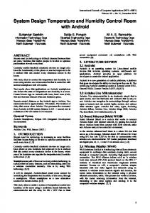
Recent Advances in Environmental and Earth Sciences and Economics
Humidity and Temperature Control of a Metrology Laboratory Jorge M. Jaimes Ponce, Jesús U. Liceaga C., Irma I. Siller A. and Enrique Arévalo Zamudio.
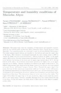
implemented using the microcontroller PIC16F877A [1] from which one input port is used to connect a keyboard and one output port to connect a liquid crystal display (LCD). Also, six A/D input channels were used to sense in three different positions the humidity and temperature -three channels for each variable-. One of the most important characteristics of the control system is that from the sensing of the humidity and temperature in three different locations of the laboratory it is possible to obtain a better measurement of these variables using the average of the three measurements, Figure 1. Moreover, the system is capable of detecting the number of sensors that are actually connected allowing the control system to keep operating even in the case of a failure of any sensor.
Abstract—In the industry there are situations in which a particular problem may require a low cost solution simple to design and manufacture rendering a system easy not only to operate but to repair and maintain. In this paper the design and implementation of a humidity and temperature control system for a metrology laboratory is presented. The control system must comply with the requirements of a metrology laboratory dedicated to the calibration and certification of industrial scales. A second requirement is that the control system must be designed using standard industrial components for both hardware and software. In this sense, the control system is based on the microcontroller PIC16F877A, the humidity and temperature sensor HMW61/71 and the well-known classical PID controller.
Keywords—Humidity and temperature control, PID control I. INTRODUCTION
M
ETROLOGY laboratories dedicated to the calibrations and certification of industrial and commercial scales require to operate under certain conditions regarding the humidity, temperature, air flow, airborne particles, etc. However, the most important variables are the humidity and the temperature. That is, this kind of laboratories must operate at 20°C±2% with a relative humidity of 50%±2%. Therefore, the control system focuses only in the regulation of the humidity and temperature within the laboratory. The control system reported in this paper is part of an industrial project which is subject to confidentiality in all the information concerning laboratory real time responses. Therefore, actual data of the laboratory cannot be published. Nonetheless, a general description of the designed control system together with important technical information is thoroughly described.
Fig. 1 Humidity and temperature Control System
To operate the electric heater and the ultrasonic humidifier it was necessary to design and construct 120 VCA power drivers. Another requirement from the client was that the system must keep a record of 4 measurements per hour during a period of 10 hours of operation for both the humidity and the temperature. This is important for quality control procedures. This information is stored in the microcontroller’s eeprom and after that it is sent to a PC by a serial port. Additional basic functions are performed using basic keys such as arrows –up, down, right, left-, stop, reset, and enter, as show in Figure 2. Finally, the control law is based on the well proved classical PID controller.
The control law to regulate de humidity and temperature was J. M. Jaimes-Ponce is with the Electronic Department of the UAMAzcapotzalco, Av. San Pablo 180 C.P. 02200, México (e-mail:
[email protected]). J. U. Liceaga-Castro is with the Electronic Department of the UAMAzcapotzalco, Av. San Pablo 180 C.P. 02200, México (phone: 52-5553189041 ; e-mail:
[email protected]). I. I. Siller-Alcalá is with the Electronic Department of the UAMAzcapotzalco, Av. San Pablo 180 C.P. 02200, México (e-mail:
[email protected]). E. Arévalo-Zamudio is with the Electronic Department of the UAMAzcapotzalco, Av. San Pablo 180 C.P. 02200, México (e-mail:
[email protected]).
ISBN: 978-1-61804-324-5
150
Recent Advances in Environmental and Earth Sciences and Economics
T: Sampling Period k: k-th sampling instant e(kT): error e(kT)=qd(kT)-q(kT) qd(kT)=Process output or controlled variable q(kT)=Set point or reference signal Kp=Proportional gain Td=Derivative gain Ti=Integral gain u(kT)= Controller output or control variable The energy supplied to the actuators –electric heater and ultrasonic humidifier- is periodic and bursty. That is, every 10sec the actuators will be powered by 120Vac during a period of time determined by the value of u(kT) which can be equal or less than 10sec
Fig. 2 Carátula del sistema de control de temperatura y humedad
Another alternative is to use commercial systems based on microcontrollers like Arduino. Arduino is a very economic microcontroller for which already exist many LabVIEW applications allowing the substitution of the data acquisition hardware. A final option is the use of the National Instruments software, from which the modulus for USB data acquisition are the cheapest and sufficient enough for many applications.
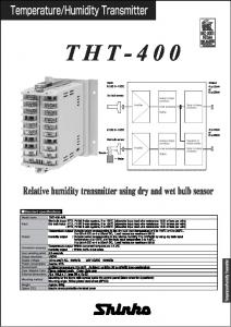
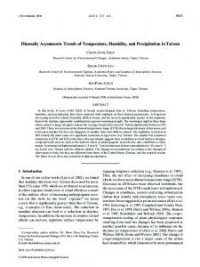
B. Sensors The temperature and the humidity sensor is the HMW61/71 from VAISALA, Figure 3. The HMW61/71 sensor includes two sensors: One to sense the temperature with an output between 4 to 20 mA for a variation of temperature between 20°C to 80°C, and the second to sense the humidity with an output between 4 to 20 mA for a variation of a relative humidity of 0 to 100%. The control system was constructed using three of this sensor, allocated in different positions inside the laboratory, to estimate the temperature and the humidity by the average of the measurements proportionated by the sensors. Moreover, the system can detect the number of sensors that are actually connected in order to adjust the average calculations. This is done by recalling that the minimum output signal value of the sensors is 4mA so if the sensors currents outputs are passed through 250 Ω resistances a minimum voltages, different from zero, are produced; hence, if at zero voltage is detected at the microcontrollers input ports this data is eliminated from the averaging.
II. GENERAL DESCRIPTION The most important characteristics of the control system are:
a) A PID controller for each variable b) It has 3 temperature sensors with output signals between 4 to 20 mA c) It has 3 humidity sensors with output signals between 4 to 20 mA d) Separate selection of Set Points for each variable e) A 120Vac electric heater f) A 120Vac ultrasonic humidifier g) Data storage with the possibility of data transmission to a PC via a serial port.
A. PID Controller Despite the existence of a great variety of control laws the classical PID [2] controller is still one of the most effective controllers for industrial applications. Also, it is a controller which is quite easy to implement. In the case of the humidity a temperature control system two digital PID controllers were implemented. The discrete definition of the PID controller is shown in Equation 1
Fig. 3 Temperature and humidity sensor HMW61/71
e(kT ) − e(kT − T ) T n = u (kT ) K p e(kT ) + Td + Σ e(kT ) (1) k T Ti
C. Set Point As any control system it is necessary to define a Set Point.
Where ISBN: 978-1-61804-324-5
151
Recent Advances in Environmental and Earth Sciences and Economics
In this case, through the system menu it is possible to define the temperature Set Point from 15°C to 25°C. This range was stablished according to the temperature requirements for scale calibrations. The ideal condition is 20°C±2% with a relative humidity (RH) of 50%±2%.
D. Actuators The temperature actuator is a 350 Watts resistance sufficient enough to heat a laboratory of 55m3. The resistance is powered with 120Vac via a triac. To drive the triac the microcontroller uses the optocoupler MOC3030. In the same way the humidifier is operated. It must be noted that the humidifier does not induce a temperature increment. Additionally, due to the physical characteristics of the actuators the control system actuates only when the error signals –Equation 1- are positive. In the case of negative error signals –when the temperature and/or the RH are above its Set Point values- the control system switch off and a cooling air condition system automatically is turned on.
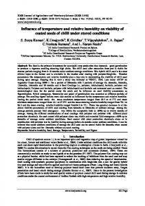
Fig. 4 Microcontroller PIC16F877A
B. Analog Inputs and A/D Conversion To capture the sensors analog signals the input A/D ports are used, specifically the inputs AN0 to AN5, from the microcontroller ports A and E. However, it is necessary to transform the sensors current outputs into voltage signals. This is done by connecting the precision 250 Ω resistances RT1, RT2 and RT3, as shown in Figure 5. By a straight forward calculation it is clear that with the minimum current of 4 mA, the minimum voltage will be 1 Volt.
E. Data storage, Serial Transmission and Timer An important client requisite for the system was that it must have the possibility to keep a record of the temperature and humidity. Hence, the system keeps 4 samples per hour during 10 hours –normal every day work load- per day with a total of 40 samples for each variable. This is controlled by a timer implemented in the same system. This information is important for quality control statistics. The data is recorded in the microcontroller eeprom and can be sent to a PC computer via serial port. In order to
III. HARDWARE A. Microcontroller
Fig. 5 Analog Inputs
In Figure 4, the microcontroller PIC16F876A is shown. This microcontroller has 8 A/D inputs, although only 6 are used. It also has several digital input/output ports, a keyboard and a liquid crystal display. Other important features of the PIC16F876A [1] are that it includes a modulus for serial communication and an eeprom memory. The purpose of using this internal nonvolatile memory is to reduce the need of external hardware resulting in a compact and dependable system.
ISBN: 978-1-61804-324-5
C. Serial Data Transmission The developed system has the necessary devices to connect to a PC. For the serial data transmission the microcontroller uses TTL signal –0V for the logic value “0” and 5V for the logic value “1”–. The PC uses the serial port RS232 [3] with 12V for the logic value “0” and -12V for the logic value “1”. Therefore, to connect the microcontroller to the PC the MAX232 circuit with the connector DB9 is used, Figure 7. The transmission characteristics are: 9600 bauds, without parity, 8 data bits and 1 stop bit.
152
Recent Advances in Environmental and Earth Sciences and Economics
PIC16F877A, the LCD, the optocouplers and the MAX232; the second is a 12V voltage source feeds the sensors.
Fig. 7 Connector DB9 and MAX232
Fig. 10 Voltage source
D. LCD and keyboard
IV. SOFTWARE
Two significant elements of the system are the liquid crystal display (LCD) and the keyboard, Figures 8 and 9. Thanks to these elements it is possible to interact with the system; for instance, it is possible to select and visualize the set points for the temperature and the RH or to establish the serial communication with a PC.
The development of the programming is based on the BASIC language for microcontrollers. BASIC is an excellent language due to its simplicity and because it allows high level applications programming, that is, it includes several functions or toolboxes. For instance, an important part of the program is the sensors detection, necessary to the average calculation of the temperature or RH variables. The BASIC program for this calculation is shown next.
Fig. 8 Some LCD screens
Fig. 9 Keyboard diagram
E. Voltage Source The voltage source provides two voltages: the first is a TTL 5V source necessary to operate all the digital electronics, the In the same way, the PID programming is shown next. ISBN: 978-1-61804-324-5
153
Recent Advances in Environmental and Earth Sciences and Economics
Fig. 12 LCD and keyboard
Part of the microcontroller programming includes additional options, such as: a) b) c) d)
Set the time Define the set points Define the when to initiate the data storage Initiate the serial communication
Fig. 14. Microcontroller and power boards
In Figure 11 LCD display of some the previous options are shown.
Fig. 15. Controller board and asensor
Fig. 11 LCD menu display
REFERENCES [1]
V. CONCLUSIONS
[2]
It was possible to design and construct a temperature and humidity control system for a metrology laboratory dedicate to the calibration and certification of scales. The control system fulfils the customer requirements: Low cost, easy to implement, operate and maintain, and constructed with standard industrial components. So far, the costumer reports that the system works as expected. Due to confidentiality issues it is not possible to present real time responses of the control system; nonetheless, in Figures 12-13 the hardware of the control system is shown.
ISBN: 978-1-61804-324-5
[3]
154
Martin P. Bates, “Interfacing PIC Microcontrollers: Embedded Design by Interactive Simulation”, Newnes, Second Edition, ISBN-13: 9780080993638. Katsuhiko Ogata, “Sistemas de control en tiempo discreto”, Pearson Educación, 1996. Jan Axelson, “Serial Port Complete, COM Ports, USB Virtual COM Ports, and Ports for Embedded Systems”, Lake View Research LLC, Second Edition 2007. ISBN 978-1931448-07-9.