Capital $590â730 per kW. 2. Variable $1â$2 per KWh ..... storage as of August 2013 totaled 24,600 MW, meaning a nearly 25-fold increase would be required to ...
Chapter 1
Hybrid Renewable Energy Systems
This chapter gives an elementary account of hybrid renewable energy systems (HRES). This type of system according to today’s demand on providing new source of electricity On-pick and storage of energy as a source of such demandable energy of electricity Off-pick. Hybrid renewable energy systems (HRES) are becoming popular as stand-alone power systems for providing electricity in remote areas due to advances in renewable energy technologies and subsequent rise in prices of petroleum products. A hybrid energy system, or hybrid power, usually consists of two or more renewable energy sources used together to provide increased system efficiency as well as greater balance in energy supply [1]. A renewable energy is energy that is collected from renewable resources, which are naturally replenished on a human timescale, such as sunlight, wind, rain, tides, waves, and geothermal heat. Renewable energy often provides energy in four important areas: electricity generation, air and water heating/cooling, transportation, and rural (off-grid) energy services.
1.1
Introduction to Hybrid Energy System
Hybrid energy systems combine two or more forms of energy generation, storage, or end-use technologies, and they can deliver a boatload of benefits compared with single source systems. The option of having variety in our day-to-day life could be considered as the spice of life; therefore, why limit ourselves to just one energy source or storage option? In these cases, hybrid energy systems are an ideal solution since they can offer substantial improvements in performance and cost reduction and can be tailored to varying end-user requirements. The energy storage system (ESS) in a conventional stand-alone renewable energy power system (REPS) usually has a short lifespan mainly due to irregular output of renewable energy sources. In certain systems, the ESS is oversized to reduce the stress level and to meet the intermittent peak power demand. A hybrid energy storage system (HESS) is a better solution in terms of durability, practicality, and © Springer International Publishing AG 2018 B. Zohuri, Hybrid Energy Systems, https://doi.org/10.1007/978-3-319-70721-1_1
1
2
1
Hybrid Renewable Energy Systems
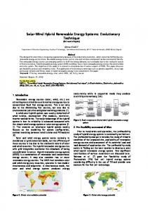
Fig. 1.1 Example of hybrid energy system (Courtesy of CSIROscope Corporation)
cost-effectiveness for the overall system implementation. The structure and the common issues of stand-alone REPS with ESS are discussed in this paper. This paper presents different structures of stand-alone REPS with HESS such as passive, semi-active, and active HESS. As there are a variety of energy storage technologies available in the market, decision matrixes are introduced in this paper to evaluate the technical and economic characteristics of the energy storage technologies based on the requirements of stand-alone REPS. A detailed review of the state-of-the-art control strategies such as classical control strategies and intelligent control strategies for REPS with HESS are highlighted. The future trends for REPS with HESS combination and control strategies are also discussed. Configurations could include renewable or nonrenewable energy sources, electrical and chemical energy storage, and fuel cells, often connected via a smart grid. They have the potential to dramatically reduce cost and emissions from energy generation and distribution for households but can be held back by the limitations of individual power generation or storage technologies—this may include cost, inconsistent supply (like interrupted solar on a cloudy day), etc. This means there is substantial demand for hybrid energy solutions to lower cost and improve efficiency while still meeting performance requirements. Figure 1.1 is a presentation of an example for hybrid energy system (HES), which is depicted by CSIROscope corporation. CSIROscope an Australian corporation researcher is claiming that there is now an increased availability of renewable and modular power generation and storage
1.1 Introduction to Hybrid Energy System
3
technologies such as batteries, fuel cells, and household solar. “These technologies are becoming cost competitive, but the key to greater use is to combine them in connected hybrid systems,” Dr. Badwal a researcher at this company says. He also goes a further step by stating that “By doing this, we can offer substantial improvements in performance and cost.” Consequently, the early player in this game will be ahead of their business and research ball, by keeping their heads together with industry partners, and the collaborative space could be used to share the benefits of emerging hybrid energy systems with industry and government to maximize the value of local energy sources. Having such foundation under consideration, the first questions that come to mind are what is hybrid system and the word hybrid stands for and what do we really mean by looking at a hybrid energy system as a new source of renewable energy and usage of such source during on-peak demand for electricity. Going toward the next century demand for more electricity is on rise, and consequently the on-peak hours of such demand impose a challenging duty on-grid; thus, an alternative source of energy needs to be found to meet such supply and demand constraints. Hence, looking for a new source of renewable energy is more and more appealing. The word hybrid can be referred to as some phenomena that are a combination of two different elements that may consist of: 1. Modern science has seen dramatic advances in hybrid technology, giving birth to hybrid cars. 2. Incorporating information and communications technology (ICT) systems that automate smart-houses and eco homes. Similarly, hybrid energy systems have been designed to generate electricity from different sources, such as solar panels and wind turbines, and now tap into sources such as hydrogen that is stored in a different manner and standing by as a class of renewable energy. Therefore, a demand for its production is most efficient and costeffective in the scope of every researcher and scientist at university, industry, and national laboratory level who are working in this field. However, one of the biggest downfalls of renewable energy is that energy supply is not constant; sources like solar and wind power fluctuate in intensity due to the weather and seasonal changes. Therefore, a reliable backup system is necessary for renewable energy-generating stations that are not connected to a national power grid, and they can produce energy during off-peak and store them for utilization during on-peak period, and that is the driving factor behind the idea of producing hydrogen via nuclear power which is indeed a solution to reduce carbon emission. The price to pay includes the cost of nuclear waste storage and other related issues such as proliferation and security of the fissionable weapon grade waste coming out of the reactor core at the end of burnup residue of fuel used in them or for that matter air- or land based on manmade event (i.e., Three Mile Island, Chernobyl accident due to operator errors) or natural disaster (i.e., Fukushima Daiichi in Japan). Nevertheless, something could probably be done to avoid at least part of this pollution and reduce the public fear of a nuclear disaster by increasing the safety design of these power plants going forward with GEN-IV designs, while we can tap into
4
1
Hybrid Renewable Energy Systems
waste of thermal energy generated by these reactors and put them in use for producing a new source of renewable energy such as hydrogen production plants that are coupled particularly to these very-high-temperature reactors. As we said, finding a reliable backup system for renewable energy is an inevitable condition, and the systems that consist of a variety of power control methods and storage equipment which include battery bank and diesel generators among others do not have reliable endless life cycle enough to meet the demand on-grid during on-peak or even at small scale looking at these sorts of power storage for usage at residential level or remote areas. The power systems that are connected to the national grid do not have this problem because, in most cases, there are many different sources of power contributing to the national electricity supply. Then the question about reducing the demand for energy stepping into future time or meeting that demand is on the table, and somehow as solutions need to be found, thus hybrid technology for the production of electrical energy seems very appealing, and research around these systems to make them cost-effective and efficient has gathered a huge momentum these days. It is undoubtedly true that big centralized power stations are still needed to generate enough power for big industrial sites. However, if we managed to dramatically reduce the amount of energy that the entire residential and small commercial building stock withdraws every year out of the national energy grid, we may probably need less nuclear power plants. That is arguably the viewpoint of antinuclear folks, but it is something to be remained to see and should not be a showstopper for solutions such as hybrid systems to be in place, and research to make them more productive and efficient must continue. Hybrid energy systems often consist of a combination of fossil fuels and renewable energy sources and are used in conjunction with energy storage equipment (batteries) or hydrogen storage tanks. This is often done either to reduce the cost of generating electricity from fossil fuels or to provide backup for a renewable energy system, ensuring continuity of power supply when the renewable energy source fluctuates. There are several types of hybrid energy systems such as wind-solar hybrid, solar-diesel, wind-hydro, and wind-diesel, which are among present in production plants. The design of a system or the choice of energy sources depends on several considerations. The factors affecting the choice of hybrid power technology can also tell us why people use hybrids and some of the advantages. The main factors are cost and resources available. As some of localized advantages as stand-alone operation and off the grid in a self-sustain mode with respect to need for electricity is worth mentioning is a solar system barn in a remote or isolated area, where the framers can take advantages of independency on electricity feed from the grid. Solar energy can be produced on or off the grid. On-grid means a house remains connected to the state electricity grid. Off-grid has no connection to the electricity grid, so the house, business, or whatever being powered is relying solely on solar or solar-hybrid.
1.1 Introduction to Hybrid Energy System
5
Fig. 1.2 A solar barn in a remote area
Fig. 1.3 An illustration of a solar farm
The ability to produce electricity off the grid is a major advantage of solar energy for people who live in isolated and rural areas. Power prices and the cost of installing power lines are often exorbitantly high in these places, and many have frequent power cuts. Figure 1.2 is an illustration of a solar barn that can go off-grid, and solar power is a huge advantage for people in isolated locations, while Fig. 1.3 is an illustration of a solar farm as part of the electrical grid for providing the electricity power. The cost of hybrid power technology greatly affects the choices people make, particularly in developing countries.
6
1
Hybrid Renewable Energy Systems
This also depends on the aim of the project. People who are planning to set up a hybrid energy project for their own use often focus on lowering the total investment and operational costs, while those planning to generate electricity for sale focus on the long-term project revenue. As such, systems that incorporate hydrogen storage and fuel cells are not very common with small-scale projects. The viability of one hybrid energy system over another is usually pegged on the cost of generating each kilowatt [2, 3]. The availability of the natural resources plays an enormous part when selecting the components of a hybrid energy system—the right power, generation location, and method must be chosen [4]. Often, a hybrid system is opted for because the existing power resource is not enough to generate the amount of power needed—which is often the case when using micro-hydro plants. In some developing countries, such as parts of Ethiopia, a wind-solar hybrid power system, consisting of wind turbines and solar photovoltaic (PV) panels, was found to be most viable. This was because the wind resource alone was not sufficient to meet the electric load. Solar PV panel is used primarily for grid-connected electricity to operate residential appliances, commercial equipment, lighting, and air conditioning for all types of buildings. Through stand-alone systems and the use of batteries, it is also well-suited for remote regions where there is no electricity source. Solar PV panels can be ground mounted, installed on building rooftops, or designed into building materials at the point of manufacturing. Solar PV cells were very expensive, so it was not feasible for the project developers to use solar power alone [5]. The efficiency of solar PV increases in colder temperatures and is particularly well-suited for Canada’s climate. Many technologies are available which offer different solar conversion efficiencies and pricing. Solar PV modules can be grouped together as an array of series and parallelconnected modules to provide any level of power requirements, from mere watts (W) to kilowatt (kW) and megawatt (MW) size. Many city dwellers are also choosing to go off the grid with their alternate energy as part of a self-reliant lifestyle. See Fig. 1.4. In the next page, you may observe some of the hybrid energy system (HES) sources, where some industry conducting research around that includes the enhancement of these systems by improving them technologically to present better return on investment (ROI) and total cost of ownership (TCO) for energy owners of these resources to meet supply and demand for the electricity. • Coal mining and energy production Improving mine safety and developing smarter extraction and carbon capture techniques, which help lower mission. • Electricity grid and modeling Improve energy efficiency through intelligence models, systems, and management. • Energy storage and battery technologies Cutting-edge energy storage technologies that utilize heat, ceramics, and batteries.
1.1 Introduction to Hybrid Energy System
7
Fig. 1.4 A house with a solar system
• Solar energy Making solar a reliable, stable power source for future energy—including solar thermal and photovoltaics. • Oil and gas Understanding and unlocking resources of such energy both onshore and offshore gas and oil and enabling safe, efficient, and sustainable development of these wealth of resources. • Nuclear energy The new development based on research on new generation of nuclear power plant known as GEN-IV has built up a new momentum to increase the thermal efficiencies of these power plants higher than their previous generation of GENIII, while they are more cost-effective to be manufactured [6]. • Cryogenic for renewable energy The cryogenic energy facility stores power from renewables or off-peak generation by chilling air into liquid form. When the liquid air warms up, it expands and can drive a turbine to make electricity. The company behind the scheme, Highview Power Storage, believes that the technology has a great potential to be scaled up for long-term use with green energy sources. • Low emissions technologies New technologies that facilitate the development of low emissions energy sources and improve emissions from existing sources. Hybrid systems are most suitable for small grids and isolated or stand-alone and self-reliable systems as hybrid power generation is, by definition, a solution for getting around problems where one energy source is not sufficient.
8
1
Hybrid Renewable Energy Systems
Fig. 1.5 Enercon E-Ship 1
The popularity of hybrid energy systems has grown so much that it is now a niche industry in itself—with custom systems being engineered for specific functions. For instance, Enercon, a German wind power company, has come up with a unique factory-designed hybrid power technology, including the world’s first hybrid wind-diesel-powered ship, the E-Ship 1 [7]. The German wind turbine manufacturer Enercon launched and christened its new rotor ship E-Ship 1 on August 2, 2008. The vessel has now been in service for 5 years to transport wind turbines and other equipment to locations around the world and is shown in Fig. 1.5.
1.1.1
Hybrid System as Source of Renewable Energy
As we have mentioned in the previous section, hybrid energy system is a combination of energy sources of different characteristics and an energy storage medium. When it comes to stand-alone (Fig. 1.6) applications, depending on hybrid energy system is a challenging process due to number of reasons such as determining the best combination, which reduces the initial capital investment, maintaining power supply reliability, reducing the maintenance of system components, etc. [8] A combination of energy sources having different characteristics reduces the impact of time-varying energy potential of renewable energy sources. Simply solar PV (SPV) energy is available in the daytime, but when it comes to night, you need to fine some other alternatives or store some SPV energy during daytime. When it comes to wind energy, it is also having similar qualities but
9
1.1 Introduction to Hybrid Energy System
Wind Turbines
PV Panels
Micro/Pico Hydro
Renewable Energy Component
Dispatchable Energy Sources (Ex: ICG)
Battery Bank
Control System
Energy Storage Hydrogen/ Fuelcells
Load
Fig. 1.6 Schematic diagram of a stand-alone hybrid energy system
generally with a much chaotic variation. The time-varying nature of the renewable energy potential makes it essential to incorporate energy storage and dispatchable energy sources. Energy systems are playing a major role in day-to-day life. It may be your refrigerator, air conditioner, power generator that you use to get electricity, etc. that we discuss. It is prudent that though we use power and energy, very few of us are concerned on energy conservation. Even though we always try to match it with financial aspects, I feel that there is something more on it especially when considering the social responsibility. Fossil fuel resources are depleting at a rapid speed, and at the same time, we are facing lots of problems created by the emission of fossil fuel combustion. Therefore, we are in a period where special attention should be given to conservation of energy. Optimal designs of energy systems become vital in such circumstances, which is always a challenging process where a number of techno-economic and environmental aspects need to be considered. Most of the time, modeling related with such energy systems is a difficult task. Meanwhile the number of design parameters is to be considered. This makes the optimization work hard, and it is essential to move away from classical methods. Current commercial, utility-scale hybrid energy systems include: • • • • • • •
Geothermal + solar PV Biomass + solar CSP Solar PV + fuel cells Wind + solar PV Biodiesel + wind Gas + solar CSP Coal + solar CSP More information of any of these commercial plants can be found here [9].
10
1
1.2
Hybrid Renewable Energy Systems
Energy Storage Systems
The benefits of energy storage are significant and have long been recognized as necessary for the coordinated and reliable operation of utility grids. Energy storage is especially important to the integration of distributed renewable generation technologies. Storage protects against errors in forecasting, removes barriers to connecting renewable energy resources to a variety of grids, shifts demand on-peaks by storing off-peak energy, provides frequency regulation, and can delay expensive grid upgrades or downtime due to sudden demand or any trip-off of any sources attached to the nationwide grid system. See chapter 17 of reference by Zohuri and McDaniel [10]. It is important to know that there is no “national power grid” in the United States. In fact, the continental United States is divided into three main power grids (Fig. 1.7): 1. The Eastern Interconnected System or the Eastern Interconnect 2. The Western Interconnected System or the Western Interconnect 3. The Texas Interconnected System or the Texas Interconnect Current commercial, utility-scale energy storage technologies include: • • • • • •
Pumped hydropower storage Compressed air energy storage (CAES) Adiabatic compressed air energy storage for electricity (ADELE) Molten salt energy storage (MSES) Batteries Flywheels
Fig. 1.7 Electrical grid distribution in the US Department of Energy graphics (Courtesy of Department of Energy)
1.2
Energy Storage Systems
11
Fig. 1.8 Herdecke pumped-storage power plant (Courtesy of RWE of German Power Company)
Note that: “Adiabatic” here means additional use of the compression heat to increase efficiency. The technology of choice today is the pumped-storage power plant. In any excess power supply, water is electrically pumped into a reservoir on a hill, so that it can be discharged when power demand is high to drive a turbine in the valley downstream. Germany has a pumped-storage power plant producing a total of about 7000 MW with an efficiency which they are claiming is “between” 75% and 86%. The expansion potential is severely limited, especially in northern Germany where the balancing need is greatest. Figure 1.8 is an illustration of a compressed air energy storage (CAES) in Herdecke, Germany, and its conceptual design is similar in principle to pumped storage: during the phases of excess availability, electrically driven compressors compress air in a cavern to some 70 bars. For discharge of the stored energy, the air is conducted via an air turbine, which drives a generator. Just as in pumped storage, its power can be released very quickly. One merit over pumped storage, however, is that the visible impact on the landscape is low. What is more is the facilities can be built near the centuries of wind power production, especially in central and northern Germany. See Fig. 1.9.
1.3
Compressed Air Energy Storage (CAES)
Compressed air energy storage (CAES) is the term given to the technique of storing energy as the potential energy of a compressed gas. Usually it refers to air pumped into large storage tanks or naturally occurring underground formations. While the technique has historically been used to provide the grid with a variety of ancillary
12
1
Hybrid Renewable Energy Systems
Fig. 1.9 Turbine hall of the Vianden pumped-storage power plant (Courtesy of RWE of German Power Company)
services, it is gaining attention recently as a means of addressing the intermittency problems associated with wind turbine electrical generators. See Fig. 1.10, which is an artistic schematic of the CAES approach. When energy is available, it is used to run air compressors which pump air into the storage cavern. When electricity is needed, it is expanded through conventional gas turbine expanders. Note that some additional energy (typically natural gas) is used during the expansion process to ensure that maximum energy is obtained from the compressed air (albeit as much as 67% less gas than would be used for an equivalent amount of electricity using gas turbine generators without CAES). Today, there exist two compressed air energy storage (CAES) plants: 1. Compressed air energy storage (CAES) 2. Advanced adiabatic compressed air energy storage (AA-CAES) CAES plants store energy in form of compressed air. Only two plants of this type exist worldwide, the first one built over 30 years ago in Huntorf, Germany, with a power output of 320 MW and a storage capacity of 580 MWh. The second one is located in McIntosh, Alabama, USA, and began operation in 1991 with a 110 MW output and 2860 MWh of storage capacity. Both are still in operation.
1.3.1
Compressed Air Energy Storage (CAES)
One is in Huntorf (Lower Saxony) since 1978 and another in McIntosh (Alabama, USA) since 1991. The efficiency of the 320 MW plant in Huntorf is about 42% and that of McIntosh around 54%. This means that they are more than 20 percentage points below the efficiency of pumped-storage plants [11].
1.3
Compressed Air Energy Storage (CAES)
13
Fig. 1.10 Conceptual representation of CAES
1. Huntorf Plant The world’s first compressed air storage power station, the Huntorf Plant, has been operational since 1978. The 290 MW plant, located in Bremen, Germany, is used to provide peak shaving, spinning reserves, and VAR support. A total volume of 11 million cubic feet is stored at pressures up to 1000 psi in two underground salt caverns, situated 2100–2600 ft below the surface. It requires 12 h of off-peak power to fully recharge and then is capable of delivering full output (290 MW) for up to 4 h. This system operates a conventional cycle and combusts natural gas prior to expansion [12]. 2. McIntosh Alabama’s electric cooperative (AEC) has been running the world’s second CAES facility since 1991. Called the McIntosh project, it is a 110 MW unit. This commercial venture is used to store off-peak power, generate peak power, and provide spinning reserve. Nineteen million cubic feet is stored at pressures up to 1080 psi in a salt cavern up to 2500 ft deep and can provide full power output for 26 h. This system recovers waste heat which reduces fuel consumption by ~25% compared to the Huntorf Plant [12].
14
1
Hybrid Renewable Energy Systems
There are more companies investing in CAES approach and they are listed as follow: 3. Iowa Stored Energy Park Announced in January 2007, the Iowa Stored Energy Park is a partnership between the Iowa Association of Municipal Utilities and the Department of Energy. They plan to integrate a 75–150 MW wind farm with underground CAES, 3000 ft below the surface. The ISEP is currently in design phase with anticipated generation starting in 2011. 4. General Compression A start-up company in the Boston area has teamed up with a compressor company (Mechanology) to produce the world’s first wind turbine-air compressor. These new wind turbines will have the capacity of approximately 1.5 MW, but instead of generating electricity, each wind turbine will pump air into CAES. This approach has the potential for saving money and improving overall efficiency by eliminating the intermediate and unnecessary electrical generation between the turbine and the air compressor. Conceptually, the basic idea is to use an electric compressor to compress air to a pressure of about 60 bars and store it in giant underground spaces like old salt caverns, aquifers, or pore storage sites and to power a turbine to generate electricity again when demanded. These cavern storages are sealed airtight as proved by the existing two plants and have also been used to store natural gas for years now. There are few advantages associated with CAES, and the primary benefits of implementing a CAES system are ancillary services provided to the grid. Applications include peak shaving, spinning reserve, VAR support, and arbitrage [12]. By utilizing CAES, the energy from a variety of sources (including wind, solar, and the grid itself) can be temporarily stored to be recovered at a later time, presumably when it is more needed and, perhaps, more valuable. The advantages of CAES are particularly compelling when coupled with an intermittent source such as wind energy. The proposed wind park in Iowa will result in a wind farm which could conceivably be used by utilities to supplement base loads or in meeting hourly load variations and peaks. Although CAES systems which use underground storage are inherently site specific, it is estimated that more than 80% of the US territory, including most of Idaho, has geology suitable for such underground storage. CAES utilizes proven technology that can be optimized for specific site conditions and competitively delivered by various suppliers. However, the concept has two major problems when it comes to pressuring air. First, compressing the air leads to a very significant amount of heat generation and subsequent power loss if unused. In addition, the air will freeze the power turbine when decompressed. Therefore, both the existing plants in Huntorf and McIntosh use a hybrid concept with gas combustion as gas turbine power stations require compressed air to work efficiently anyway. Instead of using the combustion of the gas to compress the air like in a conventional gas turbine [13], the stored air in the caverns can be used, meaning that, technically, these CAES plants both store and produce electricity.
1.3
Compressed Air Energy Storage (CAES)
15
As is the case with any energy conversion, certain losses are inevitable. Less energy eventually makes it to the grid if it passes through the CAES system than in a similar system without storage. Some of these losses are mitigated in the approach used by General Compression (using the wind turbine to compress the air directly). In any event, the requirement for additional heating in the expansion process is the most significant disadvantage. By some estimates, 1 kWh worth of natural gas will be needed for every 3 kWh generated from a CAES system. This is particularly problematic if fossil fuels are used for the heat addition. As natural gas prices increase, the economics of CAES, marginal at present, could fail. Again using the wind energy example, one might view a wind farm using CAES as a gas turbine plant with a threefold increase in yield over a conventional gas turbine generator. While this is an impressive improvement, it takes some of the “renewable” luster off the wind farm. It is not clear how policies like the production tax credit or renewable portfolio standards will view this technology. Now the question is, what is the disadvantages that worth to consider and as part of this kind of storage as it mentioned in above is What Lowers the Efficiency? We can seek the answer as follows: 1. First, the air that heats up during compression must be cooled down again to the ambient temperature before it can be stored in the cavern. 2. Second, the cold air must be reheated for discharge of the storage facility since it cools strongly when expanding in a turbine for power generation. Today’s plants use natural gas for this. Valuable efficiency percentages are lost. Rheinisch-Westfälisches Elektrizitätswerk (RWE) Power Corporation, the biggest power producer company in Germany, along with General Electric (GE) is the leading player in the extraction of energy raw materials, and they have teamed up to work on the production of an adiabatic compressed air energy storage (CAES) facility and the project for electricity supply known as ADELE. The concept and principle of process steps behind ADELE are as follows, and Fig. 1.11 shows a conceptual layout of such facility. When the air is compressed, the heat is not released into the surroundings: most of it is captured in a heat storage facility. During discharge, the heat storage device rereleases its energy into the compressed air, so that no gas co-combustion to heat the compressed air is needed. The object is to make efficiencies of around 70% possible. What is more, the input of fossil fuels is avoided. Hence, this technology permits the CO2-neutral provision of peak-load electricity from renewable energy. That this technology is doable has been shown by the EU project.
16
1
Hybrid Renewable Energy Systems
Fig. 1.11 Illustration of ADELE facility (Courtesy of RWE of German Power Company)
1.3.2
Advanced Adiabatic Compressed Air Energy Storage (AA-CAES)
Currently in the development phase is the first ever AA-CAES plant called ADELE [14] in Germany under the direction of the Rheinisch-Westfälisches Elektrizitätswerk (RWE) AG and in cooperation with General Electric (GE), Ed. Züblin AG, and the German Aerospace Center (DLR) [15]. The Advanced Adiabatic Compressed Air Energy Storage (AA-CAES) was under study by General Electric and it was presented in 2008. The aim of the new joint project set by the German Aerospace Center (DLR), Ed. Züblin AG, Erdgasspeicher Kalle GmbH, GE Global Research, Ooms-Ittner-Hof GmbH, and RWE Power AG—the project being officially sealed in January 2010— is to develop an adiabatic CAES power station up to bidding maturity for a first demonstration plant. The federal ministry for economics has held out a prospect of funding for the ADELE project. The notable difference to existing CAES plants is that the heat produced by the compressing process, which reaches up to 600 °C (873 K), was dissipated into the environment. Now it is transferred by heat exchangers and stored in heat storage sites. During the discharge, the heat storage releases its energy into the compressed air so that no gas co-combustion to heat the compressed air is needed in order to prevent the turbines from freezing, making it a real energy storage with a theoretical
1.3
Compressed Air Energy Storage (CAES)
17
Fig. 1.12 General electric commercially available CAES units
efficiency of approximately 70% and vastly carbon dioxide (CO2) neutral. Figure 1.12 is an illustration of two commercial units available by General Electric (GE). In conclusion, if implemented in Idaho, CAES can be used to delay or offset upgrades to the electric transmission grid that would otherwise be necessary. Additionally, it can be used to offset the adverse effects of intermittent renewable energy sources such as wind and solar. The energy community, particularly wind developers and grid operators with significant wind capacity, is watching the Iowa project closely. The economics of the concept appear to work out, but significant research and development efforts could address and mitigate some of the disadvantages. Until the improvements discussed above become commercially available, a biomass source of combustor gas for the expander would bring the approach to a carbon-neutral status. In the light of looming carbon regulations and rising natural gas costs, that would alleviate most of the economic uncertainty of CAES. As part of business case argument, we can state that: • The Electric Power Research Institute (EPRI) calls CAES the only energy storage option, apart from pumped hydro, which is available now and can store large amounts of energy and release it over long periods of time—both of which are necessary if you are looking at energy storage for the electrical grid. 150 MW salt-based project is under development in upstate New York. • Economics of large CAES (100–300 MW underground storage). 1. 2. 3. 4.
Capital $590–730 per kW Variable $1–$2 per KWh Hours 10 Total cost $600–750 per kW $kW + (hours × $/kWh)
18
1
Hybrid Renewable Energy Systems
Fig. 1.13 Chart of regions with geology favorable for CAES and class 4+ winds
Figure 1.13 is a presentation of chart of regions with geology favorable for CAES, and class 4+ winds are superimposed to indicate promising CAES plant locations. Source: “Compressed Air Energy Storage: Theory, Resources, and Applications for Wind Power,” Samir Succar and Robert H. Williams, Princeton University (published April, 2008). Pros and cons of the CAES are listed below: Benefits • Efficiency—CAES plants consume about 35% of the amount of premium fuel utilized by a conventional combustion turbine (CT) and thus produce about 35% of the pollutants per kWh generated from a CT. • Availability—CAES is the only technology available today, other than pumped hydro which can store large amounts of energy and release them over long periods of time. According to a recent study by EPRI, 80% of the US land has geology suitable for underground storage. Pumped hydro is still the most common option for large-scale energy storage, but few new sites are available and they are linked to weather. • Potential large scale—Like pumped hydro, there are no technical limits to the implementation of large projects. • Energy price variation—Playing the spread between on-peak and off-peak prices. The differential between the two prices is the time value of energy storage. This is basically “buy low, sell high.” But according to Smith BV, this does not necessarily get you there. And “there” is the ability for a CAES project to generate revenue as a stand-alone project.
1.4 Variable Electricity with Base-Load Reactor Operation
19
• Capacity. • Ancillary services such as spinning reserves, upregulation, downregulation, black start, and VAR support. • Integrating renewable energy sources. Risks and Issues • Limited geologic formations—Unfortunately, the geologic formations necessary for compressed air storage are relatively rare, meaning that it likely will never be a major contributor to the national energy system. At large scale open to similar siting constraints as pumped hydro. • Safety—Mainly concerns with the catastrophic rupture of the tank. Highly conservative safety codes make this a rare occurrence at the trade-off of higher weight. Codes may limit the legal working pressure to less than 40% of the rupture pressure for steel bottles and less than 20% for fiber-wound bottles. Design rules are according to the ISO 11439 standard. High-pressure bottles are fairly strong so that they generally do not rupture in crashes. • Cost—Also subject to financing difficulties due to the nature of underground construction. • Proof of concept—The effectiveness and economy of CAES have not yet been fully proved, especially adiabatic storage. • Reheat requirement—Upon removal from storage, the air must be reheated prior to expansion in the turbine to power a generator. The technology is not truly “clean” because it consumes about 35% of the amount of premium fuel consumed by a conventional combustion turbine and thus produces about 35% of the pollutants on a per kWh basis when compared to it.
1.4
Variable Electricity with Base-Load Reactor Operation
Another way of storing energy to meet a variable electricity with base-load reactor operation is suggested by Charles Forsberg [16] of MIT based on recent technology and research suggested by Forsberg et al. [17] on Nuclear Air-Brayton Combined Cycle which is a continuous collaboration. The goal of their collaboration is not only to deal with a low-carbon world and use the energy sources such as nuclear but also to look at other means of renewable energy source such as wind, solar, and hydrogen produced by means of very-hightemperature reactor (VHTR) of next-generation nuclear plant coupled with hydrogen production plant (HPP) in a coexisting circumstance. The defining characteristics of these technologies are: 1. High capital and low operating costs requiring full capacity operation for economic energy production. 2. Output does not match the variable energy needs by men.
20
1
Hybrid Renewable Energy Systems
Fig. 1.14 Capability of modular FHR with NACC and FIRES with base-load FHR operation (See references by Forsberg et al. [16, 17])
This challenge suggests a need to develop new nuclear technologies to meet the variable energy needs for low-carbon world while improving economics. Hence, to the above challenge, we have been developing a fluoride-salt-cooled high-temperature reactor (FHR) with a Nuclear Air-Brayton Combined Cycle (NACC) [7, 8] and Firebrick Resistance-Heated Energy Storage (FIRES). The goals are to: 1. Improve nuclear power plant economics by 50–100% relative to a base-load nuclear power plant. 2. Develop the enabling technology for a zero-carbon nuclear renewables electricity grid by providing dispatchable power. 3. Eliminate major fuel failures and hence eliminate the potential for major offsite radionuclide releases in a beyond design basis accident. Figure 1.14 shows the capabilities of a modular FHR when coupled to the electricity grid. FHR produces base-load electricity with peak electricity produced by a topping cycle using auxiliary natural gas or stored heat or further into the future using hydrogen. The FIRES heat storage capability enables the FHR to replace energy storage technologies such as batteries and pumped storage—a storage requirement for a grid with significant non-dispatchable solar or wind generating systems. The FHR is a new class of reactors (Fig. 1.15) with characteristics different from light-water reactor (LWR). The fuel is the graphite-matrix coated-particle fuel used by high-temperature gas-cooled reactor (HTGR) resulting in similar reactor core and fuel cycle designs—except the power density is greater because liquids are better coolants than gases. The coolant is a clean fluoride-salt mixture. The coolant salts were originally developed for the molten salt reactor (MSR) where the fuel is dissolved in the coolant. Current coolant-boundary material limitations imply maximum coolant temperatures of about 700 °C. New materials are being developed that may allow exit coolant temperatures of 800 °C or more. The power cycle is like that used in natural gas-fired plants. The fluoride-salt coolants were originally developed for the US Aircraft Nuclear Propulsion in the late 1950s. The goal was to develop a nuclear-powered jet bomber. These fluoride salts have low nuclear cross sections with melting points of 350– 500 °C and boiling points more than 1200 °C—properties for efficient transfer of heat from a reactor to a jet engine. Since then there have been two developments. The first development was high-temperature graphite-matrix coated-particle fuels
1.4 Variable Electricity with Base-Load Reactor Operation
21
Fig. 1.15 Comparison of the LWR and FHR [7]
Fig. 1.16 Nuclear air-Brayton combined cycle (NACC) with firebrick resistance-heated energy storage (FIRES) [17]
for HTGRs that are compatible with liquid salt coolants. The second has been a half-century of improvements in utility gas turbines that now make it feasible to couple a nuclear reactor (the FHR) to NACC. The FHR is coupled to a NACC with FIRES (Fig. 1.16). In the power cycle, external air is filtered, compressed, heated by hot salt from the FHR while going through a coiled tube air heat exchanger (CTAH), sent through a turbine producing electricity, reheated in a second CTAH to the same gas temperature, and sent through a second turbine producing added electricity. Warm low-pressure airflow from the gas turbine system exhaust drives a heat recovery steam generator (HRSG), which provides steam to either an industrial steam distribution system for process heat sales or a Rankine cycle for additional electricity production. The air from the HRSG is exhausted up the stack to the atmosphere. Added electricity can be produced by injecting fuel (natural gas, hydrogen, etc.) or adding stored heat after nuclear heating by the second CTAH. These boost temperatures in the compressed gas stream going to the second turbine and to the HRSG [17]. Since a NACC system looks quite good for a salt cooled reactor, it is worth considering what it might do for a sodium-cooled reactor. With some modifications,
22
1
Hybrid Renewable Energy Systems
it appears that it could be competitive with systems that have been built. A computer model was built based on standard techniques for analyzing Brayton and Rankine systems. System performance was optimized by varying the turbine outlet temperatures for a fixed turbine inlet temperature. A second parameter that can usually be varied to obtain optimum performance is the peak pressure in the steam cycle. For most of the cases considered here, this was held constant at 12.4 MPa (1800 psi) [8]. Fairly detailed design was attempted for the heat exchangers involved in the system as they tend to dominate system size; more details are provided in Chaps. 5, 6, and 7 of this book. The techniques and data were extracted from the text by Kays and London [18]. The stored heat option involves heating firebrick inside a press-tress concrete pressure vessel with electricity to high temperatures at times of low electricity prices; that is, below the price of natural gas. When peak power is needed, compressed air after nuclear heating and before entering the second turbine would be routed through the firebrick, heated to higher temperatures, and sent to the second turbine. The efficiency of converting electricity to heat is 100%. The efficiency of converting auxiliary heat (natural gas or stored heat) to electricity in our current design is 66%. This implies a round-trip efficiency of electricity to heat to electricity of ~66%. Improvements in gas turbines in the next decade are expected to raise that efficiency to 70%. FIRES would only be added to NACC in electricity grids where there are significant quantities of electricity at prices less than the price of natural gas. As discussed later, these conditions are expected in any power grid with significant installed wind or solar capacity. As we said, much of the FIRES heat storage technology is being developed by General Electric® and its partners for adiabatic compressed air energy storage (CAES) system called ADELE (German abbreviation). The first prototype storage system is expected to be operational by 2018 with 90 MWe peak power and storing 360 MWh. When the price of electricity is low, the air is (1) adiabatically compressed to 70 bars with an exit temperature of 600 °C, (2) cooled to 40 °C by flowing the hot compressed air through firebrick in a prestress concrete pressure vessel, and (3) stored as cool compressed air in underground salt caverns. At times of high electricity prices, the compressed air from the underground cavern goes through the firebrick, is reheated, and sent through a turbine to produce electricity with the air exhausted to the atmosphere. The expected round-trip storage efficiency is 70%. The ADELE project is integrating firebrick heat storage into a gas turbine system. For NACC using FIRES, the differences are (1) the peak pressure would be about a third of the ADELE project, (2) the firebrick is heated to higher temperatures, and (3) electricity is used to heat the firebrick at times of low electricity prices to higher temperatures. The technology for heat storage integration into NACC is partly under development. To show that utilization of a NACC system is very efficient and cost-effective for such an innovative approach to store energy in the form of FIRES process, the
1.4 Variable Electricity with Base-Load Reactor Operation
23
Fig. 1.17 System layout with recuperator and intercooler (C compressor, GT gas turbine, ST steam turbine, PHX primary heat exchanger, IC intercooler, P pump) [11]
following reasoning is presented here, and for further information, the reader should explore the textbook by Zohuri [6]. Since the high-pressure water in the bottoming cycle must be heated and the heating of the air in the air compressor increases the work required, it is possible to split the compressor and add an intercooler that heats the high-pressure water in the bottoming cycle and cools the output from the first part of the compressor. If this is done, the efficiency goes to 40.3%, and the overall compressor pressure ratio goes to 2.0. A system diagram is provided in Fig. 1.17 [6]. The efficiency of NACC power systems continues to increase with increased turbine inlet temperatures. For the foreseeable future, there does not appear to be a limitation to using off-the-shelf materials as it is not likely that a reactor heated system will exceed 1300 K turbine inlet temperature. A comparison of the cycle efficiencies for several cycles that have been proposed for the next-generation nuclear plant (Zohuri) [6] is presented in Fig. 1.18. The calculations for the NACC systems are based on the system described in Fig. 1.18 with a peak steam pressure of 12.4 MPa. NACC systems can be applied to most of the proposed next-generation systems. Their strongest competitor in terms of cycle efficiency is the supercritical CO2 system. NACC systems will match or better the efficiency of these systems at or above 700 °C. But NACC systems have the competitive advantage of a large customer base for system hardware, significantly reduced circulating water requirement for rejecting waste heat, and much greater efforts to improve the technology relative to other power cycles [17]. On January 21, 2010, the California Public Utilities Commission (CPUC) approved Pacific Gas and Electric’s (PG&E’s) request for matching funds of
24
1
Hybrid Renewable Energy Systems
Cycle Efficiency vs. Turbine Inlet Temperature 0.6
Cycle Efficiency
0.55
NACC
0.5 SH Steam 0.45 SC Steam 0.4 Helium 0.35 SC CO2 0.3 450
550
650
750
850
950
Turbine Inlet Temperature (°C)
Fig. 1.18 Cycle efficiencies for various advanced cycles [8]
$25 million for the project. The CPUC found that the CAES demonstration project will provide PG&E with a better understanding of a promising energy storage technology, which has the potential to lower costs for customers and reduce greenhouse gas emissions through greater integration of renewable energy sources. The California Energy Commission (CEC) has also shown support for the project with conditional approval of a $1 million grant. The commercial-scale project has a nominal output capacity of 300 MW—like a mid-sized power plant—for up to 10 h. It is estimated that a commercial plant could come online in the 2020–2021 time frame. The time frame of this project is laid out here, and Fig. 1.19 is conceptual of such commercial facility. PG&E is exploring this project in three primary phases: Phase 1: Reservoir feasibility including site control, reservoir performance, economic viability, and environmental impacts. Phase 2: Commercial plant engineering, procurement and construction, and commissioning. Phase 3: Operations monitoring and technology transfer. However, construction of a prototype brings new obstacles and other challenges. The engineering of heat storage sites capable of holding the energy over longer periods without significant losses, compressors that can handle both high pressures and high temperatures, and turbines with the ability to maintain on a constant output under changing conditions (changing temperatures, decreasing air pressure) are some of the challenges. However, with the current state of the art, it is very doable.
1.4 Variable Electricity with Base-Load Reactor Operation
25
Fig. 1.19 Conceptual illustration for PG&E approach
Before we finish off this section, a few acronyms and definitions should reflect here, which are used in this technology as renewable energy, and they are: (a) Adiabatic Storage—The heat that appears during compression is also stored and then returned to the air when the air is expanded. This is a subject of ongoing study, but no utility-scale plants of this type have been built. The theoretical efficiency of adiabatic energy storage approaches 100% for large and/or rapidly cycled devices, but in practice round-trip efficiency is expected to be 70%. Heat can be stored in a solid such as concrete or stone or more likely in a fluid such as hot oil (up to 300 °C) or a molten salt (600 °C). (b) Diabatic Storage—The extra heat is removed from the air with intercoolers following compression (thus approaching isothermal compression) and is dissipated into the atmosphere as waste. Upon removal from storage, the air must be reheated prior to expansion in the turbine to power a generator. The heat discarded in the intercoolers degrades efficiency, but the system is simpler than the adiabatic one and thus far is the only system which has been implemented commercially. The McIntosh CAES plant requires 0.69 kWh of electricity and 1.17 kWh of gas for each 1.0 kWh of electrical output (a non-CAES natural gas plant can be up to 60% efficient therefore uses 1.67 kWh of gas per kWh generated). (c) Dispatchable Generation—Sources of electricity that can be dispatched at the request of power grid operators; that is, it can be turned on or off upon demand.
26
1
Hybrid Renewable Energy Systems
This should be contrasted with certain types of baseload generation capacity, such as nuclear power, which may have limited capability to maneuver or adjust their power output. CAES can help make intermittent power sources such as wind power dispatchable. The time periods in which dispatchable generation plant may be turned on or off may vary and be considered in time frames of minutes or hours. (d) Intercooler (original UK term, sometimes after cooler in US practice), or charge air cooler, is an air-to-air or air-to-liquid heat exchange device which removes the heat of compression (i.e., the temperature rise) that occurs in any gas when its pressure is raised or its unit mass per unit volume (density) is increased. Compressing air heats it and expanding it cools it. Therefore practical air engines require heat exchangers in order to avoid excessively high or low temperatures and even so do not reach ideal constant temperature conditions. (e) Isothermal Compression and Expansion approaches (which attempt to maintain operating temperature by constant heat exchange to the environment) are only practical for rather low power levels, unless very effective heat exchangers can be incorporated. The theoretical efficiency of isothermal energy storage approaches 100% for small and/or slowly cycled devices and/or perfect heat transfer to the environment. (f) Turbo-expander (also referred to as an expansion turbine) is a centrifugal or axial flow turbine through which a high-pressure gas is expanded to produce work that is often used to drive a compressor. Because work is extracted from the expanding high-pressure gas, the expansion is an isentropic process (i.e., a constant entropy process) and the low-pressure exhaust gas from the turbine is at a very low temperature, sometimes as low as −90 °C or less.
1.5
Why We Need Nuclear Power
Some scientists and engineers in the nuclear engineering field are calling for 100% renewable energy. That is totally the wrong approach. However, the new generation of nuclear power plants (NPP) that are known as GEN-IV is taking a different approach from the design point of view to be more efficient and cost-effective from ownership perspective. It has been suggested by this author [6] and others as an innovative approach to consider combined cycle as way of improving the thermal output of these rectors as a means of small modular reactor (SMR) design configuration to the level if not higher but at least to be close to 60% efficiency, where today’s fossil- and gas fuel-type power plants are to produce electricity. GEN-IV NPPs are designed with smaller real estate and footprint in respect to their predecessor of past generation such as GEN-III types. See Fig. 1.20, which illustrates a typical generation three (GEN-III) nuclear power plant, in the southern part of Detroit, Michigan. As part of the Climate Desk collaboration, the story of renewable energy was published by Julian Spector on July 20, 2015, in Citlab.com site under the title of “The Environmentalist Case Against 100% Renewable Energy Plants” [19]. In his article, he claimed that “It might be technically feasible, but that doesn’t mean it’s the best plan to pursue,” and he continued to state that:
1.5 Why We Need Nuclear Power
27
Fig. 1.20 A nuclear power plant south of Detroit, Michigan Renewable energy has had a busy year. California and New York have adopted ambitious plans calling for 50% renewable energy by 2030. A group of Stanford and Berkeley scientists has put forth an even bolder vision—encouraging all 50 states to run on wind, water, and solar by 2050, without any nuclear energy or biofuels in the picture. New York City Mayor Bill de Blasio has announced his intention to go fully renewable with the city government’s power, too.
A world without any fossil fuel energy would be a much cleaner place for both people and the environment. Right now, renewable energy accounts for just 13% of all U.S. electricity. A significant increase in that share would lead to a major reduction in air pollution and its attendant diseases, not to mention the costs of climate change-induced flooding or wildfires. The lives, time, and property saved could be put to work tackling other social problems. But it is not entirely clear that a US energy grid based on 100% renewables is the best way to achieve a zero-carbon future. On the contrary, there is a strong environmentalist case for approaching that goal with caution. Limiting a zero-carbon future to wind, water, and solar means greater costs of storing this energy, discarding other existing zero-carbon sources like nuclear, and generally blanketing the Earth with panels and turbines as a mean to save it.
1.5.1
The Merits of Total Transformation
For their renewable energy roadmap study, Stanford professor Mark Jacobson and his team used US Energy Information Administration data to project “business-asusual” energy consumption in 2050. They then compiled state-by-state energy portfolios needed to meet that projected demand through expanded wind, water, and solar energy generation.
28
1
Hybrid Renewable Energy Systems
The endpoint is a future in which every driver in America rides an electric car, every stove in every house and restaurant cooks with electricity instead of gas, every plane flies by cryogenic hydrogen (that is what rockets use, and the Soviet Union built an experimental airplane that flew on it, too) [20]. The authors point out that electric energy is more efficient than fuel combustion for heating and motors. When that efficiency is scaled up to an entirely electrified society by 2050, they project a 39.3% reduction in America’s electricity load compared to business as usual. See Fig. 1.21. Mark Jacobson plans a plan chart to convert US energy to 100% renewables by 2050 which involves gradually reducing reliance on fossil fuels and nuclear energy and increasing supply of wind, solar, and water energy. Heavy reliance on wind (50% of supply) and solar (45.25% of supply) poses the challenge, though, of meeting peak consumer energy demand when the sun is not shining or the winds die down. Jacobson and company propose to do this without any new battery technology by assembling a host of creative energy storage devices, such as piping surplus energy as heat into the ground and pulling it up later for use or using cheap off-peak electricity to make ice which then goes to work cooling buildings during high-demand periods. The roadmap says that by 2050 it can “match load without loss every 30 [seconds] for six years”; the authors have an auxiliary study to support this claim, although it has not been released yet. This all might sound overwhelmingly expensive, but the researchers counter that with macrolevel accounting of the societal costs avoided by a fully renewable grid. They estimate the price tag for lives lost to fossil fuel-induced air pollution; eliminating that pollution, they find, would save up to $600 billion per year in 2050. They also estimate savings to the United States from avoiding climate change-related damage, such as droughts, wildfires, floods, and severe weather. The shift to
Fig. 1.21 A plan from stanford’s Mark Jacobson et al. (Courtesy of Energy & Environmental Science)
1.5 Why We Need Nuclear Power
29
renewables will eliminate around 3.9 million jobs associated with the old energy industry but will result in a net gain of around 2 million 40-year jobs. Jacobson sees this transition as a way to recognize the negative externalities the country has already been paying for. “The people who are running these coal mines have not paid for the health and climate costs they have been causing,” he says. “They have been freeloading on society for a long time.”
1.5.2
The Downsides of Monoculture
The goal of 100% renewable plans is to achieve a host of social benefits by cutting carbon emissions out of energy production. Rejecting some zero-carbon energy sources, such as nuclear, from the outset makes the problem harder, says MIT doctoral candidate Jesse Jenkins, who researches the electric power sector’s transition to a zero-carbon system. “Why would we want to constrain ourselves to a narrow set of options to confront climate change and air pollution and other energy sector challenges when those challenges are already quite difficult?” he says. An entirely renewable portfolio creates its own special obstacles. For instance, Jenkins notes, the marginal value of renewables decreases as they penetrate the market. The free energy inputs of wind and solar initially displace the more expensive energy inputs, like natural gas. But assuming renewables successfully displace all coal and natural gas, then the plan would require building more wind and solar to displace nuclear, which provided 19% of US electricity production in 2014. That requires spending more money to achieve the same goal of a clean grid. Figure 1.22 is an illustration of a solar farm with its array of panels to collect sun energy. The other problem for planning an all-renewable grid is variability: solar produces when there is enough sun and wind produces when there is enough wind. Luckily the sun tends to shine during the day, when there is higher demand for energy. But to ensure power when the renewables are not producing much requires energy storage. That storage could be done through batteries or the heat, ice, and other methods Jacobson mentions. “What people really miss about storage is it’s not just a daily storage problem,” says Armond Cohen, executive director of the Clean Air Task Force, a group that researches low-carbon energy technologies. “Wind and solar availability around the world, from week to week and month to month, can vary up to a factor of five or six.” Storage must account for when the wind cuts out for weeks due to seasonal weather variation. It is easy enough to make ice one night to cool your building the next day, Cohen notes, but to save energy for 3 weeks of low wind, you would need to store up enough ice to cool the building for that whole time. Accounting for sufficient storage, then, increases the costs and scope of the energy transition. Jacobson calls for 605,400 MW of new storage capacity. US grid storage as of August 2013 totaled 24,600 MW, meaning a nearly 25-fold increase would be required to meet the roadmap. That is not impossible, but it is an effort that would not be necessary with continuous energy sources.
30
1
Hybrid Renewable Energy Systems
Fig. 1.22 Solar panels soak in rays at a Southern California Edison electricity station in Carson, California (Courtesy of REUTERS/Lucy Nicholson)
1.5.3
The Other Zero-Carbon Energy: Nuclear
Plans calling for 100% renewable energy eliminate nuclear energy from the mix. The new state roadmap casts out nuclear without much discussion, but Jacobson tells CityLab this is because when you factor in the mining and refining of uranium, nuclear energy emits more carbon than wind power. He also cites the difficulty and expense of creating new nuclear plants and other risks like proliferation and meltdown. The decision to entirely abandon nuclear was particularly galling to Michael Shellenberger, president and cofounder of the Breakthrough Institute, which researches ways that modernism and technology can improve human prosperity and safeguard the environment, and an author of An Ecomodernist Manifesto [21]. He argues that nuclear’s efficiency, small land-use footprint, and limited resultant pollution make it a vital part of any low-carbon future. This is debatable by nuclear scientists and engineers. Even some environmentalists believe any plan for cleaner energy in the United States should involve nuclear. Figure 1.23 is a picture of Three Mile Island nuclear power plant at night. “If you care about the environment, you want food and energy production to become more efficient and centralized,” he says. “You want to put fewer inputs in and get more outputs out and get less waste.” As primary energy sources advanced from firewood to coal to natural gas to nuclear, Shellenberger says, humans have managed to get consecutively more energy out compared to what they put in. “Neither solar nor wind are substitutes for coal or natural gas or oil,” he says. “The new product has to be equal to or
1.5 Why We Need Nuclear Power
31
Fig. 1.23 Three Mile Island nuclear power plant at night in 2011 (Courtesy of REUTERS/ Jonathan Ernst)
superior to the predecessor and solar and wind are totally different than those fuels and inferior in that they’re intermittent.” Stanford economics professor Frank Wolak, director of the Program on Energy and Sustainable Development [22], agrees that nuclear should play a role in a zero-carbon grid. He notes that American nuclear generators are safer than ever and have an extremely high capacity factor, meaning they produce almost all their potential energy. American nuclear set a record high capacity factor of 91.8% for 2014. Wind and solar have capacity factors less than half as large. Note that the Program on Energy and Sustainable Development (PESD) is an international, interdisciplinary program that draws on the fields of economics, political science, law, and management to investigate how real energy markets work. This means understanding not only what is technologically possible and economically efficient but also how actual political and regulatory processes lead to outcomes that are costlier and less effective than they could be. Nuclear energy has a much higher capacity factor than renewable energy does— meaning it produces far more of its potential energy, see Fig. 1.24. “Nuclear energy is an extremely reliable source of zero-carbon energy,” Wolak writes via email. “It makes very little economic sense to phase it out, particularly given how successful the U.S. nuclear industry has been over the past 30 years.” The irony of environmentalists cutting out nuclear in favor of primarily wind and solar is that these sources require much more transformation of the landscape to produce the same amount of energy. That footprint draws opposition from other environmental groups and people who just do not want to live near wind turbines.
32
1
Hybrid Renewable Energy Systems
The Jacobson plan, for instance, envisions 156,200 new 5 MW offshore wind turbines. Cohen from the Clean Air Task Force compares that to the Cape Wind project, which would have installed 468 MW of wind turbines off Cape Cod. That project collapsed following legal and political opposition from millionaire
Fig. 1.24 Illustration of monthly capacity factors for select fuels and technologies (Courtesy of U.S. Energy Information Administration)
Fig. 1.25 A proposed rendering of the failed Cape Wind project to install 468 MW of wind turbines off Cape Cod
1.5 Why We Need Nuclear Power
33
landowners, but also local townspeople and fishermen. Jacobson’s proposal amounts to building nearly 1700 times the offshore capacity of Cape Wind. See Fig. 1.25.
1.5.4
A Diverse Portfolio
The Jacobson roadmap shows that a 100% renewable grid is feasible from an engineering standpoint. The politics of implementing such a plan are much trickier, though. The study itself offers only broad recommendations for easing the transition (e.g., “Incentivize more use of efficient lighting in buildings and on city streets.”) and points to the ramp-up of aircraft production during World War II as evidence of America’s manufacturing ability under pressure. Whether or not US urgency about the environment will ever reach wartime heights is another question. Jacobson says it will be up to policymakers to fill in the details and notes that the recent renewable visions outlined by California and New York show it can be done. “We’re trying to provide an endpoint and each state is going to have to figure out how to get to that endpoint,” he says. Technical and political feasibility aside, it is also unclear why a fully renewable grid would be more desirable than any other combination of zero-carbon energy sources. “[The 100% renewable roadmap] is not an optimization study,” says Jenkins. “It’s not saying this is the best pathway forward in terms of any metric, particularly in terms of cost. They say, ‘How much can we push renewables and only renewables? And what will be necessary to try to decarbonize with that pathway alone?’” In other words, if the goal is to cut out carbon emissions, there are other ways to do it. Jenkins is working on models that optimize the electric grid with constraints for cost, technical feasibility, and low CO2 emissions. For an area with Texas-like wind and solar resources and energy demand, around 67% would come from nuclear (plus hydropower or fossil fuels with carbon capture and storage if available). Wind and solar make up about 19%, and the remaining 13% would be gas utilities that fire up quickly to meet peak demand when the other sources cannot. Those numbers change for different places, and in a scenario with better storage capacity, renewables can take on more of the load from nuclear. If you try to push any one of these pieces too far it ends up being more costly and difficult to manage than the optimal system.
“All these pieces work together,” Jenkins says. “If you try to push any one of these pieces too far it ends up being more costly and difficult to manage than the optimal system.” As solar and wind technology improves and gets cheaper, other paths to cleaner power are evolving, too. New molten salt nuclear reactors, still in development, promise less uranium-intensive power generation that does not need water for cooling. They would play a significant role in bringing costs down for
34
1
Hybrid Renewable Energy Systems
nuclear plants. Technology to retrofit fossil fuel plants for carbon capture and storage is still scaling up and lowering costs, Jenkins says. That would make it possible to clean up coal and gas plants that still have decades of operation left in their lifetimes, rather than shutting them down and building new capacity in their place. There is a good environmental argument for replacing dirty fossil fuel systems with renewables, but the reasons for replacing zero-carbon systems with other zerocarbon systems are less clear. Recognizing cost constraints while planning for a zero-carbon grid would force us to do more with less, which is actually a pretty good approach to sustainability.
1.6
Security of Energy Supply
Coordinating Energy Security in Supply Activities (CESSA) is of utmost importance for the United States of America (USA) and European Union (EU) and its member states, in economic, technical, and political terms. Securing energy supply is a cornerstone of the “magic triangle” of energy policy, the two others being competition and sustainability. And in times of rising geopolitical conflicts, supply security has also increased in importance in the external relations of the United States and EU. The project of CESSA was originally funded by DG Research in EU within Sixth Framework Programme and was also supported by DG TREN through information and access to decision-makers. CESSA was coordinated by the Université Paris-Sud and the École des Mines de Paris/Paris Tech, with work packages attributed to the University of Cambridge, the Universidad Pontificia Comillas in Madrid, and the German Institute for Economic Research (DIW Berlin) in cooperation with the Chair of Energy Economics and Public Sector Management at the University of Technology (TU) Dresden. The Florence School of Regulation provided input to the project coordination and the conclusions. In addition, scholars from Stanford University and the Massachusetts Institute of Technology, among others, contributed to the work. The salience of electricity security differs greatly across the member states of the EU. In western member states, history has provided robust and flexible electricity system, and market liberalization is generally well advanced. These countries enjoy a diverse range of energy sources, and much investment is underway to expand this range of supply options. Investment in nuclear energy represents one such option; however, several European Union countries, including Ireland and Austria, remain resolutely opposed to nuclear power. The growth of EU from 12 states to 27 has reduced the proportion of member countries with an antinuclear stance. In EU, nuclear power policy is shaped by two regulatory pressures: the regulation of electricity markets and the safety regulation of a hazardous and politically contentious technology. While the benefits of a single European electricity market are widely recognized, progress on the question of pan-European safety regulation is much less developed. An international project collaboration is emerging,
1.7 Environmental Quality
35
particularly in Eastern EU member states. CESSA would support moves toward the regionalization and the eventual Europeanization of safety regulation. There is also some movement in the United states toward nuclear power industry by looking at the new generation of these plants, namely, GEN-IV, and in particular in smaller footprint in design known as small modular reactor (SMR), and companies like Westinghouse (W), General Electric (GE), Babcock & Wilcox (B&W), and in particular a newly established company, namely, NuScale are in lead of these types of reactors. Economics is central to the future of nuclear power. We stress that nuclear power plants can be developed in a liberalized electricity market with no direct subsidy. This possibility is favored by stable long-term carbon prices; sustained high oil and gas prices and regulatory approval for grid reinforcement by monopoly transmission companies similar to that put in place to assist new renewables projects. During the CESSA project, the relative economic attractiveness of nuclear energy investment has improved significantly, such that economic risks now appear less daunting, although important issues of economic risk do remain, notably arising from the recent rapid escalation in construction costs and remaining uncertainties about the time before commissioning. The need to expand the supply of domestically produced energy is significant. America’s transportation sector relies almost exclusively on refined petroleum products. Approximately 52% of the petroleum consumed for transportation in the United States is imported, [23] and that percentage is expected to rise steadily for the foreseeable future (Fig. 1.25). On a global scale, petroleum supplies will be in higher demand as highly populated; developing countries expand their economies and become more energy-intensive. Hydrogen-powered fuel cell vehicles would virtually eliminate imports of foreign oil, because the hydrogen fuel can be produced almost entirely from the diverse domestic energy sources of renewable resources, fossil fuels, and nuclear power. Hydrogen’s role as a major energy carrier would also provide the United States with a more efficient and diversified energy infrastructure that includes a variety of options for fueling central and distributed electric power generation systems. America’s reliance on imported oil is the key challenge to our energy security. While oil is used in all sectors and for a wide variety of uses, the large majority is used for transportation—and a majority of that is used in light-duty passenger vehicles (cars and light trucks). [24]
1.7
Environmental Quality
The combustion of fossil fuels accounts for the majority of anthropogenic greenhouse gas emissions (chiefly carbon dioxide, CO2) released into the atmosphere. The largest sources of CO2 emissions are the electric utility and transportation sectors. Should strong constraints on carbon emissions be required, hydrogen will play an important role in a low-carbon global economy. Distributed hydrogen
36
1
Hybrid Renewable Energy Systems
Fig. 1.26 America’s widening “oil gap” (Courtesy of Department of Energy)
Fig. 1.27 Number of people living in countries with air quality concentrations above the level of the NAAQS in 2007 (Courtesy of Department of Energy)
production from natural gas and central hydrogen production from natural gas (with the potential for capture and sequestration of carbon) and coal (with the capture and sequestration of carbon) can provide the means for domestic fossil fuels to remain viable energy resources. In addition, fuel cells operating on hydrogen produced from renewable resources or nuclear energy result in near-zerocarbon emissions. Air quality is a major national concern. It has been estimated that about 50% of Americans live in areas where levels of one or more air pollutants are high enough to affect public health and/or the environment. (See Fig. 1.26) [25]. Personal
References
37
vehicles and electric power plants are significant contributors to the nation’s air quality problems. Most states are now developing strategies for achieving national ambient air. Despite great progress in air quality improvement, approximately 150 million people nationwide lived in counties with pollution levels above the National Ambient Air Quality Standards (NAAQS) in 2007. See references (a) and (b) below. See Fig. 1.27. (a) U.S. Environmental Protection Agency, “Air Trends: Basic Information” (n.d.), retrieved November 18, 2008, from http://www.epa.gov/airtrends/sixpoll.html (b) U.S. Censure Bureau, 2007 Population Estimate, retrieved November 18, 2008, from http://www.census.gov
References 1. https://en.wikipedia.org/wiki/Hybrid_renewable_energy_system 2. U.S. Department of Energy – Fuel Cells Technologies Program. https://www1.eere.energy. gov/hydrogenandfuelcells/pdfs/doe_h2_fuelcell_factsheet.pdf 3. M. Khan, M. Iqbal, Pre-feasibility study of stand-alone hybrid energy systems for applications in Newfoundland – Memorial University of Newfoundland St. John’s Canada June 2004: Elsevier Renewable Energy, Issue 30 (835–854) 4. http://exploringgreentechnology.com/solar-energy/hybrid-energy-systems/ 5. Feasibility for a standalone Solar-Wind-Based hybrid energy system for application in Ethiopia by Getachew Bekele and Bjorn Palm Department of Energy, KTH, Stockholm, Sweden; Elsevier – Applied Energy, 87 (487–495), 2010 6. B. Zohuri, Combined Cycle Driven Efficiency for Next Generation Nuclear Power Plants: An Innovative Design Approach (Springer, Cham, 2015) 7. Got Powered – Enercon E-Ship 1: Wind-powered ship. http://gotpowered.com/2011/ enercon-e-ship-1-wind-powered-ship/ 8. http://hybrid-renewable.blogspot.com/2011/03/importance-of-hybrid-energy-systems.html 9. http://www.cleanenergyactionproject.com/CleanEnergyActionProject/Hybrid_Renewable_ Energy_Systems_Case_Studies.html 10. B. Zohuri, P. McDaniel, Thermodynamics in Nuclear Power Plant (Springer, Cham, 2015) 11. http://www.rwe.com/web/cms/mediablob/en/391748/data/364260/1/rwe-power-ag/innovations/ Brochure-ADELE.pdf 12. EPRI-DOE Handbook of Energy Storage for Transmission and Distribution Applications (2003) 13. http://www.youtube.com/watch?v=grPzZ39ZyUI 14. ADELE stands for the German acronym for adiabatic compressed air energy storage for electricity supply 15. http://www.rwe.com/web/cms/de/365478/rwe/innovationen/stromerzeugung/energiespeicherung/ druckluftspeicher/projekt-adele/ 16. C. Forsberg, Variable Electricity with Base-load Reactor Operations Fluoride-salt-cooled High-temperature Reactor (FHR) with Nuclear Air-Brayton Combined Cycle (NACC) and Firebrick Resistance-Heated Energy Storage (MIT, 25 Jan 2014) 17. C. Forsberg, P. McDaniel, B. Zohuri, Variable Electricity and Steam from Salt, Helium, and Sodium Cooled Base-Load Reactors with Gas Turbines and Heat Storage, in Proceedings of ICAPP 2015, 03–06 May 2015 – Nice (France) Paper 15115 18. W.M. Kays, A.L. London, Compact Heat Exchangers (McGraw Hill, New York, 1964)
38
1
Hybrid Renewable Energy Systems
19. https://www.citylab.com/environment/2015/07/the-environmentalist-case-against-100renewable-energy-plans/398906/ 20. B. Zohuri, Physics of Cryogenic an Ultra-Low Temperature Phenomena (Elsevier Publishing Company, 2017) 21. http://www.ecomodernism.org/ 22. http://pesd.fsi.stanford.edu/ 23. Sources: Oak Ridge National Laboratory, Transportation Energy Data Book: Edition 29, ORNL-6985, July 2010, http://info.ornl.gov/sites/publications/files/Pub24318.pdf; Energy Information Administration, Petroleum Supply Annual 2009, July 2010, http://205.254.135.24/ petroleum/supply/annual/volume1/archive/2009/pdf/volume1_all.pdf 24. Sources: Oak Ridge National Laboratory, Transportation Energy Data Book: Edition 29, ORNL-6985, July 2010, http://info.ornl.gov/sites/publications/files/Pub24318.pdf; Energy Information Administration, Annual Energy Outlook, Apr 2010, www.eia.doe.gov/oiaf/aeo/ pdf/0383(2010).pdf 25. DOE Hydrogen Program Record 8013, available at: http://www.hydrogen.energy.gov/ pdfs/8013_air_quality_population.pdf