Research Article www.acsami.org
Cite This: ACS Appl. Mater. Interfaces XXXX, XXX, XXX−XXX
Hydrophilic/Hydrophobic Composite Shape-Shifting Structures Zeang Zhao,†,‡ Xiao Kuang,† Chao Yuan,† H. Jerry Qi,*,† and Daining Fang*,‡,§ †
The George W. Woodruff School of Mechanical Engineering, Georgia Institute of Technology, Atlanta, Georgia 30332, United States State Key Laboratory for Turbulence and Complex Systems, College of Engineering, Peking University, Beijing 100871, P. R. China § Institute of Advanced Structure Technology, Beijing Institute of Technology, Beijing 100081, P. R. China ‡
S Supporting Information *
ABSTRACT: Swelling-induced shape transformation has been widely investigated and applied to the design and fabrication of smart polymer devices, such as soft robotics, biomedical devices, and origami patterns. Previous shapeshifting designs using soft hydrogels have several limitations, including relatively small actuation force, slow responsive speed, and relatively complicated fabrication process. In this paper, we develop a novel hydrophilic/hydrophobic composite structure by using photopolymers. The rubbery nature of the materials used in this composite provides desirable actuation speed and actuation force. The photocurable polymer system could be easily patterned by using the digital light processing technique. Experiments and theoretical analysis were conducted to study the actuation process. We also fabricated several three-dimensional water-responsive shape-shifting structures, including structures with sequential actuation behavior. Finally, the directional bending behavior of the hydrophilic/hydrophobic bilayer plate was investigated. KEYWORDS: active structures, solvent-responsive structures, digital light processing, 3D printing, 4D printing
1. INTRODUCTION Swelling-induced shape transformation is a common phenomenon in nature. For example, when the environmental humidity increases, scales on a pine core bend in response and the pine core transforms from a loose state to a tightly packed shape.1 This type of water-responsive deformation inspired a wide range of theoretical and applied research.2,3 Structures based on nonuniform swelling have been utilized in soft robotics,4,5 biomedical devices,6−8 biomimetic shapes9,10 and self-folding origamis.11,12 Polymers exhibiting large volume change after solvent absorption turned out to be the most promising system for water-responsive devices. Many researchers used hydrogels as the solvent-responsive element.10,11,13 Because swelling is typically isotropic, hydrogels must be combined with other materials in order to create nonisotropic deformations.13 The slow responsive speed in hydrogels, however, is an issue that limits their applications in shape-shifting structures. The slow actuation time of hydrogels mainly comes from two facts. First, the diffusivity of water in hydrogel is relatively low (10−10 to 10−9 m2 s−1). Second, because hydrogels have a much smaller modulus (in the range of a few hundreds of kPa), it requires much large swelling to drive the shape change. Some researchers used hydraulic force to accelerate the actuation of hydrogel robots.14 Elastomers with high cross-link density also expand upon swelling (but with small volume swelling ratio). Compared with hydrogels, the actuation time of these materials is faster because of their lower equilibrium swelling ratio. In addition, considerable actuation force could be obtained because the rubbery modulus of a highly cross-linked elastomer © XXXX American Chemical Society
is much higher than that of a hydrogel. Previous research showed the application of poly(ethylene glycol) diacrylate (PEGDA) rubber in humidity-driven actuators15 and its combination with three-dimensional printing to create soft robots.5 A major drawback of structures solely made from elastomers is that bending and twisting can only be realized from transient nonuniform swelling. Once the diffusion of solvent reaches equilibrium, only the uniform volume expansion could be conserved. In this paper, we propose a bilayer solvent-responsive shapeshifting system. The hydrophilic rubber PEGDA acts as an element that expands when immersed in water. Another layer of hydrophobic rubber poly(propylene glycol)dimethacrylate (PPGDMA) is attached to the hydrophilic layer, which induces a strain mismatch during swelling. This hydrophilic/hydrophobic composite structure has several advantages. First, the deformation from the strain mismatch between two layers can be maintained even if the structures is immersed in water for a long time. Second, compared with similar bilayer systems,6,16 high cross-link densities of the rubbers enable a fast actuation speed and a strong actuation force. In addition, both materials are photocurable and thus can easily be patterned to complex shapes by using the digital light processing (DLP) technique.17,18 The actuation process of the hydrophilic/hydrophobic composite structure was investigated experimentally and Received: February 8, 2018 Accepted: May 8, 2018 Published: May 8, 2018 A
DOI: 10.1021/acsami.8b02444 ACS Appl. Mater. Interfaces XXXX, XXX, XXX−XXX
Research Article
ACS Applied Materials & Interfaces predicted by a theoretical model. We also showed the feasibility of fabricating complex water-responsive structures.
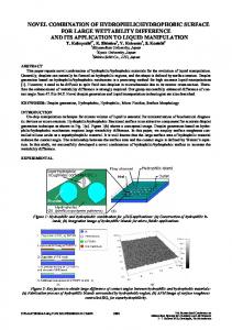
2. EXPERIMENTAL METHODS 2.1. Materials and Characterization. The hydrophilic photocurable resin was a mixture of 99.28 wt % PEGDA (700) (SigmaAldrich, St. Louis, MO, USA), 0.67 wt % photoinitiator Irgacure 819 (Phenylbis(2,4,6-trimethylbenzoyl)phosphine oxide; Sigma-Aldrich, St. Louis, MO, USA), and 0.05 wt % photoabsorber Sudan I (Sigma-Aldrich, St. Louis, MO, USA). The hydrophobic photocurable resin was a mixture of 87.92 wt % PPGDMA (560) (Sigma-Aldrich, St. Louis, MO, USA), 10.99 wt % 2,2′-(ethylenedioxy)diethanethiol (EDDET; Sigma-Aldrich, St. Louis, MO, USA), 0.99 wt % photoinitiator Irgacure 819 and 0.1 wt % photoabsorber Suduan I. After fully cured under UV light, the thermomechanical properties of these two polymers were characterized by using a dynamic mechanical analysis tester (Q800, TA Instruments, New Castle, DE, USA) in a multistrain mode. Samples were first heated to 40 °C and stabilized for 10 min. After that, the temperature was decreased to −50 °C at a rate of 2 °C/min. During this process, a preload of 0.001 N was applied to the sample and the strain was oscillated at a frequency of 1 Hz with a peak amplitude of 0.1%. In order to test the swelling behaviors of PEGDA and PPGDMA, 0.7 mm thick disc samples with a diameter of 20 mm were immersed in water. A digital camera (EOS 7D, Canon Inc, Japan) was used to catch snapshots during the swelling process. The linear swelling ratio was calculated through α = (At/A0)1/2 by analyzing the videos using a MATLAB (MathWorks, Natick, MA, USA) code. Here, A0 is the initial area of the disc, and At is the area after swelling. 2.2. Printing Method. A DLP projector (D912HD, Vivitek USA, City of Industry, CA, USA; modified by B9creations, Rapid City, SD, USA) was utilized to fabricate the hydrophilic/hydrophobic composite structures. In order to create complex three-dimensional (3D) shape changes, the hydrophilic PEGDA rubber should be attached on both sides of the hydrophobic PPGDMA sheet and the mismatch strain will cause the structure to fold toward both sides. One straightforward approach was to create two separate PEGDA patterns first (as shown in Figure 1A). For each PEGDA pattern, a layer of liquid PEGDA resin was confined between two glass slides. The thickness of the liquid was defined by precise plastic spacers. The surface of one glass slide was hydrophilic, and the surface of the other one was hydrophobic. To define the shape of the hydrophilic layer, light pattern was illuminated to the liquid layer from the side with a hydrophilic glass by using the DLP projector (Figure 1A(1)). The thickness of the PEGDA layer was dependent on the incident light intensity and the illumination time.17 By using a grayscale light pattern, continuous variation of PEGDA thickness could be realized. After demolding, the solid PEGDA would stick to the hydrophilic glass (Figure 1A(2)). Then, the two glass slides with two separate PEGDA patterns were assembled to form a new mold, and the hydrophobic liquid resin PPGDMA was injected to fill the space between the PEGDA patterns (as shown in Figure 1A(3)). The final shape of the structure was defined by further illuminating the mixture of the solid PEGDA and the liquid PPGDMA resin with a third light pattern. Shape-shifting could be induced by immersing the final structure in deionized water (Figure 1A(4)). To investigate the time response of the composite structure, bilayer rectangular strips with different thickness compositions of PEGDA and PPGDMA were immersed in water for taking videos. We used Image J19 to obtain the evolution of bending curvature as a function of time. 2.3. Modeling the Bilayer Hydrophilic/Hydrophobic Structure. Mechanical modeling of swelling-induced deformation in hydrogels and elastomers has been an intensive research in the past. Continuum frameworks were proposed to describe the coupling between diffusion and large deformation in polymer hydrogels.3,20 Implemented by finite element method (FEM), continuum coupling theories were utilized to obtain transient behaviors of swelling hydrogels and water-driven devices.21−24 However, because of the complexity in solving the coupling between diffusion and deformation, it is computationally inefficient for complex structures and extreme
Figure 1. (A) Fabrication process of the hydrophilic/hydrophobic composite structures. (1) Two separate PEGDA patterns were cured between glass slides under different light patterns. (2) Cured patterns stick to the hydrophilic glass were demolded from the hydrophobic glass. (3) Assembly of two PEGDA patterns, injection of the PPGDMA liquid resin, and curing of the total structure. (4) Shapeshifting of the composite structure in water. (B) Bending of a bilayer hydrophilic/hydrophobic structure.
geometries.13 For example, if the diffusivity is relatively high or if there exist sharp corners, extremely small time steps and dense meshes should be utilized to ensure convergence. On the other hand, most of the previous analytical solutions for swelling bilayer were restricted to the deformation at equilibrium swelling ratio,25−27 where the time history of the actuation was not considered. Here, our goal was to develop a simple model for the hydrophilic/hydrophobic bilayer, which can capture the transient deformation during swelling. Because the swelling ability of hydrophilic PEGDA is much lower than that of polymer hydrogels (with a volume swelling ratio higher than 3) studied in previous works,5,6,11 it is reasonable to ignore the coupling between diffusion and deformation. Therefore, the diffusion of water is described by the one-dimensional diffusion equation ∂C(x , t ) ∂ 2C(x , t ) =D ∂t ∂x 2
(1)
here, C is the mole concentration (mol L−1) of water, t is the time, x is the coordinate across thickness (the definition of the coordinate system is shown in Figure 1B), and D is the diffusion coefficient of water in PEGDA. When subjected to the boundary conditions,
B
C|x = h = C0
(2A)
∂C ∂x
(2B)
=0 x=0
DOI: 10.1021/acsami.8b02444 ACS Appl. Mater. Interfaces XXXX, XXX, XXX−XXX
Research Article
ACS Applied Materials & Interfaces where C0 is the equilibrium water concentration in PEGDA and h is the thickness of the PEGDA layer, the profile of C can be obtained from eq 1 as28 C(x , t ) = C0 − C0 cos
bonded together and meshed with shell element (element type S3 in ABAQUS). Because of their high modulus and small swelling ratio, the two-type rubbers were modeled as conventional elastic materials. It should be noted that many previous research studies utilized the hyperelastic model to simulate the deformation of hydrogels,31,32 in which the stretch ranges from moderate (∼10%) to large (>50%). In our work, the volume expansion strain of stiff rubber is around 10% and the strain during bending is also relatively small (∼10%). As a result, the linear elastic model is adequate to describe the mechanical behavior during swelling (Figure S1). Young’s moduli of PEGDA and PPGDMA were set to the values in Table 1. The Poisson’s ratio was
∞ n 2 2 ⎫ ⎧ π ∑ (−1) exp⎨− D(2n + 21) π t ⎬ 4 n = 0 2n + 1 4h ⎩ ⎭
(2n + 1)πx 2h
(3)
Equation 3 is also the solution for the free swelling of a PEGDA film with a thickness of 2 h subjected to the symmetrical boundary conditions28 C|x =−h = C|x = h = C0
Table 1. Parameters in the Model
(4)
The swelling stretch (or the linear swelling ratio) of the polymer is given by22
λs = (1 + ΩC)1/3
(5)
where, Ω is the volume of 1 mol of water molecules. In order to describe the free swelling process in Figure 1B, the linear swelling ratio of the disc is approximated through average across thickness λs =
1 2h
h
(6)
Upon equilibrium, the swelling stretch across thickness becomes uniform and the average stretch λs approaches the equilibrium swelling stretch, λse = (1 + ΩC0)1/3. Once λes is obtained from experiments, the equilibrium water concentration C0 can be calculated. Taking eq 3 into eq 6, the unknown parameter D is fitted by comparing experiments and the calculation result. When a layer of PEGDA with a thickness of h and a layer of PPGDMA with a thickness of H are bonded together (Figure 1B), the strain in the PEGDA layer is given by29,30 e1 = εb − ln λs + κx
value
description
2.7 × 10⁻⁵ 4.2 0.18 27 10
water diffusion coefficient (calculated) equilibrium water concentration (calculated) mole volume of water (calculated) Young’s modulus of PEGDA (tested) Young’s modulus of PPGDMA (tested)
set to 0.49 to approximate the incompressible behavior of rubbers. One element at the center of the plate was fixed to imitate the free swelling process. Here, we were only interested in the equilibrium swelling shape of the bilayer plate. Thus, a constant volume expansion was applied to the PEGDA layer. An analogy between swelling and thermal expansion was utilized by applying constant temperature field during the simulation.24 Automatic stabilization was activated to ensure convergence during simulations. A flowchart of the FEM simulation process is found in the Supporting Information (Figure S3).
h
∫−h λs dx = 21h ∫−h (1 + ΩC)1/3 dx
parameters D (mm2 s−1) C0 (mol L−1) Ω (L mol−1) E1 (MPa) E2 (MPa)
3. RESULTS 3.1. Material Characterization. Figure 2A shows the storage modulus and tan δ of the two rubbers as functions of
(7A)
Here εb is the strain of the interface and κ is the curvature of the interface. The strain in the PPGDMA layer is
e 2 = εb + κx
(7B)
During the free deformation of a swelling bilayer, the equilibrium of total external force and total external moment should be satisfied 0
∑F = ∫
−H
∑M = ∫
E 2 e 2 dx +
∫0
0
−H
E 2 e 2x d x +
h
E1e1 dx = 0
∫0
(8A)
h
E1e1x dx = 0
(8B)
Figure 2. (A) Thermomechanical properties of the PEGDA rubber and the PPGDMA rubber. (B) Swelling behaviors of PEGDA and PPGDMA in water.
here, E1 and E2 are Young’s modulus of PEGDA and PPGDMA, respectively. Combining eqs 8A and 8B, the bending curvature at time t is given by
temperature. The rubbery modulus of the hydrophilic PEGDA could be as high as 27 MPa. The glass-transition temperatures were −25 and −10 °C for PEGDA and PPGDMA, respectively. Figure 2B shows the linear swelling ratios of the two elastomers. Results for the PEGDA swelling ratio were used to identify parameters in the model, which are shown in Table 1. 3.2. Actuation of a Bilayer Hydrophilic/Hydrophobic Structure. Bilayer structures by using a responsive layer and a support layer are the most common designs for active devices.33 In the current work, the PEGDA/PPGDMA bilayer samples were fabricated with identical total dimensions of 20 mm × 5 mm × 0.635 mm (length × width × thickness) but different PEGDA layer thicknesses (25, 38, 51, 76, and 102 μm). It should be noted that we only studied the case when the active layer was much thinner than the support layer. If the
κ= 1 (E h2 2 1
h
2
h
− E2H )∫ E1ln λs(x , t )dx − (E1h + E2H )∫ E1ln λs(x , t )x dx 0
1 (E h2 4 1
0
1
− E2H2)2 − 3 (E1h3 + E2H3)(E1h + E2H )
(9) If the swelling of PEGDA reaches equilibrium, the final curvature becomes
κ=
1 E ln λ e[(E1h2 2 1 1 (E h2 − E2H2)2 4 1
− E2H2)h − (E1h + E2H )h2] 1
− 3 (E1h3 + E2H3)(E1h + E2H )
(10)
2.4. Finite Element Simulation of the Bilayer Hydrophilic/ Hydrophobic Plate. We implemented FEM simulations in the commercial software ABAQUS (Dassault Systems, Waltham, MA, USA) to investigate the underlying mechanism for the directional bending behavior of the bilayer hydrophilic/hydrophobic plate. Two shells representing the PEGDA layer and the PPGDMA layer were C
DOI: 10.1021/acsami.8b02444 ACS Appl. Mater. Interfaces XXXX, XXX, XXX−XXX
Research Article
ACS Applied Materials & Interfaces
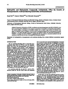
generated by the PEGDA layer is shown as a function of swelling time in Figure 3C (the PEGDA thickness of 51 μm and the total thickness of 0.635 mm). The force is 2 orders of magnitude higher than that created by a conventional hydrogel layer with the identical geometry. Details of the calculation of actuation force can be found in the Supporting Information. Because the bending is controlled by the diffusion of water into the PEGDA layer (if we ignore the coupling between bending deformation and diffusion), it is reasonable to assert that the relative actuation speed, or the rate to reach the maximum bending curvature, should solely depend on the PEGDA layer thickness. This assertion was confirmed in Figure 3D where three types of bilayers with an identical PEGDA thickness of 51 μm but different PPGDMA thicknesses (380, 635, and 1000 μm) were tested. As marked by the black dot line, the time reaches 85% of the final curvatures (actuation time) which were almost identical. Therefore, by adjusting the thickness of PPGDMA, bilayers with same relative actuation speed but distinct levels of deformation could be created. 3.3. Design of the Bilayer Hydrophilic/Hydrophobic Structure. The discussion in section 3.2 does not consider the total thickness. In some applications, the dimension of the actuator is predefined. As shown in Figure 3A,B, if the total thickness is restricted, there is a competition between the actuation time and the final bending curvature. By using the analytical model, we can determine individual layer thicknesses to achieve the desired actuation speed, bending curvature, and overall dimension. Here, we considered two design scenarios. In the first design scenario, we restricted ourselves by using the two base materials described in section 2 and we would like to design a bilayer strip that can deform to a specific curvature within a certain time period, without limiting the total thickness. This can be achieved by adjusting the individual layer thicknesses. The design diagram is shown in Figure 4. As
hydrophilic active layer is too thick, it will take a long time for the system to reach equilibrium swelling, which is undesirable for actuators and therefore was not studied in this paper. After immersed in water, the PEGDA layer swells and expands, driving the structure to bend toward the PPGDMA layer (shown schematically in Figure 1B). Figure 3A shows the
Figure 3. (A) Time response of bilayers with identical total thickness and distinct components (different thicknesses of the PEGDA layer). (B) Deformation and actuation of bilayers with identical total thickness and distinct components (different thicknesses of the PEGDA layer). (C) Actuation force of the bilayer as a function of swelling time (PEGDA thickness 51 μm, total thickness 0.635 mm). (D) Time response of bilayers with the identical thickness of the PEGDA layer.
evolution of bending curvature as a function of swelling time, which is similar to the expansion of a freely swelling disc in Figure 2B. The actuation process was dependent on the dimensions of the individual components as well as of the entire structure. The bilayer with the ultrathin PEGDA layer (e.g., 25 μm) showed the largest curvature at the beginning; it also showed the fastest response and reached the bending curvature of 0.14 mm−1 in ∼25 s. The reason might be explained as follows. Because the thickness was much smaller than the width and the length, it is reasonable to assume that the diffusion of water was a one-dimensional process across the thickness. At the beginning of the swelling, because water molecules only diffused into the top surface of PEGDA, the distributions of water should be identical for different samples. However, because PEGDA rubber was stiffer than PPGDMA rubber, the sample with the thinnest PEGDA layer exhibited the lowest bending stiffness. As a result, this sample was the one with the fastest response. Another feature of a bilayer with the ultrathin PEGDA was the fast speed to reach its final shape. A bilayer with 25 μm PEGDA deformed to its final shape in ∼25 s. This behavior is attributed to the fact that water diffusion was faster to achieve equilibrium in a thin layer. As shown in Figure 3B, the actuation time (time to reach 85% of the final curvature) increased to almost 10 times if the thickness of the PEGDA layer increased by threefold. Comparisons between the experiments and the theoretical calculations are shown in Figure 3A,B. The actuation of the PEGDA/PPGDMA bilayer is well-captured by the simple model. The actuation force
Figure 4. Design diagram for a hydrophilic/hydrophobic bilayer with arbitrary thickness (the contour plot on the right represents the final curvature).
we pointed out previously in Figure 3D, the relative actuation speed is solely dependent on the PEGDA layer. Therefore, to design such a structure, the thickness of PEGDA was found based on the desired actuation time, which is shown on the left side of Figure 4. Then, considering the final curvature, the thickness of PPGDMA was decided from the right by checking the contour color in Figure 4. The red dot in Figure 4 corresponds to a real sample with 38 μm PEGDA in Figure 3A. In the second scenario, the total thickness was constant, whereas the actuation time and the final curvature were also restricted. As a result, one more degree of freedom was needed in the design space. Here, we show the feasibility to adjust D
DOI: 10.1021/acsami.8b02444 ACS Appl. Mater. Interfaces XXXX, XXX, XXX−XXX
Research Article
ACS Applied Materials & Interfaces Young’s modulus of the PPGDMA of the hydrophobic layer. This choice was assumed to have no impact on the actuation of PEGDA. It should be noted, as discussed in section 2, a small amount of EDDET thiol was added to the PPGDMA resin. The purpose was to reduce the modulus and the glasstransition temperature of cross-linked PPGDMA. On the basis of the same idea, other types of monomers could be mixed with PPGDMA to adjust the rubbery modulus.34,35 Here, we show a design diagram by using the analytical model. The total thickness of the bilayer was set to 0.635 mm. Following the same process in Figure 4, the thickness of PEGDA and the modulus of PPGDMA could be found from the diagram. The thickness of PPGDMA was dependent on the thickness of PEGDA. As shown in Figure 5, the final bending curvature can be significantly increased by reducing the modulus of the PPGDMA layer.
Figure 6. 3D hydrophilic/hydrophobic composite shape-shifting structures. (A) Wavy ring. (B) Helix ribbon. (C) Curved leaf. (D) Miura-ori origami. (Scale bar: 10 mm; three sets of grayscale images to create the structures are listed on the top of each structure.)
Figure 6D. The Miura-ori-type shape-shifting was realized by PEGDA/PPGDMA composite hinges between PPGDMA panels. Because of the discrepancy in stiffness along the long edge and the short edge as well as the geometrical constraints of flat panels,13 the composite hinge bend along the short edge, as it is easier to bend in this direction. This will move adjacent panels together. Inspired by results in Figure 3A,B, the hydrophilic/ hydrophobic composite structure was also utilized to create sequential shape-shifting devices.36 The actuation time could be controlled by regulating the thickness of the PEGDA layer within a flat sheet with uniform total thickness. Two examples of sequential water-responsive structures are shown in Figure 7. Similar to Figure 6C, grayscale images were used to realize the variation of PEGDA thickness during a single-step illumination. Figure 7A shows a strip that deformed to “S” shape after swelling in water. The three grayscale images listed on the top of Figure 7A were used to create the strip (also see Movie S1 in Web Enhanced Objects). Here, the PEGDA layer consisted of two parts: one was thicker and was formed by using the bright pattern on the left; another was thinner and was formed by using the dark pattern in the middle. Finally, the bright pattern on the right was used to create the PPGDMA layer. After immersed in water, the side with thinner PEGDA (or the left part) of the strip deformed to its final shape within 1 min, whereas the side with thicker PEGDA (or the right part) continued to bend, reaching its final bending state in 3 min. Because the friction between the right end and the substrate was higher than that between the left bottom and the substrate, the subsequent deformation of the right part drove the strip to move toward the right. Figure 7B shows a sequential waterresponsive flower (also see Movie S2 in Web Enhanced Objects). A grayscale image with different intensities for two sets of petals was illuminated to create a PEGDA layer with a staggered variation of thickness. After immersed in water, one
Figure 5. Design diagram for a hydrophilic/hydrophobic bilayer with definite thickness (the contour plot on the right represents the final curvature).
3.4. Water-Responsive Shape-Shifting Structures. DLP is an effective technology to pattern smart polymer structures from photocurable polymer resins.17,18 Instead of utilizing complex photomasks, polymer structures are created by singlestep or multistep illumination of predefined grayscale images. In order to fabricate hydrophilic/hydrophobic composite shape-shifting structures, three sets of grayscale images are needed to define the hydrophilic water-responsive layers and the hydrophobic support layer. As introduced in the Experimental Methods section, the first two grayscale images (or one single image, if PEGDA is only at one side) listed on the top of each structure defined the PEGDA layer, whereas the third image defined the PPGDMA layer. After the DLP processing, flat polymer sheets were immersed in water and their final shapes at equilibrium swelling are presented in Figure 6. Figure 6A shows a wavy ring results from nonuniform bending and subsequent out-of-plane buckling of a ring plate. Helix ribbon could also be created by introducing PEGDA fibers onto one side of a PPGDMA sheet (Figure 6B). An advantage of using DLP is the convenience to introduce gradient of light intensity into the light patterns. In Figure 6C, we show a leaf with a nonuniform curvature. A gradient light pattern along the long axis was used to create the second PEGDA layer. The high intensity near the bottom of the leaf corresponds to a thick layer of PEGDA, whereas the low intensity near the top corresponds to a thin layer. Similar to results in Figure 3, the final curvature near the bottom was much higher than that near the top. We also show the feasibility of our method to create much more complex 3D origami structures. A traditional Miura-ori origami shape is shown in E
DOI: 10.1021/acsami.8b02444 ACS Appl. Mater. Interfaces XXXX, XXX, XXX−XXX
Research Article
ACS Applied Materials & Interfaces
Figure 7. (A) Sequential water-responsive “S” strip. (B) Sequential water-responsive flower. (Scale bar: 10 mm; three sets of grayscale images to create the structures are listed on the top of each structure; snapshots of the actuation are presented on the left of each structure.)
Figure 8. Experiments and FEM simulations of free-swelling polygon plates. (A) Rectangle. (B) Pentagon. (C) Hexagon. (D) Heptagon. (E) Octagon. (Scale bar: 5 mm. The bending axis is marked by the dashed line.)
set of petals soon reached the equilibrium bending, which corresponded to a small curvature. The other set continued to bend and finally deformed to much-curved shapes. The final shape of each structure after swelling is shown on the right side in Figure 7. 3.5. Directional Bending of a Free-Swelling Bilayer. Water-responsive structures shown in section 3.4 involved nonuniform PEGDA/PPGDMA composition inside a flat sheet, and the deformation of such structure was restricted by adjacent geometries. In this section, we investigated a different type of bilayers with a uniform PEGDA/PPGDMA composition. A layer of flat PEGDA with uniform thickness was bonded to a layer of flat PPGDMA, whereas the in-plane shape of the bilayer could be designed arbitrarily. An interesting question of a shape-shifting bilayer with an arbitrary shape is what the preferred direction is in which it will bend. Upon activation, a rectangular bilayer bends with respect to the short axis.37 This preference was attributed to the minimization of strain energy from the “edge effect”. As for bilayers with complex shapes, theoretical predictions and simulations38,39 were conflicting in the past. Here, we show the swelling-induced shape-shifting of some polygon bilayer plates. Experimental results of the final swelling shapes are shown in Figure 8. If the mismatch strain of the bilayer plate is small, two principle curvatures should be equal and the plate deforms to a spherical surface. Further increasing the mismatch strain, bifurcation occurs to minimize the total elastic strain energy as well as regions of double curvature and the plate deforms to a cylindrical surface.40 For the swelling rubbery bilayer in this paper, the latter can be applied and the final shape was similar to bend the plate with respect to one single axis. As shown in Figure 8A, identical to previous studies,37 a rectangular bilayer plate bent with respect to its short axis (Figure 8A). For other types of polygons, we conducted several experiments and except some special cases, almost all of them turned to bend with respect to a specific axis.
The preferred bending shapes are listed on the top of each subplot in Figure 8. Simulated shapes of the polygons are listed at the bottom of each subplot in Figure 8, and the directional bending behavior could be well-captured. Because of symmetry, a polygon should bend with respect to its symmetrical axis or an axis perpendicular to its symmetrical axis. In order to find out the reason for directional bending, we further simulated the case by imposing extra constraints to demand the plate bend with respect to other possible axes. The profiles of elastic strain energy density after swelling were extracted and plotted on the reference configuration in Figure 9. Previously, Alben et al. pointed out that the directional bending of a rectangular plate is attributed to the “edge effect”.37 Upon swelling, the bilayer plate deforms to minimize its total strain energy. Local deformation (e.g., curling) results in a reduction of the local strain energy density. An examination on the distribution of strain energy density explains why the plate deforms to a certain nonuniform shape. Although the rectangular plate finally deforms to nearly a cylindrical surface because the constraints near edges are weaker than that at the center, edges perpendicular to the bending axis show slightly higher curvatures.41 As a result, the strain energies at those curved edges are further reduced. For a rectangular plate, only two out of four edges can exhibit the “edge effect” and the other two edges parallel to the bending axis do not have the effect. The plate bent with respect to the short axis (the axis marked by dashed line in Figure 9A top) in which those two longer edges showing the “edge effect” (edges marked by small crosses in Figure 9A top) can reduce more energy. The “edge effect” only occurred in a small region near the boundary. As shown in Figure 9A, compared with bending with respect to the long axis (Figure 9A bottom), the total energy of the actual deformation was reduced by 0.66%. As Albens et al.37 pointed out, this small reduction in strain energy was enough to induce the directional bending behavior. Next, we show that the same analysis can be F
DOI: 10.1021/acsami.8b02444 ACS Appl. Mater. Interfaces XXXX, XXX, XXX−XXX
Research Article
ACS Applied Materials & Interfaces
structures. Sequential water response was also realized by controlling the actuation speed at different regions. On the basis of the hydrophilic/hydrophobic composite system, we also investigated the directional bending behavior of bilayer plates with arbitrary shapes. Inspired by experiments and simulations, we found a polygon bilayer plate bends with respect to a specific axis to minimize its total elastic strain energy.
■
ASSOCIATED CONTENT
S Supporting Information *
The Supporting Information is available free of charge on the ACS Publications website at DOI: 10.1021/acsami.8b02444. Material parameter identification; actuation force of the PEGDA rubber; supplementary information for the finite element simulation (PDF) Sequential water responsive “S” strip (MPG) Sequential water responsive flower (MPG)
■
AUTHOR INFORMATION
Corresponding Authors
*E-mail:
[email protected] (H.J.Q.). *E-mail:
[email protected],
[email protected] (D.F.).
Figure 9. Strain energy densities of free-swelling polygon plates. (A) Rectangle. (B) Pentagon. (C) Hexagon. (D) Heptagon. (E) Octagon. (Top: actual deformation, bottom: comparison group; the bending axis is marked by dashed line, and boundaries showing the edge effect are marked by small crosses. The reductions of strain energy are marked on the top of each subplot.)
ORCID
H. Jerry Qi: 0000-0002-3212-5284 Notes
The authors declare no competing financial interest.
■
ACKNOWLEDGMENTS We gratefully acknowledge the support of an AFOSR grant (FA9550-16-1-0169; Dr. B.-L. “Les” Lee, Program Manager). We also acknowledge the support of the NSF awards (CMMI1462894 and CMMI-1462895). A gift fund from HP, Inc is also greatly appreciated. Z.Z. and D.F. acknowledge a support from National Natural Science Foundation of China (11521202) and a support from National Materials Genome Project of China (2016YFB0700600). Z.Z. acknowledges a support from China Scholarship Council (no. 201506010219).
applied to other polygon plates. Even though there might not be an edge that is perfectly perpendicular to the bending axis or parallel to the bending axis anymore, we could still identify two groups of edges. Some of them showed the ‘edge effect’ with apparent reduction in strain energy (edges with the “edge effect” are marked by small crosses in Figure 9); the others showed no “edge effect”. For a pentagon plate, if it bends with respect to the axis perpendicular to its symmetrical axis, only two out of five edges exhibit the “edge effect” (Figure 9B bottom). If it bends with respect to its symmetrical axis, three out of five edges would exhibit the “edge effect” (Figure 9B top) and the total energy is minimized. Similar phenomenon holds for other polygons, and we can conclude, a free swelling bilayer polygon turns to bend with respect to the axis in which a maximum number of edges exhibiting the “edge effect” could be realized.
■
REFERENCES
(1) Reyssat, E.; Mahadevan, L. Hygromorphs: From Pine Cones to Biomimetic Bilayers. J. R. Soc., Interface 2009, 6, 951−957. (2) Meng, H.; Hu, J. A Brief Review of Stimulus-active Polymers Responsive to Thermal, Light, Magnetic, Electric, and Water/Solvent Stimuli. J. Intell. Mater. Syst. Struct. 2010, 21, 859−885. (3) Hong, W.; Zhao, X.; Zhou, J.; Suo, Z. A Theory of Coupled Diffusion and Large Deformation in Polymeric Gels. J. Mech. Phys. Solids 2008, 56, 1779−1793. (4) Jeong, K.-U.; Jang, J.-H.; Kim, D.-Y.; Nah, C.; Lee, J. H.; Lee, M.H.; Sun, H.-J.; Wang, C.-L.; Cheng, S. Z. D.; Thomas, E. L. Threedimensional Actuators Transformed From the Programmed Twodimensional Structures via Bending, Twisting and Folding Mechanisms. J. Mater. Chem. 2011, 21, 6824−6830. (5) Lee, H.; Xia, C.; Fang, N. X. First Jump of Microgel: Actuation Speed Enhancement by Elastic Instability. Soft Matter 2010, 6, 4342− 4345. (6) Jamal, M.; Kadam, S. S.; Xiao, R.; Jivan, F.; Onn, T.-M.; Fernandes, R.; Nguyen, T. D.; Gracias, D. H. Bio-Origami Hydrogel Scaffolds Composed of Photocrosslinked PEG Bilayers. Adv. Healthcare Mater. 2013, 2, 1142−1150. (7) Randall, C. L.; Gultepe, E.; Gracias, D. H. Self-folding Devices and Materials for Biomedical Applications. Trends Biotechnol. 2012, 30, 138−146.
4. CONCLUSIONS We proposed a novel type of hydrophilic/hydrophobic composite water-responsive structure. The composite constitutes a PEGDA hydrophilic layer that expands upon swelling in water and a PPGDMA hydrophobic layer that acts as a soft support material. Compared with conventional hydrogel waterresponsive designs, our structure has higher actuation speed and actuation force without introducing heating or electrical stimulations. The time response of the hydrophilic/hydrophobic composite was investigated experimentally and theoretically. Structures with desirable actuation behavior could be designed by manipulating the composition of the two materials. Another advantage of our material system is the feasibility to pattern complex shapes by using the DLP method. Several water-responsive 3D shape-shifting structures were presented, including classical origamis and biomimetic G
DOI: 10.1021/acsami.8b02444 ACS Appl. Mater. Interfaces XXXX, XXX, XXX−XXX
Research Article
ACS Applied Materials & Interfaces (8) Fernandes, R.; Gracias, D. H. Self-folding Polymeric Containers for Encapsulation and Delivery of Drugs. Adv. Drug Delivery Rev. 2012, 64, 1579−1589. (9) Forterre, Y.; Dumais, J. Generating Helices in Nature. Science 2011, 333, 1715−1716. (10) Gladman, A. S.; Matsumoto, E. A.; Nuzzo, R. G.; Mahadevan, L.; Lewis, J. A. Biomimetic 4D Printing. Nat. Mater. 2016, 15, 413. (11) Na, J.-H.; Evans, A. A.; Bae, J.; Chiappelli, M. C.; Santangelo, C. D.; Lang, R. J.; Hull, T. C.; Hayward, R. C. Programming Reversibly Self-Folding Origami with Micropatterned Photo-Crosslinkable Polymer Trilayers. Adv. Mater. 2015, 27, 79−85. (12) Zhao, Z.; Wu, J.; Mu, X.; Chen, H.; Qi, H. J.; Fang, D. Desolvation Induced Origami of Photocurable Polymers by Digit Light Processing. Macromol. Rapid Commun. 2016, 38, 1600625. (13) Mao, Y.; Ding, Z.; Yuan, C.; Ai, S.; Isakov, M.; Wu, J.; Wang, T.; Dunn, M. L.; Qi, H. J. 3D Printed Reversible Shape Changing Components with Stimuli Responsive Materials. Sci. Rep. 2016, 6, 24761. (14) Yuk, H.; Lin, S.; Ma, C.; Takaffoli, M.; Fang, N. X.; Zhao, X. Hydraulic Hydrogel Actuators and Robots Optically and Sonically Camouflaged in Water. Nat. Commun. 2017, 8, 14230. (15) Lv, C.; Xia, H.; Shi, Q.; Wang, G.; Wang, Y.-S.; Chen, Q.-D.; Zhang, Y.-L.; Liu, L.-Q.; Sun, H.-B. Sensitively Humidity-Driven Actuator Based on Photopolymerizable PEG-DA Films. Adv. Mater. Interfaces 2017, 4, 1601002. (16) Stoychev, G.; Guiducci, L.; Turcaud, S.; Dunlop, J. W. C.; Ionov, L. Hole-Programmed Superfast Multistep Folding of Hydrogel Bilayers. Adv. Funct. Mater. 2016, 26, 7733−7739. (17) Zhao, Z.; Wu, J.; Mu, X.; Chen, H.; Qi, H. J.; Fang, D. Origami by Frontal Photopolymerization. Sci. Adv. 2017, 3, No. e1602326. (18) Huang, L.; Jiang, R.; Wu, J.; Song, J.; Bai, H.; Li, B.; Zhao, Q.; Xie, T. Ultrafast Digital Printing toward 4D Shape Changing Materials. Adv. Mater. 2017, 29, 1605390. (19) Schneider, C. A.; Rasband, W. S.; Eliceiri, K. W. NIH Image to ImageJ: 25 Years of Image Analysis. Nat. Methods 2012, 9, 671−675. (20) Chester, S. A.; Anand, L. A Coupled Theory of Fluid Permeation and Large Deformations for Elastomeric Materials. J. Mech. Phys. Solids 2010, 58, 1879−1906. (21) An, N.; Li, M.; Zhou, J. Predicting Origami-inspired Programmable Self-folding of Hydrogel Trilayers. Smart Mater. Struct. 2016, 25, 11LT02. (22) Chester, S. A.; Di Leo, C. V.; Anand, L. A finite Element Implementation of a Coupled Diffusion-deformation Theory for Elastomeric Gels. Int. J. Solids Struct. 2015, 52, 1−18. (23) Guo, W.; Li, M.; Zhou, J. Modeling Programmable Deformation of Self-folding All-polymer Structures with Temperature-sensitive Hydrogels. Smart Mater. Struct. 2013, 22, 115028. (24) Duan, Z.; Zhang, J.; An, Y.; Jiang, H. Simulation of the Transient Behavior of Gels Based on an Analogy Between Diffusion and Heat Transfer. J. Appl. Mech. 2013, 80, 041017. (25) Nardinocchi, P.; Puntel, E. Finite Bending Solutions for Layered Gel Beams. Int. J. Solids Struct. 2016, 90, 228−235. (26) Drozdov, A. D.; Christiansen, J. D. Swelling-induced Bending of Bilayer Gel Beams. Compos. Struct. 2016, 153, 961−971. (27) Abdolahi, J.; Baghani, M.; Arbabi, N.; Mazaheri, H. Analytical and Numerical Analysis of Swelling-induced Large Bending of Thermally-activated Hydrogel Bilayers. Int. J. Solids Struct. 2016, 99, 1−11. (28) Crank, J. The Mathematics of Diffusion; Oxford university press, 1979. (29) Wu, J.; Yuan, C.; Ding, Z.; Isakov, M.; Mao, Y.; Wang, T.; Dunn, M. L.; Qi, H. J. Multi-shape Active Composites by 3D Printing of Digital Shape Memory Polymers. Sci. Rep. 2016, 6, 24224. (30) Ge, Q.; Dunn, C. K.; Qi, H. J.; Dunn, M. L. Active Origami by 4D Printing. Smart Mater. Struct. 2014, 23, 094007. (31) Westbrook, K. K.; Qi, H. J. Actuator designs using environmentally responsive hydrogels. J. Intell. Mater. Syst. Struct. 2008, 19, 597−607.
(32) Boyce, M. C.; Arruda, E. M. Swelling and mechanical stretching of elastomeric materials. Math. Mech. Solid 2001, 6, 641−659. (33) Liu, Y.; Genzer, J.; Dickey, M. D. “2D or not 2D”: Shapeprogramming Polymer Sheets. Prog. Polym. Sci. 2016, 52, 79−106. (34) Xi, W.; Scott, T. F.; Kloxin, C. J.; Bowman, C. N. Click Chemistry in Materials Science. Adv. Funct. Mater. 2014, 24, 2572− 2590. (35) Safranski, D. L.; Gall, K. Effect of Chemical Structure and Crosslinking Density on the Thermo-mechanical Properties and Toughness of (Meth)acrylate Shape Memory Polymer Networks. Polymer 2008, 49, 4446−4455. (36) Mao, Y.; Yu, K.; Isakov, M. S.; Wu, J.; Dunn, M.; Qi, H. J. Sequential Self-Folding Structures by 3D Printed Digital Shape Memory Polymers. Sci. Rep. 2015, 5, 13616. (37) Alben, S.; Balakrisnan, B.; Smela, E. Edge Effects Determine the Direction of Bilayer Bending. Nano Lett. 2011, 11, 2280−2285. (38) Pezzulla, M.; Smith, G. P.; Nardinocchi, P.; Holmes, D. P. Geometry and Mechanics of Thin Growing Bilayers. Soft Matter 2016, 12, 4435−4442. (39) Alben, S. Bending of Bilayers with General Initial Shapes. Adv. Comput. Math. 2015, 41, 1−22. (40) Freund, L. B. Substrate Curvature due to Thin Film Mismatch Strain in the Nonlinear Deformation Range. J. Mech. Phys. Solids 2000, 48, 1159−1174. (41) Fung, Y. C.; Wittrick, W. H. A Boundary Layer Phenomenon in the Large Deflexion of Thin Plates. Q. J. Mech. Appl. Math. 1955, 8, 191−210.
H
DOI: 10.1021/acsami.8b02444 ACS Appl. Mater. Interfaces XXXX, XXX, XXX−XXX