HYDRO+PNEU: A QUASI REALTIME HYDRAULIC AND PNEUMATIC SYSTEM SIMULATION PACKAGE Tony Wong, Pascal Bigras, Daniel Cervera École de technologie supérieure, Université du Québec, 1100 rue Notre Dame Ouest, Montréal (Québec) Canada H3C 1K3 email:
[email protected]
ABSTRACT Hydraulic and pneumatic systems are highly nonlinear and difficult to analyze. This paper presents a quasi real-time simulator designed for efficient numerical simulation of hydraulic and pneumatic systems. This simulator uses a bond-graph theoretic approach for system equation formulation. A highly optimized and stabilized iterative integrator ensures accurate numerical solution of the system equations. Coupled to the integrator’s output is a graphical animation subsystem. The latter is responsible for rendering movable components on screen at every simulation time-step. Thus, creating the illusion of continuous movement. An important characteristic of this simulator is its ability to permit in-simulation manipulation that allows user to interact with circuit components while a simulation run is in progress.
1. INTRODUCTION Hydraulic and pneumatic systems are highly nonlinear. These systems exhibit nonlinear behavior because of restricted flows, finite cylinder length and non-negligible static and dynamic frictions. Pneumatic system nonlinearity is even stronger because of air compressibility. Since no single law exists which describes the resistance of passages to flow, simple design procedures are difficult to obtain due to the analytical complexity involved. Numerical simulations provide a mean to bypass these analytical difficulties. Simulation packages such as NASA’s FAST [1] for transient fluid flow studies and Boeing’s EASY5 [2] for general computational fluid dynamic analysis are suitable for large-scale design problems and fine-grained analysis. Both packages require high-end computers and in-depth knowledge of the engineering discipline. Small-to-medium scale system analysis packages such as MathWorks’ Hydraulic blockset [3] and PNEUMA [4] do not provide visual feedback which could enhance the understanding of the underlying physical phenomena. Also, most simulation packages do not permit explicit hydraulic and pneumatic coupling. Many practical system assemblies require both hydraulic and pneumatic components operating concurrently. It should be interesting to study their interplay without performing complicated conversions and transformations. Our goal is to fulfill the need for a fully adjustable small-to-medium scale simulation package comprising the following characteristics: • • • • • • •
Direct coupling between hydraulic and pneumatic components. Fast and accurate quasi real-time iterative numerical solver for nonlinear differential equations. Continuous and step-by-step simulation modes. Visual feedback using graphical animation synchronized with solver outputs. Arbitrary connection of measurement point (instrumentation) for data collection. In-simulation interactivity between user and circuit components. Graphical editor for easy and intuitive system construction.
2. SIMULATION PACKAGE DESIGN In order to obtain the above mentioned desirable characteristics. We need to employ a systematic and efficient approach for the design and implementation of the simulation package. By modeling all hydraulic, pneumatic and mechanical components as multi-port devices, one can apply the bond-graph theoretic approach for circuit topological recognition. The bond-graph approach is a general technique that results in system equation formulation. It is well suited to the problem of hydraulic, pneumatic and general mechanical systems because of its so-called causality analysis capability [5].
602
2.1 System formulation In our design approach, all components are modeled as multi-port devices. There are two variables associated with each device port. They represent the effort-quantity (pressure, force, etc.) and the flow-quantity (flow, speed, etc.) of the device. However device port’s directional information is not known à priori. That is, input-output relationship of the device ports is dependent on the circuit’s topology. By using bond-graph’s causality analysis method, one can determine input-output relationship of every connected port on-line [5].
Port 1 Port 2 Port n
〈e 1, f 1〉 〈e 2, f 2〉
Hydraulic / pneumatic component
〈e n, f n〉
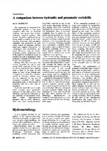
Figure 1 Multi-port device modeling hydraulic and pneumatic components. In a typical system circuit, each component is connected to other components by its ports as shown in figure 1. The couple 〈ei, fi〉 represents the effort and flow variables of port i. There will be a total of N ports in the system circuit. The sets E = {ei | 1 ≤ i ≤ N} and F = {fi | 1 ≤ i ≤ N} are then partitioned into input and output subsets. As mentioned earlier, each variable’s directional information is a function of the component’s causality. Thus, there exists for each component port two possible causalities. This amounts to 2n possible configurations for an n-port component. By applying the causality analysis this can be solved in polynomial time. For each causality, the numerical model of the ith component is a nonlinear ODE system of form x& i = h i (x i ) + b i (x i , u i ) , y i = g i (x i ) + d i (x i , u i )
(1)
where xi is the state vector, yi is the outputs vector and ui is the inputs of the ith component. The system model comprising all circuit components is x& = H (x) + B (x, u) y = G ( x ) + D( x , u )
,
(2)
where x is the state vector, y is the outputs vector and u is the inputs vector of all circuit components. Finally, the input-output coupling between circuit components can be modeled as u = Cy .
(3)
Finally, the global model of all interconnected component results from the substitution of (3) in (2) is x& = H (x) + B(x, Cy ),
(4a)
y = G (x) + D(x, Cy ).
(4b)
We can consider the system equations as an assembly of two coupled subsystems: one depicting the slow-varying part and the other depicting the fast-varying part of the system. In physical terms, the slow-varying part represents the mechanical interactions and the elasticity of the pneumatic fluid. Using similar reasoning, the fast-varying part represents the elasticity of the hydraulic fluid. By application of the singular perturbation theory to our global model, it is possible to transform the set of nonlinear differential equations of the fast-varying part into a set of nonlinear algebraic equations [6]. This result greatly facilitates the construction of the numerical solver. An optimized and stabilized adaptive integrator, an integral part of the numerical solver, is used to ensure the accuracy of the solution at each time-step. Note that the global model includes a static part (4b) and a dynamic part (4a). At each simulation pass, we solve the static part first. The
603
integrator using adaptive time-steps then solves the dynamic part of the system. However, because the latter is iterative in nature, it is not possible to guarantee hard real-time performance. There is a logical interface between the integrator output and the graphical animation subsystem. The latter subsystem is responsible for updating color changes and the redraw of moving parts on behalf of the circuit components (See section 3 for the rationale behind the use of color). The graphical animation subsystem also collaborates closely with circuit components to allow user to perform in-simulation manipulations. An in-simulation manipulation means user can change or modify a component’s state while a simulation run is in progress. Thus, user can stop or start motors, select different distributor chambers, modify cylinder’s longitudinal position, etc. In order to allow in-simulation manipulations, the numerical solver must establish a so-called mechanical chain to determine the effect of changes on other circuit components. This involves the recalculation of system variables and a nontrivial graph traversal to propagate these new values to all connected components. It is worth noting that instrumentation (i.e. adding measurement points to the system) does not increase system complexity. Since instrumentation merely associates a set of system variables to the set of output variables. There is no extra overhead in processing instrumentation measurement points. Finally, instrumentation is preprocessed in the causality analysis phase so that no negative impact can affect the overall simulation time.
3. SIMULATION PACKAGE A small-to-medium scale simulation package has been developed at École de technologie supérieure. This simulation package, called Hydro+Pneu, has been in continuous development since 1996. It enables the user to design hydraulic and pneumatic circuits and to obtain both quantitative and qualitative results rapidly and accurately. The hydro+Pneu simulator is the product of software engineering [7] employing object-oriented approach [8, 9, 10] and advanced system modeling techniques [6]. In Hydro+Pneu, several component palettes are available from the user interface. Below is a short list of theses component palettes. The process of design, simulation and analysis is a sequence of simple steps. These steps and their purposes are given below. q
q
q q
q
Component selection and interconnection. Hydraulic, pneumatic and mechanical components are selected from the component palettes. Using hydraulic and/or pneumatic links and connecting them to component ports, one can create component interconnections to form circuits. Component parameter setting. Each circuit component contains a numerical model whose parameters are fully adjustable from the user interface. User can accept default values or specify fine-tuned values from manufacturer’s data sheets. Instrumentation. Output measurement is the process of collecting data from circuit’s output variables. Various meters and cartesian graphs are available to perform instrumentation. Simulation mode selection. Numerical simulation is performed in either continuous mode or step-by-step mode. In continuous mode, system equations solution and graphical animation updates are continuously executed in a quasi real-time manner. In step-by-step mode, the user is responsible for time-step increment (by depressing a key or a click of the mouse). Post-simulation analysis. Data collected by the grapher object are persistent until the next simulation run. The grapher object can also perform formatted storage operations. This enables extensive post-simulation analysis using appropriate data analysis tools such as Matlab or MatrixX.
Hydro+Pneu uses a color-coded scheme to represent state changes in transient regime and transient-to-steady state transitions. Usually, mechanical displacements (linear translations and rotational movement) can be expressed easily by graphical animations. However, dynamic entities such as pressure differential, flow resistance and temperature variations are much more difficult to express. A color-coded scheme is suitable to represent these dynamic variables. In this scheme a set of colors is mapped to a range of variable values. While a simulation is in progress, the user can notice component internal changes by observing its color variations. For a more quantitative evaluation, the user can also connect measurement components to the circuit. These measurement components display numerical data at each time-step.
604
Table 2 Summary of component palettes. Power train Electric motors, gaz engines, hydraulic and pneumatic pumps, variable displacement pumps, compressor groups. Cylinders Single and double acting cylinders, double rod cylinders, plunger cylinders. Accumulators and controls Weight accumulators, gas accumulators, pressure compensated flow controls, flow controls with check valve. Mechanical components Mass, mass with pulley, slides, hoists, flywheels, disc brakes, speed reducers.
Valves Pressure valves, pilot operated pressure valves, sequence valves with check valve, differential pressure reducing valves. Distributors Directional valves (normally opened), directional valves (normally closed). Peripheral components Tanks, filters with by-pass values, coolers, heaters, atmospheric exhausts. Measurements Pressure gauge, flowmeter, wattmeter, volume meter, thermometer, calibrated reservoir, chronometer, grapher.
3.1 Simulation process Figure 1 shows a typical hydraulic two-speed circuit. This circuit provides differential forward and backward cylinder speeds. The user can control forward or backward motion by activating the distributor chambers.
Figure 1 Typical two-speed hydraulic system with instrumentation and grapher output.
605
Also in figure 1 is a grapher object which shows the cylinder position versus simulation time-steps. To further enhance user-software interactivity, Hydro+Pneu permits in-simulation component manipulations. For example, user can reposition a cylinder’s piston by dragging its shaft without stopping the simulator. It is an important feature since it allows user to experiment with different component settings on-line. The simulator allows hydraulic and pneumatic systems coupling at mechanical contact points. This capability permits the study of different system dynamics and their interplay. In figure 2, the single mechanical contact point is the interface between the pneumatic and hydraulic cylinders. This hybrid circuit shows an interesting application where a pneumatic cylinder, driven by its compressor group, is the prime moving force.
Figure 2 Typical hybrid hydraulic-pneumatic system.
Figure 3 Double acting cylinder’s numerical model parameters and its displacement curve during simulation run.
606
The hydraulic cylinder, which is coupled to the pneumatic one, acts as a retaining force on behalf of the load. Note that this hybrid configuration permits different retaining force for forward and backward cylinder motions since there is two flow controls installed to the hydraulic cylinder. Again, the user can control forward or backward motion by activating the distributor chambers. Every hydraulic, pneumatic and mechanical component possesses a numerical model that is fully adjustable. Figure 3 shows a typical component dialog box for parameter input. In most cases, non-ideal component characteristics are possible. For example, figure 3 depicts an input dialog box for a double acting cylinder. The user can select from several joint leak degrees (negligible, low, medium and high) to obtain non-ideal characteristics caused by aging and wears of the component.
4. FUTURE WORKS The current simulator capabilities are limited to hydraulic, pneumatic and hybrid circuits. There is a need to include models of electrical devices such as AC/DC sources, toggle switches, relays, multi-way contacts and timers. Also of great interest in engineering applications is the design of servomechanism. Their incorporation in Hydro+Pneu would certainly accelerate development of control system geared specifically for hydraulic and pneumatic circuits.
5. CONCLUSION This paper presented a quasi real-time simulator designed for efficient numerical simulation of hydraulic and pneumatic systems. This simulator is suitable for small-to-medium scale circuits analysis and uses a bond-graph theoretic approach for system equation formulation. An optimized and stabilized adaptive integrator, an integral part of the numerical solver, is used to ensure the accuracy of the solution at each time-step. The logical interface between the integrator output and the graphical animation subsystem is also discussed. The graphical animation subsystem is responsible for updating color changes and the redrawing of moving parts on behalf of circuit components. The end result is the ability to create the illusion of continuous movement. Finally an important characteristic of this simulator is its ability to permit in-simulation manipulation which allows user to interact with circuit components while a simulation run is in progress.
6. REFERENCES [1] [2] [3] [4] [5] [6] [7] [8] [9] [10]
http://www.nas.nasa.gov/Software/FAST/ http://www.boeing.com/easy5/ http://www.mathworks.com/products/connections/product_main.shtml?prod_id=212/ http://www.mathworks.com/products/connections/product_main.shtml?prod_id=169/ D.C. Karnopp, D. L. Margolis, R.C. Rosenberg, System Dynamics: A unified Approach, John Wiley & Sons, New York, 1990. H.K. Khalil, Nonlinear Systems, Macmillan, New York, 1992. Ian Sommerville , Software Engineering, 6th ed. Addison-Wesley, 2001. J. Rumbaugh, OMT modeling et object-oriented design, Prentice-Hall, 1995. B. Selic, A Generic Framework for Modeling Resources with UML, IEEE Computer, June, pp. 64-69, 2000. P.B. Kruchten, The 4+1 View Model of architecture, IEEE Software, vol. 12, Issue 6, pp. 42 –50, 1995.
607