Feb 16, 1993 - that a large magnetoresistance appears. Devices are made from the boules by slicing wafers and lapping them to the desired thickness.
J. fhys. 0 Appr. Phys. 26 (1993) 1149-1168. Printed in the UK
I
I
REVIEW ARTICLE
Solid state magnetic field sensors and applications
J Heremans General Motors Research, 30500 Mound Road, Warren, MI 48090, USA Received 16 February 1993 Abstract. This review discusses the propetties d magnetic field sensors based on semiconduclors, such as Hall generators and magnetoresislors, and on magnetic metals, such as permalloy and the recently discovered 'giant magnetoresistance' metallic multilayers. Some emphasis is placed on the comparison between sensors made using these different technologies. Applications of magnetic field sensors in magnetic recording technology and in pasifion sensing will be discussed briefly. Typically a sensor has to detect the difference between a high and a low value of field,around an average, which is of the order of Tin recording applications. but can exceed 0.1 T in position sensors. Hall sensors, magnetoresistors, magnetotransistors, magnetodiodes and carrier-domain magnelometers made from group I V and Ill-V compound semiconductors are described first. Semiconductor magnetoresistors, typically made from InSb, are the solid state devices with the largest sensitivity at Fields exceeding 0.1 T. Recently, lnSb and lnAs films have been grown on insulating InP, GaAs and Si substrates by MBE or NOIICO. Amplifying and signal processing electronics can now be integrated into the substrate onto which the sensor is grown. Magnetoresistors that use an almast two-dimensionallayer of high-mobility electrons show much improved sensitivitiesand operating temperature ranges. Magnetoresistancein magnetic metal films is also used in sensors: permalloy devices are very sensitive in the lower field range. Giant magnetoresistances were discovered in superlattices with alternating layers of magnetic and non-magnetic metals. and the prospective applications of this effect are discussed.
1. introduction
Magnetometers are used in a large number of practical applications. Most important among these are recording heads for magnetic storage devices, magnetic memory elements, and magnetic position and speed sensors. The latter devices use a permanent magnet and a magnetometer to transform a mechanical movement into an electrical signal, and supplant the potentiometer in applications where wear resistance is critical. Magnetic position sensors are preferable over optical sensing techniques in unprotected environments, in which the optics may become coated with contaminants. Magnetic position sensors are now proliferating along with microprocessors in cars and aeroplanes. There are many more magnetometer systems used to measure magnetic fields than can be reviewed here (Foner 1981). First, I briefly list the magnetometer technologies not discussed. Superconductive quantum interference devices (SQIJ~DS) are the most sensitive instruments for measuring magnetic fields. Flux gates (Geyger 1954) exploit the magnetic hysteresis exhibited by ferromagnetic materials. They typically consist 0022-3727/93/081149+20$07.50 Q 1993 IOP Publishing Ltd
of cores of a high-permeability ferromagnet, such as permalloy, equipped with each two coils. The primary coils are driven with an AC voltage so that the core is saturated at each half-cycle of the current. A substantial number of even harmonics of the fundamental frequency f are then generated in each of the secondary coils. The cores of the flux gate are designed so that the application of an external flux to the core changes the saturation point. This changes the amount of output voltage at frequency 2f, which can be detected by an amplifier locked-in at 2 f . Flux gates do exist in thin f i l m form in hybrid circuits (Seitz 1990). Optical magnetometers have been made based on one of three effects. Some use the Zeeman effect in gases such as helium or caesium vapour; these are typically large devices with a high power consumption 1990). Magnetooptical sensors exist that are based on Faraday rotation of polarized light travelling through a magnetic material, for instance a terbium gallium garnet (Lenz 1990). A third optical magnetometer consists of an optical fibre clad with a ferromagnetic Ni layer. Magnetostriction in the cladding changes the effective optical path length, and thus provides for a measurement of an applied 1149
J Heremans
magnetic field (Dandridge etal 1980). There are nuclear precession magnetometers, based on the precession of proton magnetic moments around an applied magnetic field. This type of sensor makes use of hydrocarbon fluids or He3, and the precession is sensed by a pick-up coil (Lenz 1990). There are pick-up coils wound around a core of high-permeability magnetic material. The simplest output of such a device is a voltage or a current appearing between the coil ends as the magnetic flux through the coil is varied with time. Another possible read out is the measure of the coil's inductance, which will change as the magnetic circuit around the coil is changed. Very sensitive magnetoresitive sensors have been made from high-Tc superconductors, but work only at temperatures around T,. Polymerlmetal composites, in the composition range close to the percolation limit, can have magnetoresistance. One component of the composite is ferromagnetic. An applied magnetic field induces a strain in the composite which affects the percolation threshold, creating a change in resistance. This review is, however, mainly limited to solid state devices, which are in essence Hall generators, magnetoresistors, magnetotransistors, magnetodiodes, and carrier-domain magnetometers. Three topics are discussed.
1.2. Devices based on thin film magnetic metals
Permalloy magnetoresistors, based on the anisotropic resistivity of ferromagnetic metals, are very common. The thin films can be prepared on a Si substrate in which, again, electronics can be integrated. Recent developments in this area include the discovery of giant magnetoresistance effects in multi-componentfilms containing magnetic and non-magnetic metals. Such effects can occur in multilayers which are magnetically coupled (Baibich et al 1988), but also in magnetically uncoupled multilayers (Dieny et al 1991b,c), as well as in polycrystalline films (Xao et a1 1992, Berkowitz et a1 1992).
1.3. Applications A brief description of the applications of solid state magnetometers in magnetic recording heads, memories, and position sensors concludes in this review. This illustrates the flexibility of the combined use of permanent magnets and magnetoresistors or Hall sensors, and illustrates a few of the criteria used in sensor design. Comparisons between the different sensors are emphasised throughout the paper even though the criteria are very application specific.
1.1. Semiconductor-based devices The most common semiconductor-based magnetic field sensors are Si-based Hall sensors. In general, the higher the mobility of the semiconductor used, and the thinner the active region, the better the galvanomagnetic device. This should tend to favour IlI-V compounds over Si. However, silicon microelectronic technology has revolutionized the fabrication techniques of these devices (Popovic 1991) and has broadened the range of useful applications. Integrating amplifiers and signal conditioning circuits on the same chip as the Hall sensor or magnetoresistor has lowered the cost and increased the reliability of these sensors. Devices made from 111-V compounds, and particularly narrowgap. high-mobility compounds such as InSb, have been relegated to very narrow segments of the market because they are more difficult to manufacture than Si devices, even though the mom-temperature mobility of undoped InSb is 50 times higher than that of Si. Recent developments in the epitaxial growth of narrow-gap semiconductors onto insulating substrates (for a review, see Partin and Heremans (1993)), have now made it possible to use these materials in a cost-effective manner and to integrate signal conditioning electronics into the substrate. The use of two-dimensional electron gases in magnetoresistors (Heremans et aE 1990) has widely broadened their useful temperature range and increased their sensitivity. The semiconductor-based magnetometers are further subdivided into majoritycarrier based devices, and those based on the influence of the Lorentz force acting on both electrons and holes simultaneously. 1150
2. Majority carrier semiconductor devices 2.1. Geometrical effects in semiconductor galvanomagnetic devices
In this section I point out the difference between the intrinsic magnetoresistance that many electrically conductive materials exhibit, and the geometrical magnetoresistance effects that are the basis of magnetoresistive sensing eIements (Weiss 1969, Popovic 1991). Electrons or holes moving in a material under an electric field E and a transverse magnetic field H are subject to the Lorentz force F proportional to the velocity v of the carrier, and the magnetic induction B : F =q(v x B)
(1)
where q is the charge of the carrier. The path of these charge carriers, or the current density vector i, is then not collinear with the applied electric field, and the angle between i and E is the Hall angle 8. Figure 1 shows a slab of semiconductor, of length L, width W and thickness t along the x, y and z directions respectively. An applied voltage V,, forces a current I through the slab. The Lorentz force distorts the current tines close to the injecting contacts. Some distance along the x axis into the slab, there is an accumulation of charge carriers to one side of the slab. This results in the generation of a transverse voltage, the Hall voltage V,. If L >> W the transverse, or Hall, electric field balances the Lorentz force, and the current lines become parallel
Solid state magnetic field sensors and applications
If the mobility of a semiconductor is very large, the Hall angle can become large even in moderate magnetic fields. In a rectangular slab of semiconductor, with L W , there is not much length available for the current lines to become parallel to the x axis. The Hall voltage is not fully developed. With a large Hall angle, the current path in a short, wide sample is then considerably longer than in the same sample at zero magnetic field. This leads to a large increase in resistance R = V,, / I , the geometrical magnetoresistance effect. Conformal mapping techniques were developed by Wick (1954) to calculate the current distribution in polygonal samples in presence of a perpendicular magnetic field. The Corbino disc is another geometry in which the Hall voltage is shorted out and a large geometrical magnetoresistance is observed. Conformal mapping can show that the Corbino disc is equivalent to an infinitely wide or short rectangular element, in which the Hall voltage is totally shorted out, and the geometrical magnetoresistance is maximal. Corhino discs are rarely used in practical devices, because they have a low resistance, which leads to a large power dissipation. Most magnetoresistors are made from rectangular elements such as shown in figure 1. Under the conditions under which equations (9)-(11) hold, and for small Hall angles 0 < r j 8 , or pxy/pxz< 0.4, the resistance of the rectangular sample is:
/
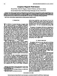
Figure 5. The resistance of a magnetoresistor made from n-type lnSb a s a function of applied magnetic field at the different temperatures indicated (Heremans et a/ 1993). (1) when both the electron density and the electron mobility we high, the electrical conductivity is high; and (2) the mobility p decreases as the doping level is increased, because of scattering of electrons by ionized impurities. A low value of resistance is undesirable in a sensor because then the current consumption and heat dissipation are high, and the output voltage per unit current, or Sf,is low. The ideal resistance of a magnetoresistor is in the range 500 f2 to 5000 Q. The only two free design parameters are the thickness f and the number Ne, of resistive elements connected in series: Si N e , / t . Increasing N,I increases the size of the device and thus its cost. Decreasing the thickness t is the most elegant design solution, and the ideal device is thus made from a two-dimensional electron gas. Modulation doping could increase the carrier density without inducing too much ionized impurity scattering, which is the dominant scattering mechanism in bulk n-type InSb doped above 10'' ~ m - ~even , at room temperature (Zawadzki and Szymanska 1971). Earlier devices were made either from bulk InSb or from evaporated thin films. The first technology is still used in commercially available devices: Siemens AG (1989) uses a manufacturing process based on InSb boules that contain needle-like precipitates of metallic
-
1154
NiSb (Weiss 1969). The metallic needles serve the same purpose as the lateral contact stripes in the device shown in figure 4: they short out the Hall voltage so that a large magnetoresistance appears. Devices are made from the boules by slicing wafers and lapping them to the desired thickness. Thin films of InSb have been prepared by thermal evaporation onto a glass or Si02 substrate. Electron beam recrystallization (Teede 1967) has produced films with mobilities rivalling those of bulk InSb (for instance, a 3.4 p m thick film with a low-temperature electron density of 4.2 x lo1' cm-3 had a 300 K mobility of 60 800 cmz V-I s-I ). Wieder and Collins (1968) even describe a technique in which In-rich material is zone recrystallized in such a way that I~ needles are precipitated in the geometry suitahle for 'shorting bars'. Many other substrates have been used (Partin and Heremans 1993) and many fabrication technologies have been described (Kataoka 1974). In our experience these films have a reliability problem when subjected to thousands of thermal cycles over a wide temperature span, such as -40 "C to 200 "C. Heteroepitaxial films of InSb have recently been grown on insulating substrates. CdTe is the substrate that has a lattice constant most closely matched to InSb, but InSb and CdTe have very different optimum growth temperatures. As a result, CdTe layers of good quality can be grown on InSb, but not vice versa. The interface is not abrupt, and is chemically complex (Zahn et al 1989). Growth of InSb on CdTe has been achieved (Golding et a[ 1990). but is quite delicate, and mobilities of only ahout 25 000 cmz V-' s-' were obtained. InSb growth on GaAs by MBE and MOVCD has been very successful, in spite of the 14% lattice mismatch between the two semiconductors. References include, for MBE growth: Oh e t al (1989), Williams et al (1990), Tsao (1991). Chyi eta1 (1989). Davis and Thompson (1989), Davis et al (1990); and for MOVCO growth: Biefeld and Hehner (1990). InP is another insulating substrate with a slightly smaller lattice mismatch (10%) with respect to InSb. MBE growth on that substrate has been described by Partin et al (1991,1992a). A few groups have successfully grown IuSb on Si, with or without a GaAs buffer layer (Rao et al 1988, Chyi et al 1989, Dobbelaere et a1 1989). Previous reliability studies (Partin et al 1992b) have found the InSblGaAs and InSbiInP systems very satisfactory for practical devices, and further research is still under way for devices made from InSb/Si. These developments have brought InSh-based magnetic field sensors closer to mainstream semiconductor technology, since now amplifiers and signal conditioning electronics can be integrated into the sensor substrate. The magnetoresistor shown in figure 4 was prepared from a 2 pm film of 1nSb:Te with a room-temperature electron density of 6.4 x 1OI6 cm-3 and mobility of p r 45 300 cmz V-' s-l , grown on insulating InP by MBE. A serpentine current path was then etched as a mesa in the film. Evaporated contacts define 21 rectangular elements with large W / L ratio, connected in series. The resistance of a similar device, with larger Ne,, is shown in figure 5.
Solid state magnetic field sensors and applications
a K
\
6
K
a 4 2 -
0 0.0
0.2
0.4
0.6
0.8
1.0
1.2
B (T) Figure 6. The resistance of a magnetoresistor made from epitaxial lnAs on GaAs as a function of applied magnetic field. The film is undoped, and has a surface accumulation layer with an areal density of about 6.5 x lot2 cm-' and a mobility of about 21 000 cm2 V-' s-l at room temperature. The recent use of two-dimensional electron gases in magnetoresistors gives the best compromise between high electron density and high mobility, while maintaining a reasonably large resistance per device (Heremans et a1 1990,1993). Devices based on nearly twodimensional electron gases have so far been made from InAs. The resistance as a function of field and temperature of such a device is shown in figure 6 (Heremans et a1 1993). Two-dimensional effects in InSb have, until now, been limited to accumulation layers in MIS stmctures (Daerr and co-workers 1975,1978, Horst et a1 1985, Merkt et a1 1986, Sikorski and Merkt 1990), and to delta-doped samples (Skuras etal 1990, Williams etal 1990, Yang et a1 1992). No improvement in the roomtemperature mobility of these layers has been observed over the mobility of comparably doped bulk films. This is still an active area of research. A comparison of the relative change in resistance is shown in figure 7 for magnetoresistors made by the different techniques described. Also shown is the influence of the n-type doping level (with Te) on the characteristics of thin film InSb devices. At high temperatures, where the design i s most critical, a donor density of l O I 7 cmm3 does not affect the sensitivity significantly.
2.3. Hall generators Hall sensors have recently been reviewed by Popovic (1991). Commonly used Hall generators are made from slabs of semiconductor shaped in one of the geometries shown in figure 8. The simple rectangular geometry figure 8(a) was treated in section 2.1, and 8(b) is the van der Pauw (1958) geometry. In geometries 8(b) and S(c) current and voltage wires are interchangeable. The cross geometry S(c) improves the efficiency; the butterfly geometry 8(d) results in a sensitive device. Geometry 8(e) is used in measurements of materials parameters pxx and pxy because it minimizes the geometrical magnetoresistance.
-o,'oo., ,o,'
,
T
1 ,
I , ,
,
'YC)
200
300
Figure 7. Fractional change in resistance
[R(B= 1 T)-R(O)]/R(O) as a function of temperature
for magnetoresistors made from MBE-gmwn epitaxial lnSb doped to different electron densities, and for a device made from epitaxial lnAs with a surface accumulation layer. Also shown is the response of a device made by Siemens (FTP412L100)from doped bulk lnSb and mounted on a ferrite flux concentrator.
la1 Rectangular
(b) van der Pauw
r LCI
Id1 Buiterfly
cross
-WL (el reslstlvlty and
~ a l icoefficlenl mea5urement5
Figure 8. Geometries used for Hall devices. A four-terminal device analysis (Weiss 1969) of the Hall device determines the sensitivities. Consider the device in figure 1. Connect its current contacts to a current source, which supplies a current I,, under a potential V,. Connect its transverse (Hall) contacts to a load resistor RL. which draws a current 10 under a potential Vo. The four-pole equations of the Hall generator are then:
+ R , Io Vo = Rxyli + RyyIo. V, = R,, I;
(23) (24)
From symmetry considerations (Buttiker 1988):
Ryx(W = -R.ry(-B).
(25)
The output impedance of the device R , can be calculated from the geometry using either conformal 1155
J Heremans
mapping or numerics, as outlined in section 2.1. When the Hall contacts are almost ‘point contacts’, i.e. very small compared with the sample length, an approximate expression for R, is
-
Ryy (2pA,/zr) In(W/S)
(26)
where S is the length of the Hall contact (under the assumption that S < W c L) (Popovic 1991). From equations (23x26) we can derive a number of figures of merit for the device, depending on the nature of the circuit. Usually, the devices are optimized for either power efficiency q or for maximum Hall voltage V, per input current I j (similar to Si, equation (17)), or for maximum Hall voltage Vo per input voltage (similar to S,, equation (18)). The power efficiency is: Vola q=-=
Vi Ii
REyRL (Rxz Ryy - R,: Rxx R L ) ( R ~ RL)‘
+
+
(27) This efficiency is optimized when the load resistor is ‘impedance matched’ to the generator and has the value:
R,,
+
= Ryy(I /3*)”’
(28)
The maximum efficiency when RL = R L O is~ then: (1
vopt
+ /32)”2
= (1 + /3’)’/*
-1
+1
’
For a Hall plate with a symmetric geometry it can be shown that
/3 N tan@). H ( e , L / W = l)/R(e, L/w = I). (31) Note that ‘impedance matching’ of the load resistor to maximize the power (as opposed to the efficiency) delivered to it is achieved when RL = Ryy. The current and voltage sensitivities are Si and S,, defined in the following two equations. They are calculated assuming an open output RL = CO, that the Hall sensor is made in a rectangular geometry with L > W, and from a material for which equations (9)(1 1) hold
Equations (27)-(33) show that the efficiency q is mostly proportional to the mobility of the semiconductor, while the most sensitive devices are thin, have a low carrier density, and are made from a high-mobility semiconductor. 1156
In some applications a linear dependence of Rxy on the field B is desirable. The length of the Hall contract, parameter S,is often manipulated to influence the linearity of the response. With the prevalence of numerical processing of Hall signals in metrological applications, this criterion is now less important than it used to be. TWO other quantities must be considered in Hall effect devices: the offset voltage V o ~and the noise voltage VN. Offset voltages Vow are due to imperfections in the device fabrication, typically nonuniformity in the material properties or thickness, In materials with a and contact misalignment. high magnetoresistance, either geometrical or physical, offset voltages may become field dependent. Offset voltages can be induced by mechanical stresses, if Such stresses the semiconductor is piezoelectric. can be induced by the device package. The noise voltage VN at the output terminals is due to l/f noise and thermal noise; l/f noise (Weissman 1988, Vaes and Kleinpenning 1977) dominates at low frequencies, thermal noise at higher frequencies. It is convenient to add V0s and VN to obtain an ‘effective’ noise signal, and then to define a signal-to-noise ratio SNX: sm = vHall/(voff
+ VN).
(34)
This quantity is given by Popovic (1991) in each of the three frequency domains (DC, low frequency and high frequency) and is nearly a linear function of mobility. This brings us to the question: which materials are most suitable for Hall sensors? Voltage sensitivity Sv, efficiency and SNR are increasing functions of mobility, which again points to narrow-gap semiconductors, such as InSb and InAs. For high-temperature operation, these need to be heavily n-type doped. This negatively affects Si, as it did for magnetoresistors. In the case of magnetoresistors, this could be counteracted by adding rectangular elements in series (Ne,), which is impossible to do for Hall sensors. Very simply stated, magnetoresistors have an output voltage that is almost quadratically dependent on mobility at low fields, while the Hall voltage of an unloaded sensor only depends on the areal electron density of the device. The use of high-mobility semiconductors in Hall sensors is thus less critical than in magnetoresistors. and is really only warranted in applications in which the device is driving a load or when the SNR becomes an issue. Still, most Hall senson are made from n-type material, because electrons have better mobilities than holes in Si and G A S . Hall sensors, like magnetoresistors, are more sensitive when made very thin, and are therefore often made from inversion layers, accumulation layers, or thii ion-implanted layers. Silicon Hall generators can be made using an inversion layer in a metal-oxidssemiconductor (MOS) structure, or by ion implanting an n-type doped region of the desired geometry in semi-insulating or p-type GaAs, or p-type Si, techniques described by Popovic (1991). Bipolar integrated circuit technology is also used (Popovic 1991). The vast majority of Hall devices are
Solid state magnetic field sensors and applications 200
100
50
-1
E
S
0
v
- 100 \
9
>
50
0
0.0
0.4 0.6
0.2
0.8
1.2
1.0
-,',
(TI 1300
160-
, .cE -. l
z
o
o
~
g1100 \ 1000
-4
x
3
U
aoo0.0
0.2
0.4 0.6
0.8
1.0
U
1.2
8.0 0.2
0.4
0.6 0.8
1.0
8 (T)
Figure 9. Hail resistance (top) and input resistance (bottom) of an ion-implantedGaAs Hail sensor (Siemens KSYlO) as a function of field and temperature.
Figure 10. Hail resistance (top) and input resistance (bottom) of an i n k Hail sensor, deposited on GaAs.
made from silicon, the preferred semiconductor material for low-temperature applications (T e 150°C) that are very cost sensitive and do not require operation above I O to 20 kHz. Amplifying and signal processing electronics can be integrated on the same chip as the Hall sensor. The bandwidth is limited by the SNR and the gain of the integrated amplifier. There are position sensing applications in which the bandwidth of Si Hall sensors becomes a limitation, for instance, when an angular accuracy of better than a few degrees is needed on a shaft rotating at IO 000 rpm, a situation which occurs in some brushless motors. GaAs is used in Hall devices that operate up to higher temperatures, because it has a higher band gap than Si and hence a lower intrinsic canier density. The active region is most often made by ion implanting an n-type layer on a p-type or insulating substrate. Figure 9 (top) shows the output of an ion-implanted GaAs Hall generator (Siemens KSYlO), made in geometry 8(c). The ordinate is the Hall resistance, i.e. V x y / I ,the ratio of the output voltage to the input current. This device is quite stable with respect to temperature in the range from -40 to 200°C. The input impedance V x r / l ,is shown in figure 9 (bottom). High-sensitivity devices, which can measure fields
down to T (1 pG), require optimization of the and are often made from InSb (Kotera et al 1979, Kleinpenning 1983). InAs is used in commercial Gaussmeters. In applications in which a substantial current is to be drawn from the sensor's output, InAs or InSb-based sensors are used, because of their better efficiency. Kotera et a2 (1979) and Kleinpenning (1 983) describe devices that are made from evaporated and recrystallized InSb, already described in the paragraph on magnetoresistors. The more recently developed epitaxial InSb or InAs grown by MBE or MOVCD on semiinsulating GaAs, InP or Si substrates, and described in the section on semiconductor magnetoresistors, are candidate materials for Hall sensors. A mesa of the desired geometry can be etched into such a film, and equipped with current and voltage contacts. The input and output characteristics of a Hall generator made from an epitaxial InAs etched as a mesa in butterfly geometry are shown in figure 10. The active region of the device is an accumulation layer which occurs at the air interface of InAs, as in the magnetoresistor shown in figure 6. The input and output impedances are almost ten times lower than for the GaAs Hall sensor figure 8, while VxJI is only about two times lower around room temperature. SNR,
1157
J Heremans
...-..
.
.~ Figure 12. A two-drain magnetotransistor made as a mesa from an epitaxial film of lnAs on GaAs. ... ,,.. .
Figure 11. Dual drain in-plane magnetotransistor, sometimes called MAGFET. The ratio of current drawn into each of the drains io the source current is shown in the bottom figure, as a function of Hall angle B and length to width ( L : W ) ratio. These calculated curves assume that a constant potential is maintained between the source and each drain, and that there is no gradient in carrier density in the slab. 2.4. Magnetotransistors
A large variety of geometries has been used to exploit the influence of the Lorentz force on the flow of charge carriers in transistors (Baltes and Popovic 1986, Kordic 1986). Typically, magnetotransistors can be made as PET transistors with two drains (MAGFETS), or bipolar transistors with two collectors. The applied magnetic field distorts the current lines and favours current flow into one of the two collectors or drains. A typical implementation of a dual drain MAGFET is shown in figure 11. The device consists of a rectangular slab of degenerate semiconductor with three terminals, one source and two drains. The source current IS is distributed into two drain currents IDIand IDz.Because of the symmetry of the device, in the absence of field: Io1 = Io2 = Is/2. A magnetic field perpendicular to the chip surface causes a deflection of the current lines towards one of the two drains. The bottom of figure 11 shows the calculated ratios I D ~ / I Sand lnz/ls as a function of magnetic field (tan(@)) for different values of the length to width ratio (L : W ) of the rectangular device shown. The two drains are each assumed to be W/2 long, but not to touch. The calculations are performed numerically, using equation (15). and assuming that the carrier concentration is not a function of the magnetic field. MAGFETS can be made from the same materials as Ha!l sensors, typically accumulation or inversion layers, or ion-implanted or epitaxial layers. In silicon, 1158
,
complementary magnetic FETS can be made using CMOS technology, and consist of a dual drain n-channel device and a dual-drain p-channel device. Note that the gate electrode voltage does not need to be varied during operation: its only purpose is to create a channel of the desired surface density. In that sense, these devices are not strictly transistors. MAGFETS can be made from InAs, using the natural accumulation layer of electrons at the interface with their native oxide, like the similar Hall device (Heremans er a1 1993). Such an InAs-based device is shown in figure 12. Similarly, GaAs/AlAs interfaces with active two-dimensional electron gases have been used by Nathan er al (1990). In dual-drain MAGFETS, the useful output voltage is measured as a voltage drop V, between load resistors connected to the drains. The characteristics of the device in figure 12, measured with a constant current source I connected to each drain, are shown in figure 13. The voltage imbalance is Vxy,the source-to-drain voltage is V x x ,The device behaves very much like a Hall generator. Bipolar transistors can be designed to be sensitive to magnetic fields in different ways: some transistors have field-dependent current gains, others are designed with dual collectors. They can be made vertically or horizontally. The magnetic field can act in three different ways. (1) The Lorentz force can act on the minority carriers in the base region, or in the basecollector depletion layer, or in the low-doped collector region itself. (Strictly speaking, these devices should be described in the next section.) (2) The Hall voltage can be designed to deflect the majority carriers in the base region. (3) The Lorentz force can act on both types of carrier, which then will adjust their concentration to maintain space charge neutrality at each point. In general, all three effects coexist to some degree. A lateral pnp double-collector magnetotransistor with large sensitivity was described by Popovic and Baltes (1983). The device is shown in figure 14. The useful output voltage is the differential voltage obtained between two load resistors connected to the two collectors. The device in figure 14 had an emitter purposely designed with a low efficiency. The magnetic field operates on the larger majority carrier current in the base (effect (2)), yielding a larger Hall field than if the Lorentz force were operating on the minority carriers alone. Furthermore, the base region was surrounded by a deep diffusion ring
Solid state magnetic field sensors and applications Table 3. Current (Si) and voltage (E+) sensitivities at Hall sensors of various geometries, a MAGFET, and a magnetoresistor at 2O"C, made from the same epitaxial lnAs film. The sample geometries refer to figure 8. For comparison the last two lines give data for a Si and an lnSb device.
20°C of
5 = 0.19 T
si
(aT-') Hall rectangle 8(a) Hall cross 8(c) Hall butterfly 8(d) MAGFET
(L = w )
95 102 88 42 4000
Magnetoresistor Si Hall (Popovic 1991) lnSb magnetoresistor 6700
s,
(T-')
5=1.0T
si
1.3
94 a8 a0 40
0.85 1.3 0.66 1.5 0.07 3.0
s,
(a1-') (T-') 0.59 0.42
0.60
a600
0.29 1.0
10200
1.0
300 250
,-.
2 200 0
v
- 150 \
::100
>
Figure 13. Differential resistance (top) and input resistance (bottom) of a MAGET made from an lnAs film with a surface accumulation layer, as a function of field and temperature. V, is the voltage between the source and one of the drains.
account, the sensitivities of current magnetotransistors are not superior to those of Hall generators. In fact, if we assume that there is no blocking pn junction in the magnetotransistor for figure 14, and that all contacts are ohmic, the device is equivalent to a vertical Hall plate. Consider the vertical cross section in figure 14. If the base contacts BL and ER were extended to infinity, left and right, one could use conformal mapping to transform that vertical cross section into a rectangular Hall plate, such as figure 1, with E and (BL BR) the current injecting electrodes and CL and CR as Hall voltage electrodes. Given the large variety of effects involved in magnetotransistor operation, they still offer potential for optimization (Nathan et al 1989). However, as they exist today, magnetotransistors behave essentially as Hall plates. Sensitivities Si and S, can be defined for MAGFETS by analogy:
+
- - - - --- - - - - - - - - --
I - - - - - - - - - - - - - -I II
2.5, Comparison of majority carrier semiconductor magnetic field sensors
Figure 14. Double-collectorlateral magnetotransistor. The magnetic field U , which lies in the plane, modulates the ratio of the currents between the emitter (E) and each of the collectors (C,on the left and Cn on the right). A diffusionring (broken line) confines the base current. The base contacts are BL and BR (after Popovic and Bakes (1983)).
(see figure 14). which confines the base current to a thin slab perpendicular to the direction of the magnetic field. Under optimal operation conditions, magnetotransistors can achieve sensitivities (dIc/dB)/Ic as high as 4 T-]. This seems far superior to those of Si-based Hall plates. The devices however require high bias currents. If both base and collector currents are taken into
Semiconductor magnetoresistors, Hall generators and most magnetotransistorsoperate through the influence of the Lorentz force on majority carriers. In this section, the sensitivities Si and S, of the different sensors are compared. A comparison at 20°C and at fields of 0.19 T and 1.0 T is given in table 3 for Hall generators of various geometries, a MAGFET with L = W (see figure ll), and a multi-element magnetoresistor made from the same semiconductor: the epitaxial InAs layer on insulating InP, in which the transport is dominated by a nearly two-dimensional accumulation layer, with 6.5 x 10" cm-* and p N an area density Ns 21000 cmz V-' s-' (Heremans et al 1993). Data on a Si Hall device (Popovic 1991, p 208) and on InSb magnetoresistor (figure 5) are also given. The
-
1159
J Heremans
exact geometry of the Hall device has, in final analysis, only little effect. Of course, the output impedance R,, of the cross shaped devices (figure 8(c)) is much lower than that of rectangular (figure 8(a)) or butterfly shaped (figure 8 ( d ) ) devices. The obvious advantages of magnetoresistors are mitigated by the fact that their response to field is essentially quadratic: at very low fields they become less responsive than Hall sensors and they do not detect the polarity of the field. Their current sensitivities Si can be increased by simply increasing the number of elements Nei until some extraneous limiting factor is reached, such as power supply compliance, input impedance of the voltage readout, or, most commonly, device cost. No simple way is known to the author to connect hundreds of Hall devices in series and add their Hall voltages, unless AC excitation and transformers are used (Weiss 1969).
4'
H
/"
Figure 15. A magnetodiode consisting of a slab of lightly doped semiconductor with heavily doped n and p regions. The surfaces of the lightly doped region have veiy different recombination rates RI and R2.The longitudinal voltage applied to the diode in folward biasing injects both electrons and holes in the lightly doped region. The magnetic field H can either push both types of carrier towards the high recombination surface, in which case the current decreases, or towards the low recombination rate surface, when the current is increased. The current against field relation under a given bias is schematically given on the right (after Cristoloveanu et a/ (1983)).
3. Other semiconductor sensors
3.1. Magnetodiodes Figure 15 shows a schematic diagram of a magnetodiode (Cristoloveanu et al 1983). An intrinsic region in the middle is contacted to a heavily n-type region on one side and a heavily p-type region on the other. The magnetodiode is different from a simple pi-n diode because one of its faces has been treated to form a surface at which electrons and holes readily recombine (the face with recombination rate RI in figure 15). These surfaces can be prepared, for instance, by mechanical abrasion or using ion implantation damage. Some magnetodiodes exploit the high recombination velocities at the silicon-sapphire interface. The other face (with recombination rate Rz in figure 15) is made as perfect as possible, by etching for instance, to keep the recombination velocity low. When a bias voltage is applied as shown in figure 15, electrons are injected from the n+ electrode into the intrinsic region, as are holes from the p+ region. In the presence of a magnetic fieId as shown, the Lorentz force acting on both types of carrier pushes them in the same direction. If the two types of carrier are deflected by the magnetic field towards the face with high recombination rate R I , they recombine there. and the current flow is impeded. If they are deflected toward the other face, much less recombination takes place and more current flows. Current-voltage characteristics of an early Ge-based p-i-n diode at room temperature at different field values are shown in figure 16 (Yamada 1968). Sensitivities can be up to 1000 times higher than those of Hall generators made from similar materials. Discrete magnetodiodes were made from Ge, Si, GaAs, silicon-on-sapphire, and Si-Mos technology (Baltes and Popovic 1986). This elegant device has been commercially availablet but has a large temperature coefficient: the resistance of the Ge diode doubles for every temperature excursion of 17°C.
t European Electronics Products Corp.,
10150 W Jefferson
Boulevard, Culver City, CA 90230, USA. Catalogue AHYlO 1160
'*I ,
W8 O
I
Z
I
I
I
I
( I
3
4
5
6
7
V(V0lt)
Figure 16. Magnetic field dependence of the currentvoltage characteristics of an early Ge magnetodiode (after Yamada 1968).
3.2. Carrier domain magnetometers Melngailis and Rediker (1962) described an InSb device which measures the influence of a magnetic field on an injection plasma. While the first device was made from InSb cooled to liquid nitrogen temperature, many authors have implemented such devices in siIicon and obtained room temperature operation. The silicon work has been reviewed by Baltes and Popovic (1986) and Popovic (1991), and all relevant references can be found there. I only describe here the device of Goicolea et al (1984). in order to compare it with other sensors in a later section. This device, shown in figure 17, is made using a bipolar epitaxial transistor process, as a four-layer npnp structure. The structure is equivalent to merged npn and pnp transistors with a shared collector-base junction, which is reverse biased. The emitters of the transistors are connected to current sources IEpand IEN. Holes are injected from the p layer ( ( d ) in figure 17) and collected in the p layer ( b ) , through contacts V,I and Vp2. Similarly, electrons are injected from layer ( a ) via the base (6) of the npn transistor, to be collected in the layer (c) through the contacts V,, and Vn2. Both electron and hole currents in layer (c) are localized in a small current filament of width A. The formation of this injection plasma is due to an increase in carrier lifetime in that region as the injection level is increased.
Solid state magnetic field sensors and appkations 4. Integrated semiconductor magnetic field sensors
n+
----
.
.
Id1 I
I/(
Y X ’
Figure 17. Carrier-domain npnp magnetometer, alter Goicolea et a/ (1984). Electron and hole currents coexist in a high-current density filament in region (c). The magnetic field, oriented along t h e y axis, deflects the entire filament left or right along the x axis. This results in a current or voltage imbalance between either electrodes V,, and Vn2.or V,, and V,,, depending on the external circuit.
This in turn is due to a saturation of the traps that promote recombination. The increase in lifetime lowers the local resistivity of the material, which enhances the injection of carriers in that region, thus providing a positive feedback mechanism that stabilizes the filament of electron-hole plasma. When a magnetic field is applied along the y axis, this filament is displaced either towards contacts V,,, and V,, or towards V.2 and Vp2, depending on the polarity of the field. Electron and hole currents are displaced in the same direction. Goicolea et id (1984) describe three possible modes of operation of the device, depending on the loads connected to V,,, V,,z and Vpl, Vp2. The device gives essentially a linear response with field, either as A V / V or AI/[ measured differentially between contacts 1 and 2. Sensitivities are A V / V = 2.4 V T-’ and AI/[ 2: 3 x IO-’ A T-’ ( B < 0.15 T). The benefit of forming an injection plasma is that i t enhances the sensitivity by a factor estimated to be 10 to 100, proportional to I/h, over a similarly shaped dualcollector magnetotransistor. This is because the plasma is confined to a filament with high current density. The filament does not have boundaries on which a Hall voltage can develop which counteracts the Lorentz force, unlike conventional majority canier devices such as magnetoresistors and Hall sensors. The entire filament is deflected by the magnetic field. It is possible to operate carrier domain magnetometers in a frequency mode. In the device shown in figure 17, one can induce an unequal division of current between the two bases, which pushes the filament towards one side. With a positive feedback loop, the filament can be made to oscillate. A magnetic field applied along the y direction induces a change in the frequency of this oscillation. Again the response is linear, and is about 5 x lo7 Hz T-’ over the field range 3 x IO-’ T < B < 8 x IO-’ T. These promising devices unfortunately experience problems with temperature stability.
-
Silicon Hall generators are mostly used with on-chip amplification and signal conditioning electronics. Most integrated magnetic field sensors are rather simple combinations of the sensor with a current supply, an amplifier and, when hysteresis is desired, a latching circuit. The voltage output of a Hall generator is usually low, especially when smallsurrent consumption is a design requirement. This implies that high-gain amplifiers must be used and the trade off between gain and bandwidth depends on the sm. Hall generators give a differential output, which may have to be converted to a single-ended output. For high-temperature applications, such as many automotive ones, GaAs sensors with integrated electronics are being developed (Itakura et al 1989). If 111-V compounds have to be used rather than Si, InAs- or InSb-based magnetoresistors grown on an insulating GaAs substrate in which the amplifiers/signal conditioners can be integrated, are competitive with GaAs Hall generators, because they generate a higher output voltage in moderate magnetic fields (see section 2.5). Magnetoresistors give a single-ended output voltage, unfortunately with a high offset bias, which the integrated signal conditioning circuit has to compensate for. Magnetotransistors can readily be integrated. Complementary pairs of magnetic FETS can be incorporated into a configuration reminiscent of a CMOS differential amplifier (Baltes and Popovic 1986). Bipolar dualcollector magnetotransistors, such as that shown in figure 14, can be integrated into a magnetic operational amplifier using analogue bipolar technology (Maenaka et al 1990). Carrier domain magnetometers as shown in figure 17 are not so easy to integrate, because the substrate is an active electrode. There are, however, other geometries for these devices (Baltes and Popovic 1986).
5. Magnetic metal film magnetoresistors
5.1. Anisotropic magnetoresistance Ferromagnetic metals and alloys have an anisotropic resistivity in a magnetic field (McGuire and Potter 1975). In a single-domain film of a ferromagnetic metal, the magnetic moment vector tends to lie in the plane because of the large demagnetization factor. The electrical resistivity measured when the current density vector is parallel to the moment pII can be different from the resistivity measured with the current perpendicular to the moment p~ (see figure 18). This experimental fact, which is surprising in cubic metals, has been explained by an anisotropy in the scattering of the electrons (Campbell et a1 1970). It is akin to the physical mechanism underlying the anomalous Hall effect (Bergmann 1979). Schematically, the electrical conduction in these metals and alloys is mostly due to s electrons and an important scattering mechanism is 1161
J Heremans NO EnerMl Field
-
0
0.5
1.0
1.5
2.0
25
B(T)
Figure 18. Magnetoresistivityof Ni-Co at room temperature as a function of field, applied parallel p , or petpendicularly pL to the easy axis of magnetization (after McGuire and Potter 1975).
scattering of the s electrons on d electrons. Spin-orbit coupling introduces anisotropic differences in scattering rates between s electrons and spin-up or spin-down dstates. At room temperature this effect is maximal in Ni,Fe,-, alloys, for x Y 0.9, where the relative difference in resistivity A p / p can exceed 5% and in Ni,Col-, alloys for x Y 0.8, where Ap/p > 6%. In practice (Thompson et al 1975), Ni,Fel-, alloys in the permalloy range (x N 0.81) are used because they have zero magnetostriction. This avoids stress related problems, but limits A p / p to 2 or 3%. The anisotropy in the resistance of permalloys and other magnetic films can be used to make magnetoresistors (Thompson et ai 1975, Dibbem 1986). These devices are made from thin films because the electrical resistance of thin film devices is higher than that of bulk samples, which is desirable for the same reasons as in the case of semiconductor magnetoresistors, and because thin layers can be made to behave like a single magnetic domain. Their magnetization with no applied field follows one single well defined direction in the plane, called the easy axis, set during manufacture. A schematic drawing of the device is shown in figure 19. There is an angle 8 between the direction of current I flow, and the direction of the magnetization M along the easy axis. As an external magnetic field H is applied to the sample, the direction of ‘the magnetization M is rotated away from the easy axis, and the angle 0 changes. Since the resistivity along the magnetization direction is pu, different from that perpendicular to M ,p ~ the . total resistance of the film becomes a function R ( H ) of the applied field X,via the dependence of B(H): R ( H ) = (1/WO[p.t
+ (PI - p d cos*QI.
(37)
The output of such a sensor typically decreases from its value R ( 0 ) at zero field to a minimum value R(H,) reached at a saturation field H,. The output as a function of field is often characterized by the quantity A R / R , which is defined in the literature as [ R ( H ) R(H,)]/R(H,) or as [ R ( H ) - R(O)]/R(O). In the case 1162
In Exlemal Field H
Exlwnd Field
i3m Magneliralhn
Easyhis
Figure 19. Magnetoresistance in a thin film of permalloy. In the absence of field (top), the current makes an angle
B with respect to the magnetization M, which lies along the easy axis. An in-plane applied field H (bottom) rotates the magnetization M. The anisotropy of the resistivity and the dependence of B on the field lead to a change in resistance of the strip (adapted from Lenz 1990).
of devices based on the anisotropic magnetoresistance, A R / R is a few per cent, so that the difference in definitions is not relevant; but this is not the case for multilayer magnetoresistors described later. A typical output of a permalloy device is shown in figure 20, after Thompson er al (1975). The output of these devices can be linearized (Dibbern 1986) by one of the following techniques. The sensor element can be magnetically biased by a permanent magnet, which can be a thin film of a magnetic material. Alternatively, the current through the sensor can be sent at a non-zero angle 0 at zero field, so that equation (37) becomes linear in H over a limited range of 8 ( H ) . This can be done by defining the resistor element along a specific direction, or by using slanted current injector contacts, called ‘barber poles’. Kitada and Shimizu (1992) describe linearization schemes for tWo differential magnetoresistors connected in series, a three-terminal device. They use thin film magnetic biasing as well as current biasing, but the former technique is better. By biasing the two magnetoresistors in the bridge with fields of opposing polarity, they obtain a differential response that is much higher than in other linearized sensors. 5.2. Magnetically coupled multilayers
An effect called ‘giant negative magnetoresistance’ (CMR) was discovered recently in Fe/Cr superlattices and other multilayer systems (Baibich et a1 1988) consisting of alternating layers of magnetic and non-magnetic metals. The magnetoresistance of such a multilayer is shown in figure 21. In the absence of an applied field the magnetic moments of adjacent magnetic layers can be spontaneously aligned either femmagnetically or antiferromagnetically, depending on the thickness of the layers. The polarity of this alignment varies periodically with the thickness of the non-magnetic layer (see, for example, Mosca et ai (1991)). When the magnetic layers are aligned antiferromagnetically, the
Solid state magnetic field sensors and applications for that Cu thickness, the lower value of H, results in an increased slope dR/dH, which may make such material preferable in sensors.
53. Uncoupled ferromagnetic multilayers
-,
2 4 6 8 ) 0 1 2 MAGNETIC FIELD (10- T)
0.0
Figure 20. Relative change in resistance A R J R at room temperature of a permalloy sample 200 A thick, as a function of a field amlied in the Dlane of the film. alona the hard axis. The current is applied along the easyaxis rafter Thompson (1975)).
0 .4
-3
.2
.1
is
4 ?
0
.
,
1
I
2
I
I
3
4
Magnetic Field (T) Figure 21. Relative change in resistance of FdCr multilayers as a function of magnetic field at 4.2 K. The thicknesses of the individual layers (in Angstrh) are given in the figure, along with the number of layers. This effect persists to room temperature (after Baibich et al (1988)).
resistance of the structure is greater than when they are aligned ferromagnetically, due to the spin dependence of the scattering. An external magnetic field can change the magnetic orientation of the layers with respect to one another, and thus change the resistance of the multilayers. The effect saturates at a field H,. The magnetoresistance has been observed both with the current parallel (Baibich et a1 1988) and perpendicular (Pratt et al 1991) to the multilayers. The materials which have exhibited the largest derivative of the resistance with field to date are Co/Cu multilayers (Mosca eta1 1991) in which relative changes of the order of [ R ( N ) - R ( H , ) ] / R ( H , )N 80% have been observed at liquid He temperatures. The temperature dependence of the magnetoresistancein coupled multilayers is moderate and almost linear at higher temperature (Chaiken et a1 1991). A R / R can vary by a factor of almost two between 4.2 K and room temperature (Mosca et a1 1991). The main limitation of G M R based sensors for technological applications is the fact that H, is high. For the Cu/Co (CO layer 15 A and Cu layer 9 A thick) system at 4.2 K, A R / R is 78%. but H, is 0.4 T. When the Cu layer is 20 thick, H, is N 0.04 T (there is a strong hysteresis). Even though A R / R is only 40%
A
-
Dieny and coworkers (1991b,c, 1992) have reported very large magnetoresistive effects in sandwiches ' consisting of two uncoupled ferromagnetic layers separated by a non-magnetic metal. The structure, called a 'spin valve' (sv), is represented by TMUNMRMZAF, where TMl and TM2 are ferromagnetic transition metals or alloys (CO, Ni, permalloy), NM is a non-magnetic material (Au, Cu), and AF is an antiferromagnet (Fe50Mnso). An example of such a system is glass/M/Cu/permall~y/Fe~~Mn~~/Cu (Dieny et a1 1992). where M is a ferromagnetic transition metal or alloy, CO, Ni or permalloy. In these systems, the magnetization of the layer TMI (M) is free to rotate in the applied magnetic field. The magnetization of layer TM2 (permalloy) is constrained by exchange anisotropy through contact with the antiferromagnet AF (Fe~0Mn5~), i.e. the TM2 layer is made to behave as a harder magnet than the TMl layer. The magnetoresistance measured in these systems is much higher than would be expected from the simple anisotropic magnetoresistance, and is attributed to an exchange of polarized electrons from one ferromagnetic layer to the other. An exponential dependence of A R / R on the thickness of the NM layer is often observed. The temperature dependence of A R / R in sv systems is quasi-linear (Dieny et a1 1991a) over the range 4.2 K c T < 350 K, and again A R / R is decreased by a factor of about two between liquid He and room temperatures. The main advantage of sv magnetoresistors in device applications is that they are sensitive at low magnetic fields. The field dependence of the response is very hysteretic and asymmetric owing to the exchange anisotropy. As the field is swept from a negative value through zero, there is almost no change in resistance. At a small positive field, the moment in the free layer switches and A R / R becomes positive, with a change of the order of 4 to IO%, depending on materials and temperature. When the field is increased further, the moment in the pinned layer is slowly reversed and A R / R reNmS to zero. This process is completed after 0.012 T in Co/Cu/Co sandwiches, but in most systems the saturation field is 0.1 to 0.05 T (Dieny et a1 1991b). There can be considerable hysteresis upon subsequent decreases in field. For the purpose of comparing metal magnetoresistors further I have used only that part of the hysteresis loop that shows the largest A R / R at the lowest field. 5.4. Systems without synthetic multilayers
Two groups of workers, Berkowitz et al (1 992) and Xiao et nl (1992) have reported 'giant' magnetoresistance in granular films of Cu-Co, Fe-Cu and Gd-Ti prepared 1163
J
Heremans
by DC magnetron co-sputtering on insulating substrates. The two metals do not alloy, but form small granules in the film through which the current flows. The values of A R / R of these films will be compared in the next section. Moruzzi and Marcus (1992) point out that the binary compound FeRh is a naturally occurring multilayer. .The compound shows a giant magnetoresistance, which they ascribe to a transition from antiferromagnetic to ferromagnetic coupling, similar to the transition in synthetic multilayer;.
10
"'
,--.
1 1
Lc2,cu
\
'
5.5. Comparison of metal magnetoresistors
In figure 22, I compare the relative change in resistance with field of a thin permalloy film, a Co/Cu multilayer and an inhomogeneous CoKu mixture of two sv systems, and a semiconductor (InSb) magnetoresistor (section 2.2). The relative change in resistance A R / R is here defined as IR(B) - R(O)(/R(O).positive number which can be plotted on a logarithmic scale. The abscissa is the value of B . Broken curves are measured around 4.2 K, full curves at room temperature. The permalloy device, which relies on anisotropic magnetoresistance (section 5.1), was measured by Thompson et al (1975) and its A R / R value is shown in figure 20. The two sv films are from Dieny et al (1991b): SVl refers to a film of structure Si/5 x (50 Td62 A NiFe/22 8, Cu/40 A NiFel70 8, FeMn) measured at 4.2 K. Only one branch of the hysteresis curve is shown; the other branch has a slightly lower maximum A R / R ; there is no A R / R in reverse field, At room temperature the maximum value of A R / R of SV1 is about 3%. SV2 has a ColCulCo active layer and exhibits a large 8.7% rise in A R / R for 0.002 T at room temperature. There is no A R i R on the return loop, and only a very small magnetoresistance in reverse field. For SVl and SV2, the field was applied in the plane along the easy direction defined by the exchange anisotropy. The current was perpendicular to the field. The Co/Cu ML sample is from Mosca et a1 (1991) and has a structure 30 x (15 A Co/9 A Cu). It was measured at 4.2 K with the field in the plane along the current direction. In transverse field the maximum value of A R / R is the same but the saturation field is higher. That sample shows only a small hysteresis. Samples with 20 8, Cu spacer layers have HsN 0.04 T, but there is a 0.02 T hysteresis on the magnetic field value at which the resistance is maximum. The Fe/Cr multilayer system, on which Baibich et al (1988) first discovered the effect, gives smaller sensitivities and is thus not shown. The granular films (CoCu gran. in figure 22) are less sensitive. To date only the use of sensors based on anisotropic magnetoresistance has been described in the literature. In these sensors, the maximum A R / R is small ( 2 to 3%). but the very low saturation fields make them most useful for the detection of small fields. Magnetic multilayers show a clear potentia1 to increase the total A R i R by an order of magnitude over permalloy, but the higher saturation fields are a problem. The fields used in 1164
'"""'1
.
'
T = 300 K 5 = 4.2 K
_ .
0 LT
".'""~
)'.''''1
I
MLj
I
10
Figure 22. Sensitivity of different magnetoresistors against magnetic field. The full curves are measured at room temperature; broken curves at or near 4.2 K. 'InSb is the magnetoresistor from figure 5; 'Perm' is the permalloy one shown in figure.20; WI.' refers to an sv device of.structure Si@ x (50 A Td62 A NiFe/22 A Cu/40 A NiFenO A FeMn)/SO A Ta (Dieny et a/ 1991b); 'SV2 is a Co/Cu/Co sv device (Dieny et a/ 1991b); 'Co/Cu ML' is a multilayer of structure 30 x (15 A Co/9 A Cu) (Mosca et a/ 1991); 'CoCu gran' Is a granular, non-multilayer,Co-Cu co-sputtered film (Xiao et a/ 1992). In the lowest field range, simple permalloy devices are the most sensitive; sv devices hold promise for the to lo-* T range but, at higher fields, semiconductor devices give up to ten times more magnetoresistance than metal multilayers. magnetic positioning systems are of the order of 0.1 T, and InSb-based magnetoresistors are several times more sensitive than the best magnetic multilayer systems in such applications. The addition of exchange biasing layers (sv systems) opens an interesting possibility for to lo-* T. The author is applications in the range unaware of publications describing the use of multilayers in sensors up to now. Reliability issues, such as the behaviour of the films during high-temperature soaks when diffusion may occur at the interfaces, have not yet been addressed in the published literature. 6. Comparison between the different sensors
The selection of which sensor to use for which application depends on the magnetic field range to be detected and the relative sensitivity of the sensor in that range. Other factors must be considered, such as reliability, temperature range, power consumption, size and linearity. Many solid state sensors have the great advantage of being integrable with amplification and signal processing circuits, resulting in very cost competitive systems. In table 4, the current and voltage sensitivities Si and S, at 20°C of some majority carrier semiconductor sensors, a carrier domain sensor and a Co/Cu 'giant magnetoresistance' material are compared. The quantities are defined as in section 2.5. In figure 23, the output voltage of a number of solid state sensors is shown at Z O T , as a function of applied magnetic field.
Solid state magnetic field sensors and applications These sensors are a thin film InSb-based magnetoresistor n-doped at 6 x 10l6 (Partin ef a1 1992b, Heremans et al 1993), a thin film permalloy-based magnetoresistor (Nippondenso), an ion-implanted GaAs Hall generator (Siemens KSY-IO),and a Si-based Hall generator with integrated on-chip amplification (Allegro 3501). The outputs of the sensors in figure 23 are very different in nature. In order to make a meaningful comparison, the figure of merit used to construct figure 23 is the difference between the output voltage of the sensor at the field given in the abscissa and at zero field, divided by the supply current. For the GaAs Hall generator it is the Hall voltage divided by the longitudinal current at each field. The Si-based Hall sensor with amplifier was supplied with a 12 V bias and drew a current of about 7 mA. At zero field its output was around 3.7 V. The output shown in figure 23 is the difference between the output voltage in field and this 3.7 V, divided by the supply current. For magnetoresistors, the output is the difference in resistance under an applied field and the resistance at zero field. Both magnetoresistors whose performance is shown have zero-field resistances around 1 kQ. At the lowest fields, magnetoresistors based on permalloy are most sensitive, but their sensitivity saturates at fields of a few millitesla. Hall generators give a generally linear response to field, while InSb-based magnetoresistorsgive a quadratic relationship. As a result, Hall generators are always more sensitive than InSb magnetoresistors at low fields, and the opposite is true at high fields. The crossover field depends on the technology used: unamplified InSb-based magnetoresistors are more sensitive than the shown Sibased Hall generator with integrated amplifier above 0.03 T. The latter sensor has a cut-off frequency (3 dB) of 25 kHz, because of the relatively low SNR of the Hall elements and the large-gain amplifier used on the chip; this restriction is not applicable to any other sensor reported in figure 23. Summarily, permalloy-based magnetoresistors are preferred for sensing magnetic fields below about 0.005 T, Si Hall sensors with integrated amplification for fields between 0.005 and 0.03 T (if the frequency cut-off is not a problem) and InSb-based magnetoresistors for field ranges above 0.03 T. These are only crude guidelines. When high-temperature (above 170 to 2OO0C) operation is required, GaAs Hall sensors can be considered along with heavily doped InSb or InAs magnetoresistors. 7. Applications of magnetic field sensors
7.1. Magnetic recording heads Magnetic recording film can be magnetized in the direction perpendicular to the film or in the plane of the film (‘longitudinal recording’). Recording heads can use a magnetoresistor or Hall generator. A review of magnetoresistive head technology is given by Markham and Jeffers (1990) and other examples are shown in the Siemens application handbook (1989). Inductive heads can also be used (Jagielinski 1990).
T = 2 0 C
E 1000
lnSb MR Si Hall
v
+
Amplifier
C
\
GoAs Hall
0
3 O
>
10
0.01
B &40)
1
Figure 23. Sensitivity of differentsolid state magnetic field sensors at mom temperature. The sensitivity is defined as the change in output voltage divided by the input current, when the applied magnetic field is changed from zero to the value shown in abscissa. At very low fields, the permalloy magnetoresistor (MR) is the most sensitive. Note that when field changes above 0.03 T (300 G) have to be detected, unamplified InSb-based magnetoresistors are more sensitive than Si Hall sensors with integrated amplifiers. The gain of such amplifiers is limited by signal-to-noiseand bandwidth considerations (Heremans et a/ 1993).
7.2. Memory
Daughton (1992) reviews magnetoresistive random access memory (MRAM), an emerging technology for a non-volatile memory with good write durability, very high cell densities, unlimited read and write cycles, and intrinsic radiation hardness. MRAM is an integrated combination of a non-volatile thin film magnetic storage technology with semiconductor read-out and processing circuits. The storage is based on the magnetic anisotropy of the storage medium. A magnetic field is applied during the deposition or anneal of this medium, which induces a preferred axis of magnetization in the material, the easy axis. The magnetic moment vector will then tend to point in a direction either parallel or antiparallel to the easy axis, and this is the property that represents the logical zero or one. A magnetic field intensity exceeding a certain threshold value is needed to switch each bit from one state to the other. This threshold value depends on the magnetic anisotropy and on the orientation of the writing system with respect to the easy and hard axes. The bit addressing system used is a two-dimensional array of wires. The current through each wire is not sufficient to switch the polarity of the bits along that wire, but the combination of the currents of two wires crossing over one bit will. Reading the bit happens through an array of permalloy magnetoresistors-as outlined in section 5.1 they are sensitive to the direction of the field in the plane. Through a clever geometry, the write and read lines can be made to be the same. The only disadvantage of this type of memory is its access speed of only about 2 p s (compared with 100 ns for conventional semiconductor DRAM). The bandwidth of the device is limited by signal-@noise considerations due to the low 1165
J Heremans Table 4. Current and voltage sensitivities (S, and .%) and Co/Cu multilayer (‘giant magnetoresistance’) field
at 20°C of Si, GaAs, Ge, InAs, lnSb sensops.
5 = 0.19 T Si (st T-‘)
Si Hall (Popovic 1991, p 208) Si magnetotransistor (Popovic 1991, p 280) GaAs Hall (Siemens 1989, KSY10) Si carrier domain (Goicolea et a/ 1984) Co/Cu ML at 4.2 K (Mosca er a/ 1991) G e magnetodiode (European Electronic Products) lnAs Hall (figure 8(a)) lnAs Magnetoresistor lnSb Magnetoresistor
si (n T-‘)
(T-’)
187
0.18
s,
0.07 0.1 190
0.20 0.3 1.o
10000
0
1.0 (at B = 0.1 T)
95
1.3
94
4000 6700
1.5 3.0
8600 10200
sensitivity of permalloy magnetoresistors. Daughton (1992) concludes that the use of GMR materials should improve the bandwidth by an order of magnitude. Another integrated magnetic memory element, the thin film analogue of the ferrite core, was proposed by Prinz (1990). The element can be made from an epitaxial magnetic metal deposited on a semiconductor substrate, such as Fe on Si or GaAs. The iron film is patterned in the shape of a frame with its sides aligned along the magnetically easy axes of Fe. The frame can be magnetized with the moments aligned clockwise or anticlockwise, representing the zero or one states of the bit. The sensor reading the magnetic state of the memory element can he integrated in the semiconductor. The magnetic loop is closed, and very little leakage flux and cross talk are expected. The down scaling of both proposed memory elements is only limited by semiconductor technology, because the magnetic properties ofathemedia are independent of size, down to maybe 200 A. A non-volatile memory array has also been proposed based on the bipolar spin switch described by Johnson (1993). 7.3. Position and speed sensors
Sensors that translate mechanical movement into an electrical signal are becoming very widespread with the increased use of microprocessors. The simplest example of this class of sensors is the potentiometer, but the friction involved in conventional potentiometers makes them less reliable than frictionless methods. Optical techniques (a light emitting diode and a photodetector, with or without fibre optics, for instance) are sensitive to contamination and their applications are limited to protected environments. Magnetic position sensors are based on the use of a permanent magnet whose position is changed with respect of that of a magnetic field sensor. Linear position sensors use a sliding magnet moving with respect to a magnetoresistor or a Hall 1166
s,
(T-’)
B = l . O T.
0.59 1.o 1.o
sensor. Proximity sensors based on similar designs are common, for instance to verify door and hatch closures. Rotary shaft encoders measure the speed and the position of a shaft. A typical magnetic circuit used for sensing the position of gear teeth, machined into an iron or steel wheel, is shown in figure 24. The size and distance apart of the teeth can be used to encode absolute position sensing. Note that the field at the location of the magnetoresistor varies between two non-zero values H- and H-, around an average that is of the order of 0.1 T. This average varies strongly with the distance between the sensor and the wheel, which in turn can have a large variability range during the assembly in a factory. This type of sensor is used to measure the position of the crankshaft and camshaft in a gasoline engine (see figure 25). Its information is fed into the engine control computer, which then determines which cylinder’s spark to fire and when to fire it.
7.4. Brushless motors Brushless motors have applications in video recorders, disk drives, turbopumps and automotive motors. The rotor in such DC motors is a permanent magnet whose position is monitored by magnetic position sensors. The sensors feed their information to electronics that control current flow through the stator windings. Brushless motors are more reliable and generate less electrical noise than their brushed counterparts. Furthermore, the rotor position can be microprocessor controlled very precisely. Complicated rotation patterns can then be programmed in a flexible manner. 7.5. Shuntless DC current measurements
Shuntless DC ammeters can be made from a primary coil wound on a soft iron core. The unknown current 1,. passes through this winding. The resulting flux generates a field that can be detected by the Hall sensor located in
Solid state magnetic field sensors and applications
Figure 24. Rotary shaft position sensor using a magnetoresistor and a cogged wheel. The flux lines are schematically outlined. The field intensity H at t h e sensor location changes from a non-zero minimum value H,,, to a maximum value H,=.
an air gap in the core. The output of the Hall sensor is a measurement of lin,For more precision and dynamic range, a secondary coil is wound around the core, A Current can be made to flow through this secondary, so as to cancel the field in the gap. The Hall Sensor is then used as a null detector and the current through the secondary coil is a measure of the current through the primary.
8. Summary Magnetic field sensors have applications in magnetic recording9 memories and in position* 'peed and proximity sensorS. Magnetic recording has a long and successful history. Non-volatile memories can be designed using field sensors, and hold much promise. Magnetic position Sensors we the most reliable way to translate a mechanical movement into an electrical signal, and become a critical interface component between microprocessors and mechanical systems. New developments are still emerging, even though magnetic field sensors have a long history. The close integration of these sensors with signal conditioning electronics is the goal of much research. Significant evolutions over the last five years include the discovery of magnetoresistance in magnetic multilayers. While these materials have larger saturation fields than anisotropic magnetoresistance (permalloy) devices at present, research in that field is only beginning. Mu1ti1ayer systems Offer many variah1es that cm be tuned, such as the amount of magnetic exchange. They could potentially be used in competitive sensors, but
Figure 25. Crankshaft of a production engine. The arrows point to notches. A magnetic field sensor, which can be a pick-up coil, a Hall sensor or a magnetoresistor, mounted on a magnet as shown in figure24, is insertedin the engine case and measures the passing of the notches. This information is sent to the electronic engine control module which calculates the timing of the spark plugs. research should be aimed at decreasing the saturation field. Narrow-gap semiconductor magnetoresistors give much larger resistance changes than G M R systems. The possibility of growing such semiconductors on insulating GaAs or even Si substrates, forces one to reassess the old notion that InSb and InAs are not practical for large scale production. The substrates can be used to integrate signal processing electronics, One of the more fascinating prospects is the possihility of integrating magnetic circuits with field SenSOrS Onto one chip, This approact, is proposed in multiple devices described by Prinz (1990),
Acknowledgments
,
The author acknowledges very useful conversations with Drs G Borghs, A Chaiken, s Foner, H Holloway, T Morelli and D L Partin, References Baibich M N. Broto J M, Fen A, Nguyen Van Dau F, Petroff F, Etienne P, Creuzet G , Friederich A and Chazelas 1 1988 Phys. Rev. Lett. 61 2472
1167
J Heremans Baltes H P and Popovic R S 1986 Pmc. IEEE 74 1107-32 Bergmann G 1979 Phys. Today 32 25-30 Berkowitz A E, Mitchell J R, Carey M J, Young A P, Zhang S, Spada F E, Parker F T , Hutten A and Thomas G 1992 Phys. Rev. Le#. 68 3745-8 Biefeld R M and Hebner G A 1990 Appl. Phys. Left. 57 1563-5 Buttiker M 1988 IBM J. Res. Dev. 32 317-334 Campbell I A, Fed A and Jaoul 0 1970 J. Phys. F: Met. Phys. Suppl.1 S95-SIOl Chaiken A, Tritt T M, Gillepsie D 1, Krebs J J, Lubitz P, Harford M Z and Prinz G A 1991 J. Appl. Pliys. 69 4798-800 Chyi J I, Biswas D, Iyer S V, Kumar N S, Morkoc H, Bean R, Zanio K. Lee H Y and Chen H 1989 Appl. Phys. Lett. 54 1016-8
Cristoloveanu S, Chovet A and Malyutenko V K 1983 Sens. Actuators 4 165-71 Daerr A and Kotthaus J P 1978 Surf Sci 73 549-52 Daem A, Kotthaus I P and Koch J F 1975 Solid Srate Commun. 17 455-8 Dandridge A, Tveten A B , Sigel G H 11, West E J and Giallorenzi T G 1980 Electron. Lett. 16 407-9 Daughton J M 1992 Thin Solid Films 216 162-8 Davis J L and Thompson P E 1989 Appl, Phys. Leu. 54 2235-7 Davis J L, Thomoson P E and Wagner R I 1990 Semicond. Sci. Technol. 5 i225-S228 Dibbem U 1986 Sens. Actuators 10 127-40 Dieny B, Humber! P, Speriosu V S,Metin S, Gurney B A, Baumgart P and Lefakis H 1992 Phys. Rev. B 45 806-13 Dieny B. Speriosu V S and Metin S 1991a Eumphys. Lett. 15 227-32 Dieny B. Speriosu V S. Metin S, Parkin S S P, Gurney B A, Baumgart P and Wilhoit D R 1991b J. Appl. Phys. 69 4174-9 Dieny B, Speriosu V S,Parkin S S P. Gurney B A, Wilhoit D R and Mauri D I991c Phys. Rev. B 43 1297-300 Dobbelaere W, De Boeck J and Borghs G 1989 Appl. Phys. Left. 55 1856-8 Foner S 1981 IEEE Trans, Magn. 17 3 3 5 8 6 3 Geyger W A 1954 Magnetic-Amplifier Circuits (New York McGraw-Hill) Goicolea J I, Muller R S and Smith J E 1984 Sens. Acmtors 5 147-67 Golding T D, Greene S K, Pepper M, Dinan 1 H, Cullis A G , Williams G M and Whitehouse C R 1990 Semicond. Sci. Technol. 5 S311-S314 Heremans J, Partin D L, Morelli D T,Fuller B K and TRrush C M 1990 Appl. Phys. Lett. 57 291-3 Heremans J, Partin D L, Thrush C M and Green L 1993 Semicond. Sci Technol. 8 424-30 Horst M, Merkt U and Germanova K G 1985 J . Phys. C: Solid State Phys. 18 1025-35 Itakura K, Ueda D, Hagio M and Kazumura M 1989 Electron. Lett. 25 1493-5 Jagielinski T 1990 MRS Bulletin XV 3 36-4-43 Johnson M 1993 Science 260 320-3 Kitada M and Shimizu N 1992 J. M a p . Magn Mater. 114 213-6 Kalaoka S 1974 Electrotechnical Laborarory Circular 182 Kleinpenning T G M 1983 Sens. Actuators 4 3-9 Kordic S 1986 Sens. Actuators 10 347-78 Kotera N, Shigeta I, Narita K, Oi K, Hayashi K and Sat0 K 1979 IEEE Trans. Magn. 15 1946-55 Lenz J E 1990 Proc. JEEE 78 973-89 Lippmann H J and Kuhrl F 1958a 2 NaturJ. A 13 462-74 1958b Z Nanrrf: A 13 474-83 Maenaka K, Okada H and Nakamura T 1990 Sens. Actuators A 22 807-1 I I
-
1168
Markham D and Jeffers F 1990 Pmc. Electrochem. Soc. 90 185-204 McGuire T R and Potter R I 1975 IEEE Trans. Magn. 11 IO 18-38 Melngailis I and Rediker R H 1962 Pmc. IRE SO 2428-35 Merkt U, Horst M, Evelbauer T and Kotthaus J P 1986 Phys. Rev. B 34 7234 MONZZ~ V L and Marcus P M 1992 Phys. Rev. B 46 14 198-200 Mosca D H, Pelroff F. Fen A, Schroeder P A, Pralt W P Jr and Loloee R 1991 J. M a p . Magn. Mater. 94 LI-L5 Nathan A, Baltes H P, Castagnetti R, Sugiyama Y and Briglio D R 1990 Sens. Actuators A 22 776-9 Nathan A, Maenaka K, Allegretto W, Baltes H P and Nakamura Y 1989 IEEE Trms. Elecrmn. Devices 36 108-17 Newsome J P 1963 Proc. IEE 110 653-9 Oh J E, Bhaltachana P K. Chen Y C and Tsukamoto S 1989 J. Appl. Phys. 66 3618-21 Partin D L and Heremans J 1993 Handbook on Semiconducrors vol 3, 2nd edn, ed S Mahajan (New York: Elsevier) to be published Partin D L, Heremans J and Thrush C M 1991 J. Cryst. Growth 111 693-7 -1992a J. Appl. Phys. 71 2328-32 Partin D L, Heremans I, Thrush C M and Green L 1992b Proc. IEEE Solid-Stare Sensors and Actuator Workshop (Hllton Head Island SC) 22 June 1992 pp 35-8 van der Pauw L J 1958 Philips Res. Rep. 13 1-9 Popovic R S 1991 Hall Eflect Devices (Bristol: Adam Hilger) Popovic R S and Baltes H P 1983 Sens. Actuators 4 155-63 Pratt W P 11, Lee S F, Slaughter S M, Loloee R, Schroeder P A and Bass J 1991 Phys. Rev. Letr. 66 3060-3 Prim G A 1990 Science 250 1092-7 Rao S T, Webb J B, Houghton D C, Baribeau J M, Moore W T and Noad J P 1988 Appl. Phys. Len. 53 51-3 Seitz T 1990 Sens. Actuarors A 22 799-802 Siemens A G 1989 Magnetic Sensor Dura Book (Munchen) Sikonki C and Merkt U 1990 Surj: Sci, 229 282-6 Skuras E, Williams R L, Stradling R A, Johnson E A, MacKinnon A, Ferguson I and d'Oliviera A 1990 Mater. Sci. Forum 65-66 83-90 Teede N F 1967 Solid-State Electron. 10 1069-76 Thompson D A, Romankiw L T and Mayadas A F 1975 IEEE Trans. M a p . 11 1039-50 Tsao J Y 1991 J. Cryst. Growrh 110 595-603 Vaes H M and Kleinpenning T G M 1917 J. Appl. Phys. 48 5131-4 Weiss H 1969 Srructure and Applications of Galvanomagneric Devices (New York Pergamon) Weissman M B 1988 Rev. Mod. Pliys. 60 537-71 Wick R F 1954 J. AppL Phys. 25 741-56 Wider H H and Collins D A 1968 Solid-State Electron. 11 1093-5 Williams R L, Skuras E, Slradling R A, Droopad R. Holmes S N and Parker S D 1990 Semicond. Sci, Technol. 5 S3385341 Xiao J Q, Jiang J S and Chien C L 1992 Phys. Rev. Lett. 68 3749-52 Yamada T 1968 Pmc. IX Jnt. Conf Physics of Semiconductors (Moscow) 1968 (Leningrad Nauka) pp 672-5 Yang M J, Moore W J, Wagner R J, Waterman J R, Yang C H, Thompson P E and Davis L J 1992 J. Appl. Phys. 72 671 Zahn D R T, Williams R H, Golding T D, Dinan J H, Mackey K J, Geurls J and Richter W 1988 Appl. Phys. Lett. 53 2.109-10 Zawadzki W and Szymanska W 1971 J. Phys. Chem Solids 32 1151-74