Civil and Environmental Research ISSN 2224-5790 (Paper) ISSN 2225-0514 (Online) Vol.3, No.13, 2013
www.iiste.org
Identification of Crack Damage in Reinforced Concrete Beams Using Mode Shape Based Methods Vaishali Dawari1* Gaurang Vesmawala2 1. 2.
College of Engineering Pune, Shivaji Nagar, Pune: 411005, India
S V National Institute of Technology, Ichchhanath, Surat: 395007, India * E-mail of the corresponding author:
[email protected]
Abstract In recent years, considerable research has been carried out on the use of mode shape based methods to detect structural damage in various types of structures. Damage is identified by comparing the typical dynamic properties of the damage and undamaged structure. In this paper, Modal Flexibility Method and Modal Curvature Method are used to detect crack damage in finite element models of reinforced concrete beams. In order to verify the suitability for implementing algorithms, eigen value analyses are carried out on finite element models of Reinforced Concrete beam and the eigen vectors for different damage cases are extracted. The crack damage is simulated using discontinuing element model method. It is observed that these methods effectively detected the existence of damage and also are able to locate the position of damage for single and multiple damage scenarios for beams. Keywords: crack damage; modal curvature; modal flexibility; reinforced concrete beam 1. Introduction Structural health monitoring is gaining high importance in conjunction with damage assessment and safety evaluation of structures. The ultimate goal of Structural health monitoring is to diagnose structural damage at the earliest possible stage so that human life can be protected. Reinforced concrete structures are prone to damage during their service lifetime as a result of normal operations, accidents, deterioration or severe natural events such as earthquakes and storms. Damage assessment attempts to determine whether structural damage has occurred as well as the location and extent of the damage. The information produced by a damage assessment process can play a vital role in the development of economical repair and retrofit programme. In recent years, development of damage detection techniques based on modal parameters has attracted significant attention with regards to civil engineering applications. Damage in a structure alters its dynamic characteristics. The change is characterized by changes in the eigen parameters such as natural frequency, damping values and the mode shapes associated with each natural frequency. Damage is identified by comparing the typical dynamic properties of the damaged and undamaged structure. Many algorithms for damage detection have been developed as the outcome of extensive research over the three decades in the field of vibration based damage detection (Doebling, 1998). In reinforced concrete structures, cracks on main structural elements can be a major cause of concern since it can lead to structural failure. Thus early crack detection is crucial in order to avoid sudden failure especially when there is the likelihood of overloading on the structure. In general, cracks will cause a reduction in stiffness and correspondingly cause a change in the dynamic parameters like mode shape and its derivatives. Therefore, it is possible to detect the damage location by measuring the change in the mode shape derivatives. There have been significant efforts to detect the location of defects in reinforced concrete structures using one or more modal properties (Maek et al. 2000, Ndambi et al. 2002, Owobami et al. 2003, Ismail et al. 2001, 2006, Perera et al. 2008, Baghiee et al. 2009 and Fayyadh et al. 2011a, 2011b). In this paper, crack damage detection in reinforced concrete beams is demonstrated with the help of modal flexibility and modal curvature methods. Initially, formulations of these damage detection methods are explained and then results regarding the crack damage detection are presented.
24
Civil and Environmental Research ISSN 2224-5790 (Paper) ISSN 2225-0514 (Online) Vol.3, No.13, 2013
www.iiste.org
2. Damage detection methods 2.1Modal flexibility based method The pre and post-damage eigenvectors are the basis for damage detection. With the normalized modes to unit mass, Flexibility matrix [F] of the model can be expressed as 1 T φ 2 ω
(1)
[ F ] = [φ ]
where, [φ] = mass normalized modal vectors, [1/ ω2]= diagonal matrix with reciprocal of the square of natural frequencies. The flexibility matrix is affected by the mode shapes and the natural frequencies. The localized damage reduces the stiffness and increases the flexibility of the structure. The modal contribution to the flexibility matrix decreases as the frequency increases, so the flexibility matrix converges rapidly with lower modes. Therefore, a good estimate of the flexibility matrix can be approximated with lower modes (Pandey and Biswas, 1994). The change in flexibility matrix ∆[F] can be approximated as ∆ [ F ] = F * − [ F ] = [δ i , j ]
(2)
where [F] and [F*] are the flexibility matrices of the intact and the corresponding damaged structure, respectively. δi,j is the ith row and jth column element of matrix [∆F]. The damages result in stiffness reduction and the flexibility increment in the corresponding elements near the damages, especially in the corresponding diagonal elements. The flexibility change vector is defined as (3) can be used to detect and locate damages in structure (Pandey and Biswas, 1994). The location of damage is considered to be at maximum value of δ.
δ = δ1,1.....δ 2,2 ..........δ n ,n
T
(3)
2.2Modal curvature based method Mode shape curvature (κ) for beam can be estimated numerically from the displacement mode shapes, using central difference approximation (Pandey et al. 1991).
κ = φ "ji =
φ( j +1)i − 2φ ji + φ( j −1)i
(4)
l2
with i being mode shape number, j the node number and l the distance between the nodes. Thus, φji is the modal displacement of the coordinate j at mode i. For a beam with given moment applied to the damaged (shown with *) and undamaged structure, a reduction of stiffness associated with damage will lead to an increase in curvature. Thus the existence and extent of damage can be estimated by measuring the amount of change in the mode shape curvature. The mode shape curvature criterion may be defined as the difference in absolute curvatures (∆) of the healthy and damaged structures, for each mode, and may be represented as
∆ = κ * ( x) − κ ( x)
(5)
At a certain damage location, the value of mode shape curvature is significantly higher than the ones at other locations. Based on the curvature difference values of measured data of damaged and healthy structures, the location of damage in the structure can be identified. 3. Numerical Studies In order to study the above mentioned methods, finite element model of intact reinforced concrete beam is developed using ANSYS 12. Dimensions of the RC beam considered are: 3660 mm in length, 300 mm in height and 150 mm in width, as shown in Figure 1(a). The beam is divided into 82 elements along the length, 6 elements along the height and 4 elements along the width. Concrete is modeled using Solid65 element. This element allows the presence of four different materials, one matrix material and a maximum of three independent reinforcing materials. The element is capable of plastic 25
Civil and Environmental Research ISSN 2224-5790 (Paper) ISSN 2225-0514 (Online) Vol.3, No.13, 2013
www.iiste.org
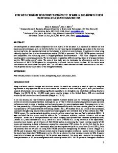
deformation, cracking in three orthogonal directions, and crushing. The element is defined by eight nodes having three translational degrees of freedom at each node. Link8 element is used to model steel reinforcement. It is a 3D spar element and has two nodes with three degrees of freedom – translations in the nodal x, y, and z directions at each node. This element is also capable of plastic deformation. Steel reinforcement is modeled with discrete representation technique (Tavarez, 2001), where reinforcement uses bar or beam elements that are connected to concrete mesh nodes as shown in Figure 1(b). Therefore, the concrete and the reinforcement mesh share the same nodes and concrete occupies the same regions occupied by the reinforcement.
(a)
(b)
Figure 1 (a) Dimensions of Reinforced Concrete Beam; (b) Discrete model technique The material properties for concrete considered are: compressive strength and tensile strength as 28.9 MPa and 2.9 MPa respectively; Density as 2435 kg/m3 and Modulus of elasticity as 27.7 GPa. While for the steel, yield strength considered as 505 MPa and density 7905 kg/m3, Modulus of elasticity as 205 GPa. The pin-roller boundary condition has been considered at the second bottom node from both ends of the beam.
(a)
(b)
(c)
(d) Figure 2 (a) light damage; (b) medium damage; (c) severe damage (d) The front elevation of a typical cracked beam In order to investigate the effects of damage locations and damage severities on the reinforced concrete beams, seven different damaged cases are employed in the numerical work. As observed in Figure 2, three types of severities: light, medium and severe are considered in terms of crack depths of 50, 100 and 150 mm. These cracks are imposed in turn at quarter span and midspan of the beam. All damage cases are described in Table 1. Table 1. Damage Scenarios considered in the present study Damage case
D0 D1 D2 D3 D4 D5
Location of Damage from left support Intact L/4 L/4 L/4 L/2 L/2
Crack Geometry
Natural Frequencies
Length (mm)
Depth (mm)
Width (mm)
Mode 1
Mode 2
Mode 3
--45 45 45 45 45
--50 100 150 50 100
--150 150 150 150 150
55.25 55.26 55.27 55.28 55.01 54.25
133.08 131.16 125.02 115.79 133.11 133.10
317.73 316.70 313.84 310.87 311.87 293.16
26
Civil and Environmental Research ISSN 2224-5790 (Paper) ISSN 2225-0514 (Online) Vol.3, No.13, 2013
D6 D7
L/2 L/4, L/2
45 45
www.iiste.org
150 150,150
150 150
53.33 53.28
133.02 114.26
264.96 252.78
4. Results and Discussions Simulated crack damage scenarios D1 to D6 represent the study at two locations namely, at L/4 and L/2, where L is the span of the beam. Modal analysis is repeated for each damage location and three natural frequencies and corresponding flexural mode shapes are obtained for the damaged beam. The modal flexibility change and modal curvature difference between the damaged and intact case are obtained by using a newly developed MATLAB code with modal data obtained from finite element analysis using ANSYS 12.0 as input. The curvature difference and modal flexibility change methods are used to locate the damage. The natural frequencies for the intact cases and typical damaged cases considered in the present study are listed in Table 1. The natural frequencies have been decreased with increase in the damage severity as compared to the undamaged case. However, from the changes in the natural frequencies existence of damage can be identified; its location cannot be predicted. The changes in the flexibility for typical damage locations are plotted in Figure 3 (a-c); Figure 4 (a-c) and Figure 5(a). Change in the flexibility matrix is zero at the supports and increases linearly towards the midspan of the beam. For each damage location, the change in flexibility reaches its maximum at the damaged element. Hence, for the beam, the region in which the change in the flexibility matrix is maximum is the damaged region. The change in the flexibility matrix is larger for the damages located at midspan of the beam than near the supports. The absolute differences between the curvature mode shapes of the intact and the damaged beam are plotted in Figure 3(d-f); Figure 4(d-f) and Figure 5(b). The maximum difference for each curvature mode shape occurs in the damaged region, the differences in the curvature mode shapes are localized near the damaged zone, i.e., it is much smaller outside the damaged region. The maximum difference for each of the damaged cases occurs in damaged zone. The maximum difference increases with reduction in stiffness (increase in crack depth) of the damaged zone. The higher modes give the better results. While predicting the crack damage for crack depth of 50 mm at all locations, flexibility method predicts false position in addition to the correct position as seen in Figure 3(a) and Figure 4(a). However, the correct location has been predicted with modal curvature method.
(a)
(b)
(c)
(d)
(e)
(f)
Figure 3 (a-c) Modal Flexibility Method (d-e) Modal Curvature Method for detection of damage at location L/4 (Damage Cases: D1 to D3)
27
Civil and Environmental Research ISSN 2224-5790 (Paper) ISSN 2225-0514 (Online) Vol.3, No.13, 2013
www.iiste.org
(b)
(a)
(c)
(d) (e) (f) Figure 4 (a-c) Modal Flexibility Method (d-e) Modal Curvature Method for detection of damage at location L/4 (Damage Cases: D4 to D6) Even for the multiple damage scenarios, both locations of the damage have been satisfactorily predicted by the modal curvature method as in Figure 5(b); while modal flexibility method resulted in false prediction of one location as shown in Figure 5(a).
(a)
(b)
Figure 5 (a) Modal Flexibility Method (b) Modal Curvature Method for detection of multiple damage scenario (Damage Case: D7) 5. Conclusions The methods of modal curvature and flexibility difference are applied to detect crack damage in Reinforced Concrete beam models. The numerical results demonstrate the effectiveness of both methods in locating single and multiple damage scenarios in RC beams. The modal curvature method can predict the exact location of crack for all damage scenarios; while modal flexibility method predicts false position in addition to the correct position for 50 mm crack depth. References Baghiee, N., Esfahani, M.R., & Moslem, K. (2009). “Studies on Damage and FRP Strengthening of Reinforced Concrete Beams by vibration monitoring”, Engineering Structures, 31, 875-893. Doebling, S.W., Farrar, C.R., & Prime, M. B. (1998). “A summary review of vibration-based damage identification methods”, Shock and Vibration Digest, 30, 91–105.
28
Civil and Environmental Research ISSN 2224-5790 (Paper) ISSN 2225-0514 (Online) Vol.3, No.13, 2013
www.iiste.org
Fayyadh, M.M., & Abdul Razak, H., “Detection of damage location using mode shape deviation : Numerical study” (2011a). International Journal of the Physical Sciences, 6, 5688-5698. Fayyadh, M.M., Abdul Razak H., & Ismail Z. (2011b). “Combined modal parameters-based algorithm for damage identification in a beamlike structure: theoretical development and verification”, Archives of Civil and Mechanical Engineering, 11, 587-609. Ismail, Z., Abdul Razak, H. & Abdul Rahman, A.G. (2006). “Determination of damage location in RC beams using mode shape derivatives”, Engineering Structures, 28, 1566-1573. Ismail, Z., Abdul Razak, H., Ibrahim, Z., Abdul Rahman, & A.G., Pooi, A.H. (2001). “Detection of defects in Reinforced Concrete beams using modal data”, Proc. 19th International Modal Analysis Conference (IMAC XIX), Orlando, Florida, USA, 1358-1362. Maeck, J., Wahab, M.A., Peeters, B., Roeck, G.D., Visschere, J.D., Wilde W.P. Ndambi, J.M, & Vantomme, J. (2000). “Damage identification in reinforced concrete structures by dynamic stiffness determination”, Engineering Structures, 22, 1339-1349. Ndambi, J. M., Vantomme, J., & Harri, K. (2002). “Damage assessment in Reinforced Concrete beams using eigen frequencies and mode shape derivatives”, Engineering Structures, 24, 501-515. Owolabi, G.M., Swamidas, A.S.J., & Seshadri, R. (2003). “Crack Detection in Beams using Changes in Frequencies and amplitudes of frequency response functions”, Journal of Sound and Vibration, 265, 1-22. Pandey, A.K. & Biswas, M. (1994). “Damage detection in structures using changes in flexibility”, Journal of Sound and Vibration, 169, 3-17. Pandey, A.K., Biswas, M., & Samman, M.M. (1991). “Damage detection from changes in curvature mode shapes”, Journal of Sound and Vibration, 145, 321-332. Perera, R., Huerta, C., & Orquın, J.M. (2008). “Identification of damage in RC beams using indexes based on local modal stiffness”, Construction and Building Materials, 22, 1656-1667. Tavarez, F.A. (2001). “Simulation of behaviour of composite grid Reinforced Concrete beams using explicit finite element methods”, Master’s Thesis, University of Wisconsin-Madison, Madison, Wisconsin.
29
This academic article was published by The International Institute for Science, Technology and Education (IISTE). The IISTE is a pioneer in the Open Access Publishing service based in the U.S. and Europe. The aim of the institute is Accelerating Global Knowledge Sharing. More information about the publisher can be found in the IISTE’s homepage: http://www.iiste.org CALL FOR JOURNAL PAPERS The IISTE is currently hosting more than 30 peer-reviewed academic journals and collaborating with academic institutions around the world. There’s no deadline for submission. Prospective authors of IISTE journals can find the submission instruction on the following page: http://www.iiste.org/journals/ The IISTE editorial team promises to the review and publish all the qualified submissions in a fast manner. All the journals articles are available online to the readers all over the world without financial, legal, or technical barriers other than those inseparable from gaining access to the internet itself. Printed version of the journals is also available upon request of readers and authors. MORE RESOURCES Book publication information: http://www.iiste.org/book/ Recent conferences: http://www.iiste.org/conference/ IISTE Knowledge Sharing Partners EBSCO, Index Copernicus, Ulrich's Periodicals Directory, JournalTOCS, PKP Open Archives Harvester, Bielefeld Academic Search Engine, Elektronische Zeitschriftenbibliothek EZB, Open J-Gate, OCLC WorldCat, Universe Digtial Library , NewJour, Google Scholar