G, Professor in Mechanical Engineering is working at College ... Kumar.S is working as a Lecture in Well International College of ... Automotive Air Compressor.
International Journal of Engineering and Technology Vol. 1, No. 1, April, 2009 1793-8236
Mathematical Modeling of Water Cooled Automotive Air Compressor Venkatesan J, Nagarajan G, Seeniraj R.V and Kumar S
Abstract— Mathematical modeling is the process of designing a model of a real system and conducting experiments with it for the purpose of understanding the behaviour of the system. Mathematical simulation is widely used for investigating and designing the compressors. Investigation of the processes of reciprocating compressors using mathematical models is an effective tool by high development of computing technique, which enables complicated problems to be solved with a minimal number of simplifying assumptions. A considerable number of previous works has been done on the mathematical modeling and simulation. This paper presents a simplified and effective mathematical model for the estimation of reciprocating compressor performance using personal computers that can be easily handled. The developed model has been validated using the experimental results from the compressor with reed vale in the delivery side and ring valve in the suction side. The compressor is tested for different delivery pressures and different shaft speeds. The effect of parameters speed, discharge pressure on thermodynamic behaviour of compressor in working condition has been analyzed. The model can predict cylinder pressure, cylinder volume, cylinder temperature, valve lift and resultant torque at different crank angles and free air delivered and indicated power of the compressor. The predicted results using the developed mathematical model are very much comparable with the experimental results. Index Terms—Resultant torque, Indicated power, Peak pressure, FAD, Volumetric efficiency.
I. INTRODUCTION A reciprocating compressor consists of a crankshaft (driven either by a gas engine, electric motor, or turbine) attached to a connecting rod, which transfers the rotary motion of the crankshaft to the piston. The piston travels back and forth in a cylinder [1]. The piston acting within the cylinder then compresses the air contained within that cylinder. Air enters the cylinder through a suction valve at suction pressure and is compressed to reach the desired discharge pressure. When the air reaches the desired pressure, it is then discharged through a discharge valve. Desired discharge pressure can be reached through utilization of either a single or double acting Manuscript received: December 15, 2008. Venkatesan.J, Assistant Professor and Research Scholar is working with Sri Venkateswara College of Engineering, Pennalur, Sriperumbudur, Chennai – 602105, India. Nagarajan.G, Professor in Mechanical Engineering is working at College of Engineering, Anna University, Chennai – 600025, India. Seeniraj.R.V, Professor (Retired), College of Engineering, Anna University, Chennai – 600025, India. Kumar.S is working as a Lecture in Well International College of Engineering and Management, Muscat, Oman.
cylinder. In a double acting cylinder, compression takes place at both the head end and crank end of the cylinder. The cylinder can be designed to accommodate any pressure or capacity, thus making the reciprocating compressor the most popular in the automobile and gas industry. Building a mathematical model for any project may be a challenging, yet interesting, task. A thorough understanding of the underlying scientific concepts is necessary and a mentor with expertise in the project is invaluable [8]. It is also best to work as part of a team to provide more brainstorming power. In industry and engineering, it is common practice for a team of people to work together in building a model, with the individual team members bringing different areas of expertise to the project. Once the model has been developed and applied to the problem, the resulting model solution must be analyzed and checked for accuracy. It may require modifying the model for obtaining reasonable outcome. This refining process should continue until obtaining a model that agrees as closely as possible with the real world observation. II. MODEL FORMATION Modeling is based on the following thermodynamic equations [1], [4], [7], [8] Suction
dT mRT dV dms (CvT− RCvTs) − dQ = 0 mCv + + dt V dt dt dt (1) Compression and Expansion dT mRT dV mCv + dt V dt (2) Discharge
−
dQ dt
= 0
dT mRT dV dmd (RCvTd− CvT) − dQ = 0 mCv + + dt V dt dt dt (3) Governing equation for determining the instantaneous cylinder pressure
pv = 1+ RT
n
∑ Bi (T ) ρ i i =1
(4) Note: The second term in equation (4) is negligible for single stage reciprocating air compressors. Governing equation for determining mass flow
dmop dm dmi dmo = − −∑ dθ dθ dθ dθ Governing equation for determining working volume
- 50 -
(5)
International Journal of Engineering and Technology Vol. 1, No. 1, April, 2009 1793-8236
dV S n sin θ cos θ = ± F sin θ + dθ Z 1 − n 2 sin 2 θ (6) Resultant torque is calculated using
sin 2θ T = Fp r sin θ + 2 (lc / r ) 2 − sin 2 θ
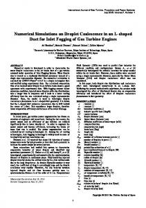
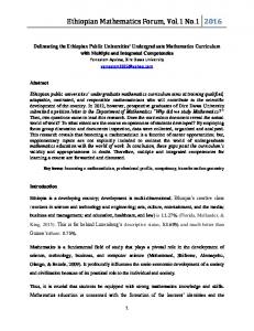
Delivery reed
Governor plate
F
(7)
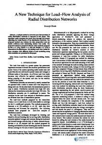
Indicated Power Since all the processes are not following particular thermodynamic law, it is not advisable to use readymade equation for finding out indicated power during suction or discharge process. The following general and effective model is used for estimating IP during any incremental crank angle [1]:
F
xd Fd Fig. 3 Delivery reed in full open position
p + p N IPθ = IPθ −1 + (Vθ −1 −Vθ ) θ −1 θ 2 60 (8) pθ-1 pθ
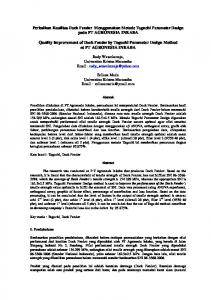
Fig.4 Ring type suction valve assembly
Vθ-1 Vθ
Where,
Fig. 1 Integration method of estimating Indicated Power
2 2 2 ω ω + 2ξ J s = 1 − ω ns ω ns
Deflection of delivery reed is calculated from [6],
Sd =
Fd x d3 (l d − x d ) (4 l d − x d ) 12 E I d l d3
(9)
(11)
III. EXPERIMENTAL DETAILS
2.2 Suction process [2], [3], [5]
F − Fsi S s = s ks J s
(10)
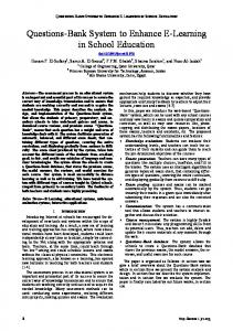
2.1 Discharge Process Delivery reed
Valve plate
Governor plate
F
F
Fig. 2 Delivery reed in closed position Fig. 5 Experimental Set up
The compressor with reed valve used in braking system of heavy passenger vehicles and trucks is tested using sophisticated test rig. The compressor is run by an electric motor. The pressure inside the cylinder is captured by Piezo-electric pressure transducer and the data is stored using Data acquisition system. The compressor speed is controlled - 51 -
International Journal of Engineering and Technology Vol. 1, No. 1, April, 2009 1793-8236
by a speed pot in the control panel. The compressor is cooled by a fan. The compressor is connected with 50 lit reservoir and the pressure is maintained by using the governor valve. IV. COMPRESSOR DETAILS The compressor under test is a single cylinder, single stage, water cooled reciprocating air compressor with swept volume of 230 cc. Ring type of valve is used in the suction side and reed valve is used in the delivery side. There are two circular ports of 11 mm diameter in the delivery side and 12 circular ports of 6 mm diameter in the suction side. Bore diameter (D) = 80 mm Crank radius (r)
= 23 mm
Connecting rod length (lc)
= 70 mm
Suction reed lift (hs)
= 2.2 mm
Delivery reed lift (hd)
= 1.8 mm
Mass of reciprocating parts (mrec)
= 0.347 kg
Clearance volume (Vc)
= 8 cc
Discharge pressure (pd)
= 6 to 9 bar (abs)
Compressor speed (N)
= 600 to 3000 rpm
Diameter of suction port (dos)
= 6 mm
Diameter of delivery port (dod)
= 11 mm
Distance (xs)
= 59 mm
Distance (xd)
= 26.5 mm
Effective length of delivery reed (ld) = 45.5 mm Mass of suction valve (ms)
=3g
Mass of delivery valve (md)
=2g
Number of suction ports (Zs)
= 12
Number of delivery ports (Zd)
=2
pressure are constant. This is due to the assumption that the cylinder diameter is equal to suction /discharge port diameter. In actual compressor the port diameter will be less than the cylinder diameter. Therefore during suction process the volume displaced by piston will be greater than the air entering the cylinder during particular time interval. The net effect is the decrease in suction pressure below that of an ideal compressor. Similarly during discharge process the volume displaced by the piston will be greater than the volume of air discharged through discharge port. The net effect is the increase in cylinder pressure above discharge pressure. Due to excess peak pressure during discharge process, the indicated power of the compressor is always greater than the ideal indicated power for particular FAD. The volumetric efficiency is mainly dependent on the suction pressure. The effect of reduced suction pressure is to reduce the volumetric efficiency significantly. The model has been tested with different discharge pressures and compressor speeds. Table 1, Table 2 and Table 3 give the performance parameters of compressor at shaft speed of 3000 rpm, 1800 rpm and 600 rpm respectively. The corresponding characteristic curves for 3000 rpm and 1800 rpm are shown in Fig.6 to Fig.19. The simulated results found to be very close to the experimental results which ensure the accuracy of the model. It can be observed from Pressure-Crank angle and Pressure-Volume diagrams (Fig.6 to Fig.9) that the cylinder pressure during suction is less than atmospheric pressure and during discharge is greater than the discharge pressure. This is due to fluttering of suction valve and discharge valve during suction and discharge. The variation of valve lift and resultant torque with crank angle is shown in Fig.10 to Fig13 for the compressor speed of 3000 rpm and 1800 rpm. The variation of Free Air Delivered, Volumetric efficiency and Shaft power is shown in Fig.14 to Fig.22 to validate the developed model.
V. RESULTS AND DISCUSSIONS In ideal compressor, the suction pressure and discharge TABLE 1 PERFORMANCE OF COMPRESSOR AT DIFFERENT DISCHARGE PRESSURES (N = 3000 RPM)
Results ↓
6 bar Pre
6 bar Exp
7 bar Pre
7 bar Exp
8 bar Pre
8 bar Exp
9 bar Pre
9 bar Exp
Peak Pressure (bar)
11.84
11.38
12.73
12.63
13.49
13.05
14.43
14.71
Free Air Delivered (lpm)
438.2
458
428.4
441
416.0
426.4
406.2
404.3
Volumetric Efficiency (%)
63.2
66.4
61.8
63.9
60.0
61.8
58.6
58.6
Shaft Power (W)
3.8
3.52
4.0
3.52
4.2
3.59
4.3
3.63
TABLE 2 PERFORMANCE OF COMPRESSOR AT DIFFERENT DISCHARGE PRESSURES (N = 1800 RPM)
Results ↓
6 bar Pre
6 bar Exp
7 bar Pre
7 bar Exp
- 52 -
8 bar Pre
8 bar Exp
9 bar Pre
9 bar Exp
International Journal of Engineering and Technology Vol. 1, No. 1, April, 2009 1793-8236
Peak Pressure (bar)
9.08
7.98
9.70
9.50
10.36
10.57
11.43
11.58
Free Air Delivered (lpm)
308.5
306.4
300.1
296
288.3
284.5
281.8
277.4
Volumetric Efficiency (%)
74.1
74.0
72.1
71.5
69.3
68.7
67.7
67.0
Shaft Power (W)
1.9
2.04
1.9
2.09
2.0
2.21
2.1
2.21
TABLE 3 PERFORMANCE OF COMPRESSOR AT DIFFERENT DISCHARGE PRESSURES (N = 600 RPM)
Results ↓ Peak Pressure (bar) Free Air Delivered (lpm) Volumetric Efficiency (%) Shaft Power (kW)
6 bar Pre
6 bar Exp
7 bar Pre
7 bar Exp
8 bar Pre
8 bar Exp
9 bar Pre
9 bar Exp
7.11
7.00
8.22
7.98
9.47
9.02
10.54
10.06
95.5
96.9
88.1
92.1
87.5
87.3
90.4
82.2
68.8
70.2
63.5
66.7
63.1
63.2
65.1
59.5
0.47
0.55
0.49
0.62
0.52
0.64
0.54
0.65
16
16
14
Pressure (bar)
Pre s s ure (ba r)
14 12 10 8 6
12 10 8 6 4
4
2
2
0 0
0 0
30
60
30
60
90
90 120 150 180 210 240 270 300 330 360
Predicted
Crank Angle (deg) Predicted
120
150
180
210
240
Volume (cc) Experimental
Fig.8 Pressure-Volume diagram (Discharge pressure = 9 bar, Speed = 3000 rpm)
Experimental
Fig.6 Pressure-Crank angle diagram (Discharge pressure = 9 bar, Speed = 3000 rpm)
14
Pressure (bar)
12
14
Pressure (bar)
12 10
10 8 6 4
8 2
6 0
4
0
2
30
60
90
120
150
180
210
240
Volume (cc)
0
Predicted 0
30
60
Experimental
90 120 150 180 210 240 270 300 330 360
Fig.9 Pressure-Volume diagram (Discharge pressure = 9 bar, Speed = 1800 rpm)
Crank Angle (deg) Predicted
Experimental
Fig.7 Pressure-Crank angle diagram (Discharge pressure = 9 bar, Speed = 1800 rpm)
53
International Journal of Engineering and Technology Vol. 1, No. 1, April, 2009 1793-8236
Free Air Delivered (lpm)
2
Valve Lift (mm)
1.8 1.6 1.4 1.2 1 0.8 0.6 0.4
500 450 400 350 300 250 200
0.2
5
0 0
30
60
90
120
150
180
210
240
270
300
330
6
360
7
8
9
10
Discharge Pressure (bar)
Crank Angle (deg) Predicted
Predicted
Fig.14 Free Air Delivered-Discharge Pressure diagram (Speed = 3000 rpm)
2 1.8
V a lv e Lift (m m )
350
Free Air Delivered (lpm)
Fig.10 Valve Lift-Crank Angle diagram (Discharge pressure = 9 bar, Speed = 3000 rpm)
Experimental
1.6 1.4 1.2 1 0.8 0.6
325 300 275 250
0.4
5
0.2 0 0
30
60
90
120
150
180
210
240
270
300
330
6
7
8
9
10
Discharge Pressure (bar)
360
Crank Angle (deg)
Predicted
Experimental
Predicted
Fig.11 Valve Lift-Crank Angle diagram (Discharge pressure = 9 bar, Speed = 1800 rpm)
Fig.15 Free Air Delivered-Discharge Pressure diagram (Speed = 1800 rpm)
Free Air Delivered (lpm)
R esultant Torque (Nm )
100 80 60 40 20
150 125 100 75 50
0 0
30
60
90
120
150
180
210
240
270
300
330
5
360
6
7
8
9
10
Discharge Pressure (bar)
-20
Crank Angle (deg) Predicted
Predicted
Fig.16 Free Air Delivered-Discharge Pressure diagram (Speed = 600 rpm)
Volumetric Efficiency (%)
Fig.12 Torque-Crank Angle diagram (Discharge pressure = 9 bar, Speed = 3000 rpm)
Resultant Torque (Nm)
100 80 60 40 20 0 0
30
60
90
120
150
180
210
240
270
300
330
Experimental
360
100 90 80 70 60 50
5
6
7
8
9
10
Discharge Pressure (bar)
-20
Crank Angle (deg)
Predicted
Predicted
Fig.13 Torque-Crank Angle diagram (Discharge pressure = 9 bar, Speed = 1800 rpm)
Experimental
Fig.17 Volumetric Efficiency -Discharge Pressure diagram (Speed = 3000 rpm)
- 54 -
Volumetric Efficiency (%)
International Journal of Engineering and Technology Vol. 1, No. 1, April, 2009 1793-8236
Shaft Power (kW)
80
70
60
5
6
7
8
9
10
1 0.8 0.6 0.4 0.2 0
5
Discharge Pressure (bar) Predicted
Experimental
Predicted
Volumetric Efficiency (%)
75 70 65 60 55 50
5
6
7
8
9
10
Experimental
Fig.19 Volumetric Efficiency -Discharge Pressure diagram (Speed = 600 rpm)
10 8 6 4 2 0
6
7
8
9
10
Discharge Pressure (bar) Predicted
10
Experimental
Experimental
The developed model predicts fluctuation of pressure during suction and discharge processes. It predicts valve fluttering during suction and discharge at all delivery pressures. The fluttering increases with decrease of compressor speed. The simulated results from the model are very much comparable with the experimental results. It is possible to get Volumetric efficiency, Free air delivered, Indicated power, Cylinder air pressure, Cylinder air temperature, Resultant torque and Mass of air sucked-in or discharged out per cycle, by varying any operating parameters like, speed, discharge pressure, etc., and physical parameters like, clearance volume, crank radius, connecting rod length and cylinder diameter. The developed simulation model can be used for theoretical analysis of single stage, single cylinder reciprocating air compressor with disc valve. The development of model is based on the previous works and technical resources in the compressor field. The constants used in the development of model are based on the available experimental results and information from previous work in the compressor design field. Simple assumptions are made in the development of model which can be varied or omitted depending on the operating and physical conditions of the compressor. The effectiveness of the developed model is very much dependent on the “usage of suitable constants” in the model like, coefficient of discharge, index of compression, etc.
Fig.20 Shaft Power-Discharge Pressure diagram (Speed = 3000 rpm) 5
NOMENCLATURE
T
– Temperature
lc
– Length of connecting rod
r
– Crank radius
1
θ
– Crank angle
0
ω
– Angular velocity of the crank
N
– Compressor speed
p
– Pressure
V
– Volume
Z
– Number of ports
E
– Young’s modulus of valve material
I
– Area moment of inertia of valve
4 3 2
5
9
VI. CONCLUSION
Predicted
Shaft Power (kW)
8
Fig.22 Shaft Power-Discharge Pressure diagram (Speed = 600 rpm)
80
Discharge Pressure (bar)
Shaft Power (kW)
7
Discharge Pressure (bar)
Fig.18 Volumetric Efficiency -Discharge Pressure diagram (Speed = 1800 rpm)
5
6
6
7
8
9
10
Discharge Pressure (bar) Predicted
Experimental
Fig.21 Shaft Power-Discharge Pressure diagram (Speed = 1800 rpm)
- 55 -
International Journal of Engineering and Technology Vol. 1, No. 1, April, 2009 1793-8236
– Distance of point of application of force from
xd
Authors Details
fixed end Cv
– Specific heat at constant pressure
m
– Mass of air in the cylinder
ms
– Mass of air flowing through the suction valve
md
– Mass of air discharged out through the delivery
1. Venkatesan.J Assistant Professor & Research Scholar Department of Mechanical Engineering Sri Venkateswara College of Engineering Sriperumbudur, Chennai, India 2. Dr. Nagarajan.G Professor Department of Mechanical Engineering College of Engineering, Anna University Chennai, India
valve S
– Valve lift
n
– Ratio of connecting rod length to cylinder diameter
Fp
– Net force acting on the piston
Fsi
– Force due to initial compression of valve
ωn
– Natural frequency of valve
ς
– Damping factor
m
– Instantaneous mass
Q
– Heat transfer to actuating medium
α(θ)
– Heat transfer coefficient
Exp
– Experimental
Pre
– Predicted
4. Kumar.S Lecturer Well International College of Engineering and Management Muscat, Oman Corresponding Author Venkatesan.J Assistant Professor & Research Scholar Department of Mechanical Engineering Sri Venkateswara College of Engineering Sriperumbudur – 603 105, Chennai, India
lpm – Lit per minute Subscripts s – Suction
d – Delivery e – Effective REFERENCES [1]
[2]
[3]
[4]
[5]
[6] [7]
[8]
3. Dr. Seeniraj.R.V Professor (Retired), Anna University Chennai, India
Venkatesan J, Nagarajan G, Seeniraj R.V and Sampath S (2007) ”Mathematical Model for Theoretical Investigation of a Disc Valve Reciprocating Air Compressor of Automotive Braking System”, International Journal of Applied Mathematical Analysis and Applications, Volume 2, No. 1-2, pp. 209-227, Serial Publications, New Delhi, India. Werner Soedel (1980)– ”Design and Mechanics of Compressor Valves”, Ray.W.Herrick Laboratories, School of Mechanical Engineering, Purdue University, West Lafayette, Indiana, USA. Arne.M.Bredesen (1974) – “Computer Simulation of Valve Dynamics as an Aid to Design”, Norwegian Institute of Technology – Proceedings of International Conference on Compressor Technology, Purdue University, West Lafayette, Indiana, USA. Kazutaka Suefuji, Susuma Nakayama (1980) – “Practical Method for Analysis and Estimation of Reciprocating Hermetic Compressor Performance”, Hitachi Ltd, Japan – Proceedings of International Conference on Compressor Technology, Purdue University, West Lafayette, Indiana, USA. Stif Helmer Joergensen, Danfoss, Nordborg (1980) – “Transient Valve Plate Vibrations” – Proceedings of International Conference on Compressor Technology, Purdue University, West Lafayette, Indiana, USA. Francis Tse et all (1965) – “Mechanical Vibrations”, CBS distributors, Delhi. S.Lawson and R.J.L.McLaren (1984) – “An Approach to Computer Modeling of Reciprocating Compressors”, Prestoold Limited, U.K, Proceedings of the 1984 Purdue Compressor Technology Conference, Purdue University, West Lafayette, Indiana, USA. C.Tian, Y.Liao, X.Li (2005) – “A Mathematical model of variable displacement swash plate compressor for automotive air conditioning system”, International Journal of Refrigeration, Volume 29, Issue 2, Pages 270-280.
- 56 -