Tex database. For test images which are most different from the training images (different instances of the same texture observed, non-equal illumination slants), ...
O. Drbohlav and M. J. Chantler: Illumination-invariant texture classification using single training images. In Texture 2005: Proceedings of the 4th International Workshop on Texture Analysis and Synthesis, pp. 31–36, 2005.
Illumination-Invariant Texture Classification Using Single Training Images Ondrej Drbohlav and Mike Chantler Texture Lab, School of Mathematical and Computer Sciences Heriot-Watt University Edinburgh, UK
Abstract The appearance of a surface texture is highly dependent on illumination. This is why current surface texture classification methods require multiple training images captured under a variety of illumination conditions for each class. We show that a single training image per class can be sufficient if the surfaces are of uniform albedo and smooth and shallow relief, and the illumination is sufficiently far from the texture macro-normal. The performance of our approach is demonstrated on classification of 20 textures in the PhoTex database. For test images which are most different from the training images (different instances of the same texture observed, non-equal illumination slants), the success rate achieved is in the range of 60–80%. When the test images differ from the training ones only in illumination tilt, the success rate achieved is well above 95%.
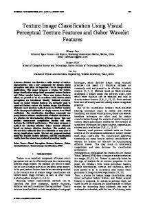
1. Introduction Appearance of textures possessing a three-dimensional relief strongly depends on illumination. While all state-of-art methods dealing with illumination-invariant texture classification need multiple training images per class, the central question posed in this article is: Does there exist a method for illumination-insensitive comparison of two images of a texture captured under different illumination conditions? Under the assumptions summarised in the Abstract, this paper shows that the answer to this question can be positive, and i) presents a theory which shows that two images of a surface can be made virtually identical by filtering each of the images by a linear filter corresponding to a directional derivative. The filters are generally different for each of the two images, and depend on the illumination directions used (see Fig. 1), ii) implements a method which employs this theory to establish the similarity measure of a pair of texture images captured under two unknown illumination directions, and
-
-
Figure 1: Basic idea of our approach: When images illuminated from two different directions (indicated by white arrows) are filtered by a directional derivative in reciprocal directions (grey arrows) and properly scaled, they can look almost identical. ‘Reciprocal’ means that projected light direction of the first image is used to filter the second image, and vice versa. iii) employs this method for illumination-invariant texture classification with a single training image per class. The classification is based on simply computing the distances of a query image to each of the class exemplar images, and choosing the one which is the closest. To the best of our knowledge, this paper is the first which, albeit under assumptions which might look at a first sight restrictive, solves the problem of illuminationinvariant two-image texture comparison. While such a problem is indeed interesting on its own, it is motivated by practical considerations. For example, for retrieval from unstructured databases, image-by-image comparison of a query image with the database images has to be performed. By unstructured, we mean that the database does not necessarily contain images that are representative set for a wide range of illumination conditions for a given material. The central question we address is naturally related to the topic of illumination invariants and previous work on two-image comparison under different illumination. Chen,
Belhumeur and Jacobs [4] used joint probability of image PSfrag replacements gradient directions to compute the likelihood that two imn z ages come from the same surface; Jacobs, Belhumeur and l θ i Basri [7] exploited the fact that the ratio of the twoPSfrag imagesreplacements l θ is varying slower when they are produced from the same surface than if they come from two different objects. Howy φ ever, these approaches rely on joint, inter-image features ˆl which require the images to be spatially registered (or at x least, spatially registerable). They are thus not easily ex(a) (b) tendable for comparing two texture images, as these usually come from two different instances (surface portions) which, Figure 2: (a) Reflectance geometry: the angle of incidence for the same texture, share only the texture statistics but not θi . (b) Slant and tilt of a light source l: slant θ is the angle the geometry. between the camera axis and l. Tilt φ is the angle between Recent work of Osadchy, Lindenbaum and Jacobs [9] the x-axis and the projected light ˆl. achieves illumination quasi-invariance on smooth surfaces using the whitening approach. The assumptions are that the surface is Lambertian, of uniform reflectance, and of shalAll these previous approaches need multiple training imlow relief and that the illumination direction is sufficiently ages per class. Our classification method requires a sininclined from the surface macro-normal. The method is apgle training image per class, and is implemented by simply plied for classification of registered images of smooth obcomputing the distances of the query image to all training jects. It is not easily extendable for texture recognition eiimages, and then selecting the class of the one which is the ther, as its effect increases the dissimilarity between images closest. coming from different objects, as opposed to making the images produced by the same surface more similar [9]. 2. Theory Our method is fundamentally different from previous In this Section, we show that two images of the same surface work in that it can make the two images of the same surface captured under different light directions can be made virtuvirtually identical. We therefore hypothesise that it can also ally identical. This is achieved by filtering each of them match the image statistics of the same surface texture obby a derivative filter which depends on the light used for served under different illumination conditions, and we imcapturing the other image. The assumptions needed for deplement a method for such two-image texture comparison. veloping the theory are that the surface is smooth, of uniWe employ our two-image comparison approach for texform Lambertian reflectance and shallow relief, and that the ture classification problem. Previous work in the area illumination is sufficiently inclined from the surface macroof texture classification under varying illumination can be normal. roughly divided into two groups: The way we proceed is as follows. First, we review what i) Appearance-based approaches need a representative set the link is between the image gradient and the surface difof examples captured under varying illumination. This apferential properties (similar derivation can be found in [4]). proach includes Leung and Malik [8], Varma and Zisserman This comprises Eqs. (1)—(6), and is a pre-requisite for the [10] or Cula and Dana [5]. The methodology in this group principal observation made in the rest of this Section. is that the textons are obtained first from the training data by Notations and definitions. Partial derivatives of a function clustering in a high-dimensional space, and their histograms def f are denoted by a letter subscript (fx = ∂f /∂x). The graare then used as features. For assessing the proximity of dient of f is denoted ∇f . A directional derivative of f with features, a χ2 -test is used. respect to a vector u ∈ R2 is denoted by a vector subscript ii) Model-based approaches are called so in this paper as (fu ) and its relation to gradient is fu = u · ∇f . Vector u is called directional derivative vector. The camera is assumed they employ the illumination model. These are represented to be orthographic with square pixels, and the global coordiby works of Chantler et al [3] or Barsky [2]. Chantler et nate system to have its z-axis vertical and aligned with the al show that the response of variance of a filtered image is camera optical axis. The slant and tilt of illumination disinusoidal under varying illumination tilt. Barsky [2] comrection are defined as the polar and azimuth angle in usual putes statistical surface descriptors from data obtained by spherical coordinates (see Fig. 2(b)). Any surface geomphotometric stereo, and generalises Chantler’s approach to etry is assumed to be representable by a height function non-uniform albedo materials and general light directions. z = z(x, y). This function is assumed to be C2 continuBoth these works use variance of images filtered by linear operators as features. ous, implying that zxy = zyx . And finally, having a vector
ˆ ∈ R2 represents the projecx ∈ R3 , a projected vector x tion of such vector onto the plane x − y (see Fig. 2(b) for an example given by projected light vector ˆl). For Lambertian surfaces, the surface reflectance at a surface patch is characterised by albedo which represents the amount of light which is scattered from the surface back into the air and is denoted ρ. The intensity i at a pixel observing the patch is then i = ρσ cos θi ,
(1)
where θi is the angle of incidence (see Fig. 2(a)) and σ is the light source intensity. In this article, we assume uniform albedo surfaces, and without loss of generality we set ρ = 1. The above equation can then be rewritten as T
i = σlT n = (σl) n = sT n ,
(2)
where l and n are the unit light and normal vectors, respectively, and the vector s = σl is called the scaled p light. ExT pressing the normal as n = (−p, −q, 1) / 1 + p2 + q 2 with p = zx , q = zy being the surface height gradient [6], gives T (−p, −q, 1) . i = sT p (3) 1 + p2 + q 2 The derivative of image intensity with respect to x is T
ix
T
=
−ˆsT (px , qx ) 1 sT (−p, −q, 1) p − p (2�ppx + 2 �qqx ) 2� 1 + p2 + q 2 3 1 + p2 + q 2
=
−ˆsT (px , qx ) −ˆ nT (px , qx ) p −i p 1 + p2 + q 2 1 + p2 + q 2
T
T
(4)
ˆ is the projected where ˆs is the projected light vectorpand n ˆ = (−p, −q)T / (1 + p2 + q 2 ). The surface normal n other component of intensity gradient is, similarly, T
T
−ˆsT (py , qy ) −ˆ nT (py , qy ) p (5) − ip . 1 + p2 + q 2 1 + p2 + q 2 � � px q x Denoting H = the surface height Hessian, the py q y image intensity gradient ∇i can thus be written briefly as iy
Figure 3: An example of filtering two images of the same texture AAJ (first two images) by reciprocal projected light directions. The match of the filtered images (last two images) is excellent, despite great perceptual difference of raw images. The slants of the two images are 45◦ and 60◦ , respectively, and the tilts are 30◦ and 330◦ , respectively. The raw images are scaled for display purposes. We observe that making the directional derivative of the first image with respect to ˆt and of the second image with respect to ˆs gives ˜ s + iˆtT Hˆ ˜n, ˆ t · ∇i = −ˆtT Hˆ T ˜ˆ T ˜ ˆ s · ∇j = −ˆs Ht + jˆs Hˆ n.
(8) (9)
˜ ˆt) are equal for both ˜ s and −ˆsT H The first terms (−ˆtT Hˆ images because the Hessian is symmetric due to C2 surface continuity (implying py = qx ). The second terms are generally different. If the result of filtering is required to give similar images, the second terms must be small compared with ˜ n|). ˜ n)|, |jˆsT Hˆ ˜ s| � max(|iˆtT Hˆ the first terms, i.e. |ˆtT Hˆ The general necessary conditions for these inequalities to hold are the following: a) Shallow relief. The projected normal should be of small length (kˆ n � 1k) which scales down the magnitude of the terms which are required to be small. b) Non-vertical illumination. This is an obvious necessity as if, say, s is vertical then ˆs = 0 and the symmet˜ s would vanish. ric term ˆtT Hˆ
=
H
˜ s + iˆ (−ˆs + iˆ n) = H(−ˆ n) , (6) 1 + p2 + q 2 p ˜ = H/ 1 + p2 + q 2 is the local surface Hessian where H scaled by the denominator term. We now consider two images i and j of a surface, one illuminated with light s and the other with light t. The respective image gradients are, according to Eq. (6) ∇i = p
˜ s + iˆ ∇i = H(−ˆ n) ,
˜ ˆt + j n ˆ) . ∇j = H(−
(7)
These conditions are necessary but not sufficient because ˜ s can still vanish for special configurations of the two ˆtT Hˆ ˜ As an example, conlights and the Hessian matrix H. sider the case when the Hessian is a scaled identity matrix and the two projected light directions are perpendicular to ˜ s is zero. each other. In such case, the symmetric term ˆtT Hˆ Whether this represents a problem or not depends on the geometry of the surface imaged. The magnitude of the second terms is constrained by the two conditions, and thus even several points within the image in which the first term has large magnitude should be sufficient to guarantee that the images look very similar. This theory is illustrated in Figs. 1 and 3. Fig. 1 shows real images of a wallpaper (class ACD in PhoTex [1]) which is illuminated from directions indicated by a white arrow (with slants being 45 and 60 degrees, respectively). The
(u · ∇) -
6 (a)
compute variance-
f1
-
f2
-
f3
-
f4
-
f5
filter bank-
6 (b)
6 (c)
L2 normalise
- F(u)
6 (d)
Figure 5: Given the derivative filter vector u, the feature vector F(u) is constructed as follows. The image is filtered first (a), and the filter bank is applied subsequently (b). Variances of the filtered images are computed and are concatenated to form a vector (c). Subsequently, this vector is L2 normalised (d). Note that this figure shows one scale only; in our implementation, the processing is done on 3 octaves, and the resulting feature vector is thus 15-dimensional. compare the resulting feature vectors using Euclidean distance which gives the measure of similarity. Figure 4: The filter bank used in our experiments. The first four filters are high-frequency odd Gabor filters at four orientations. The last filter is a Gaussian. All filters have σ = 1.4pixels. images are then shown filtered in reciprocal projected light directions and variance-normalised. Fig. 3 shows another example, for class AAJ. The filtered images show a very good match.
3. Algorithms and Methods The previous section showed that two images can be made virtually identical by filtering them in reciprocal projected light directions. This observation can be applied to twoimage texture comparison. While two surface texture images captured under different illumination conditions have different statistics, our approach suggests that the filtered images will have similar statistics. The examples shown in Figs 1 and 3 support this hypothesis. Known illumination conditions. In order to measure the similarity of two surface textures imaged under known illumination conditions, we apply the approach outlined in Fig. 5 to each of the images1 . For a given image, let the projected light of the other image be u. We first filter by a directional derivative operator (u · ∇) and then compute the set of texture features. For our experiments, we have used Gabors simply because they are popular in the literature (see Fig. 4). Subsequently, we apply the usual non-linear step consisting of taking the variance of filtered images, and we 1 Disregard
the L2 normalisation as this stage is only required later.
Unknown illumination conditions. Under unknown illumination conditions, the two derivative filter vectors must be estimated. We remove the dependencies on their magnitudes by normalising with respect to variance. What remains therefore is to search through the possible tilt directions of the illuminants. We use an exhaustive search on a small number of tilt directions. The implementation details are as follows. For texture features we use 5 Gabors on 3 octaves, thus the feature vectors are 15 dimensional. Statistics of each image is represented by feature vectors computed for 9 tilts (0◦ to 160◦ with2 a step of 20◦ ). To evaluate the distance of two images, we find the closest pair of feature vectors, which involves 9 × 9 = 81 comparisons of 15-dimensional vectors. Texture classification with single training images. Having a single training image per class, texture classification is achieved by computing the distance of a query image to each of the training images. This is done using the twoimage texture comparison under unknown illumination conditions. Subsequently, the class is selected according to which of the training images is closest to the query image.
4. Experiments All tests were carried out on the PhoTex database [1]. The core of this database is formed by images of surface textures which are held fixed and are observed from a constant viewpoint for different illumination directions. The light slants are 30◦ ,45◦ ,60◦ and 75◦ . The light tilts are φ = {0◦ , 30◦ , . . . , 300◦ , 330◦ } for slants in the set θA = {45◦ , 60◦ , 75◦ }, and φ = {0◦ , 90◦ , 180◦ , 360◦ } for slant 2 Note that sampling the tilt in a range of 180◦ is indeed sufficient, as opposite derivative directions give rise to the same feature vectors.
��, 45, 45 first correct correct within first 3 1–AAA
6–AAO
2–AAB
7–AAR
3–AAJ
8–AAS
4–AAM
9–ABA
our 81.2 95.8
Barsky[2] 85.2 98.2
5–AAN
10–ABJ
11–ABK
12–ACC
13–ACD
14–ACE
15–ADB
16–ADC
17–ADD
18–ADE
19–ADG
20–ADH
Figure 6: PhoTex classes used in the classification experiment. The images shown correspond to illumination slant θ = 60◦ and illumination tilt φ = 0◦ . θB = 30◦ . In this article, we work only with set θA because set θB contains too few images. We selected 20 textures to work with (see Fig. 6); we considered the same set of textures as Barsky did in [2] to allow for comparison of classification performance with this reference. Images in the database were all divided to two halves (left and right). Classification experiments were carried out both for the case when the training and test images from the same half were employed (this meant that the same portion of surface, although under different illumination, was involved while comparing the query image with its native class training image) and for the case when they were from different halves. Each classification experiment setting consisted of three entities: 1. Surface portions used A binary parameter which says whether the same halves of database images were used (will be denoted ��) in an experiment, or not (denoted ��). Note that if the same halves were used this did not mean the overlap of training and test sets because test set was always different at least in illumination conditions3 . 2. Slant of the training images The tilt was 30◦ and slant was 45◦ in all cases. The choice of slant is motivated by i) eliminating the extent of shadows, and by ii) the intention to test the ability of our method to generalise for slants which are distant from the training slant; testing on slant 75◦ gives 30◦ difference. 3 If the same halves were used and the training and test images were produced under the same illumination slant, the images corresponding to training tilt were removed from the test set.
Table 1: Comparison of performance with the method of Barsky [2]. First row lists the basic classification rates, while the second row lists the rate for a case when ‘correct class within first three retrieved’ is considered a success. Experimental settingsa
our approach
Laplace
k∇k
no filtering
��, 45, 45 ��, 45, 60 ��, 45, 75 ��, 45, 45 ��, 45, 60 ��, 45, 75
97.3 94.5 61.8 81.2 81.2 67.5
53.6 52.3 45.5 52.5 50.4 46.2
46.8 40.5 27.7 45.8 38.8 27.1
59.5 53.6 40.5 45.8 49.6 37.5
a Experimental settings read: ��, 45, 45 = the surface portions in training/testing sets were the same, and slant for both was 45◦ . ��, 45, 60 = the surface portions for training/testing were different, slant for training images was 45◦ and slant for test images was 60◦ .
Table 2: Classification success (in percent) for different experimental settings (rows) and different methods employed for classification (columns). The performance of our approach (first column), was compared with three naive approaches (other columns) in which filtering by directional derivative (step (a) in Fig. 5) is replaced by a directionless operator indicated.
3. Slant of the test images The slant was always one of {45◦ , 60◦ , 75◦ } and all (twelve) tilts in the database were used. The algorithm employed for classification was as described in the previous section. The experiments for various experimental settings produced promising results (see column ’our approach’) in Tab. 2. For the case when the slants and the surface portions used for training and testing were the same, the recognition rate was 97.3%. When different surface portions were used, the rate decreased to 81.2%. As expected, the rate also drops with increasing difference between the training and test slants. Comparison with other approaches. We have compared our approach with one model-based approach due to Barsky [2] and we have also compared our method with three naive approaches. In Tab. 1 we show the comparison with the classification result given by Barsky’s model-based approach [2]. Our approach is only slightly inferior, despite the fact that we classify using only one training image, while the work described in [2] needs at least three registered training images to employ photometric stereo at the first step of the algo-
rithm. The comparison is fair, but still it should be considered just approximate because Barsky used different filters to extract features, and divided the surface into quarters, learning from one, and testing on the other three. The naive approaches we used were: i) removing the directional derivative (step (a) in Fig. 5), ii) replacing the directional derivative by a directionless magnitude-ofgradient operator, and iii) replacing the directional derivative by the (directionless) Laplacian operator. In all three cases, we did not otherwise change the specification of the filter banks. Table 2 shows that the three approaches perform better than random choice (5%). However, their performance falls far short of the results produced by our approach. Misclassifications. We investigated the misclassifications produced by our approach4 , and discovered that they were basically of three types. The first cause of misclassification was that some classes (e.g. AAM, AAN, AAO) were perceptually close together. The second major cause of misclassification was the presence of shadows which, after being filtered, wipe out large areas of images. The third misclassification type was observed when filtered images of the correct class were perceptually similar, and yet the features we used ranked other candidates higher. We believe that this type of error could be removed by using more sophisticated features (e.g. [10]).
5. Summary, and Conclusions This paper has shown that, subject to certain assumptions, it is possible to make two images of a surface observed under two different illuminations very similar. We have implemented a method which exploits this fact and enables us to compare two textured surfaces illuminated under unknown illumination conditions. The usability of the method was demonstrated on a texture classification problem with single training images per class. The experiments showed that the performance of our approach which employs directional derivatives is considerably better than naive approaches based on (directionless) Laplacian, magnitude of gradient, or no filtering at all. The price paid for the high performance of our method is more computational expense, requiring optimisation of both directions of the derivatives applied to the images. A comparison with a model-based approach due to Barsky [2] suggests that our method performs comparably on the PhoTex database, despite that fact that it employs single training images. The advantage of the method described in [2] is that it does not require the assumptions we make 4 We wrote a tool to export the results of a classification experiment into HTML where all test images can be viewed along with their filtered versions and classification statistics. Such exports enable to easily review the performance and hypothesise the causes of misclassifications
about the surface nor about the light sources; but needs three registered training images per class at least.
Acknowledgements O. Drbohlav is supported by the Marie Curie IntraEuropean Fellowship No. 506053 (PhoCal) within the 6th European Community Framework Programme. M. Chantler acknowledges the support by EPSRC grant GR/S12395/01.
References [1] PhoTex database. Texture lab, Heriot-Watt University, Edinburgh, UK. Available on-line at http://www.cee.hw. ac.uk/texturelab/database/photex/. [2] S. Barsky. Surface Shape and Colour Reconstruction using Photometric Stereo. PhD thesis, University of Surrey, Oct. 2003. [3] M. Chantler, M. Schmidt, M. Petrou, and G. McGunnigle. The effect of illuminant rotation on texture filters: Lissajous’s ellipses. In Proc. European Conference on Computer Vision, volume 3, pages 289–303, 2002. [4] H. Chen, P. Belhumeur, and D. Jacobs. In search of illumination invariants. In Proc. IEEE Conference on Computer Vision and Pattern Recognition, volume 2, pages 254–261, 2000. [5] O. G. Cula and K. J. Dana. 3D texture recognition using bidirectional feature histograms. International Journal of Computer Vision, 59(1):33–60, 2004. [6] B. K. P. Horn and M. J. Brooks. Shape from shading. The MIT Press, 1989. [7] D. W. Jacobs, P. N. Belhumeur, and R. Basri. Comparing images under variable illumination. In Proc. IEEE Conference on Computer Vision and Pattern Recognition, pages 610– 617, 1998. [8] T. Leung and J. Malik. Representing and recognizing the visual appearance of materials using three-dimensional textons. International Journal of Computer Vision, 43(1):29– 44, 2001. [9] M. Osadchy, M. Lindenbaum, and D. Jacobs. Whitening for photometric comparison of smooth surfaces under varying illumination. In Proc. European Conference on Computer Vision, pages 217–228, 2004. [10] M. Varma and A. Zisserman. Texture classification: are filter banks necessary? In Proc. IEEE Conference on Computer Vision and Pattern Recognition, volume 2, pages 691– 8, 2003.