One end of the capillary/fibre is glued in a brass bearing which is mounted into an ... The calibration objects were latex spheres (beads) with a diameter of 1 jim, ...
Image acquisition and calibration methods in quantitative confocal laser scanning microscopy Bernd Rinke, Joachim Bradi, Peter Edelmann, Bernhard Schneider, Michael Hausmann, Christoph Cremer+ * Institute of Applied Physics, University of Heidelberg, Albert—Ueberle—Str. 3—5, D—69120 Heidelberg, Germany
+ Interdisciplinary Centre for Scientific Computing (IWR), University of Heidelberg, Tm Neuenheimer Feld 368, D—69120 Heidelberg, Germany
ABSTRACT Quantitative measurements in far field light microscopy are complicated by the different lateral and axial resolutions. For principle reasons the spatial resolution in the direction of the optical axis is lower than in the focal plane. To overcome these limitations, we have developed a 2ir—tilting device for full specimen rotation perpendicular to the optical axis. Due to the influence of specimen and mounting media on the spatial resolution of a CLSM, the focal shift increases with the refractive index mismatch and the depth of the investigated region. Attenuation and absorption effects of excitation and emitted light due to layer thickness and refractive index mismatches have to be considered. By means of a capillary with a square shaped cavity in combination with the tilting device, it may become possible to directly calibrate the confocal system in the direction of the optical axis. With this technique it is possible to test 3D deconvolution and segmentation procedures applied to the same object acquired under different perspectives.
Key words: conventional and confocal fluorescence light microscopy, spatial resolution, point spread function, axial—tomography, image calibration
1. INTRODUCTION Quantitative measurements of microscopical objects using far field light microscopes are applied especially in biology and medicine. In cell biology and cytogenetics, a variety of highly selective fluorescence probes (e.g. monoclonal antibodies, calcium— and pH—sensitive fluorochromes) [1] requires a concomitant high spatial resolution in light microscopy to examine specific subcellular components. In cytogenetics, during the last decade the rapid development of fluorescence in situ hybridization (for reviews see: [2, 3]) has resulted in specific painting of entire chromosomes, chromosomal subregions, individual genes, and sequences of ribonucleic acids in cell nuclei. With this technique it has become possible to study the 3D organization of chromosomes in cell nuclei light microscopically. Such investigations are relevant for an understanding of the functional nuclear compartmentalization [4, 5]. With the increase of sensitivity of fluorescence in situ hybridization and the decrease of the labelling size down to the level of individual genes [6], the demand for 3D microscopy with improved spatial resolution became more urgent. New methods such as confocal laser scanning fluorescence microscopy [7, 8, 9], 4Pi microscopy [10] or standing wave field microscopy [11, 12] were introduced. *Corrpondence to Prof. Dr. C. Cremer, Institute für Angewandte Physik, Albert—Ueberle--Str. 3—5, D—69120 Heidelberg, Germany
190/SPIE Vol. 2926
O-8194-2328-9/96/$6.oO
Light microscopes (epifluorescence as well as confocal systems), however, are far from ideal for 3D imaging at high resolution. Normally, 3D images are reconstructed from a series of optical sections obtained by subsequentially incrementing the position of the focal plane. Due to the depth of field of the microscope objective [13] each optical section contains not only in—focus intensities from the region in the focal plane but also out—of—focus contributions. Using the conventional standard design with one objective, the spatial resolution in the direction of the optical axis is lower than perpendicularly in the focal plane [14]. Other high resolution far field techniques [11, 12], in principle, suffer from similar problems, i.e. of highly different resolutions in different directions. The image forming properties of a microscope can be described by the Point Spread Function (PSF)[15], which can either be measured directly by 3D acquisition of a point like source, e.g. [16], or under assumption of ideal conditions
be calculated theoretically, e.g. [17]. The full width at half maximum (FWHM) of such a PSF is often used as a criterium of resolution. Those optical properties become a prominent image—forming component, if the object dimensions of interest approach the diffraction limit. Furthermore, limitations in resolution have also to be taken into account if the object to be recorded is itself a part of the optical path. Therefore, the resolution in practice may differ significantly from theoretical estimates [18]. A possibility to overcome shortcomings due to insufficient resolution in the direction of one axis is to rotate the object in an appropriate way and to record images at different rotation angles [19, 20, 21]. With a tilting device [22] it has become possible to obtain images with the same improved resolution in all three directions. Thus, 3D objects in conventional and confocal far field fluorescence microscopy were registered with an increased overall resolution.
Here, we will present the arplication of a versatile device based on developments described by Bradl et al. [22] in order to apply this technique as a straightforward calibration tool for the microscope being used. It can also be applied to test 3D deconvolution and segmentation procedures of one object which has been 3D imaged under different perspectives (rotation angles) . Ideally, the deconvolution and segmentation of such an object for each perspective should result in the same number of subregions with a comparable shape, volume and surface.
2. MATERIAL AND METHODS 2.1. Performance of the 2ir—tilting device A versatile tilting device for biological specimens (rotation angle up to 2ir), especially cell nuclei with fluorescence labelled targets, based on [21, 22] was developed with the option of "general" applicability and with the goal of being easy to use. It consists of a setup with an exchangeable quartz glass capillary (Glas & Technik, Berlin, FRG) with an average diameter of 0.2 mm and a length of 70—80 mm, in which the biological specimen in suspension can be sucked in. Capillaries with a square shaped cavity can also be used (Camlab, Cambridge, GB). The length of such a capillary is about 100 mm, with an inner lateral extension of about 50 pm. Optionally, a glass fibre with similar or smaller diameters, to which the specimens are attached, can be inserted into the mounting adapter for the microscope stage (see Fig. 1). The axis of object rotation is perpendicular to the optical axis of the microscope. One end of the capillary/fibre is glued in a brass bearing which is mounted into an aluminium frame (see also Fig. 2). The middle part of the capillary/fibre (i.e. the region of investigation) is located in a long V—shaped groove of a plastic inlay. This prevents undefined lateral shifts of the capillary/fibre during rotation. Instead of the plastic inlay an appropriate piece of glass without a groove can be adapted, so that transmission light microscopy can be applied. The entire tilting device has a size similar to an object slide (76 x 26 x 8 mm), and the objectives can be switched without changing the axial position of the microscope stage; the capillary/fibre is located 3 mm above the conventional location of the object slide. In order to adapt the device to confocal scanning microscopes with fast scan galvanometer stages, all components were constructed of low weight materials (total weight of the tilting device: 13.6 g; weight of an object slide: 4.1 g). The bearing with the fixed capillary/fibre can be tilted manually or computer controlled by a stepping motor connected via a flexible shaft. The system has no restrictions in the tilting angle (O_3600, 2n) or angle stepwidth. Generally, with increasing magnification and numerical aperture (NA) of the microscope objective, the working distance (WD) decreases. For high magnification objectives (63x, lOOx) with high NA (1.3, 1.4), typical values are between 50 and 100 tm for the maximal distance between the object and the nearest plane of the cover glass. Since the optical properties of high aperture objective lenses for fluorescence microscopy usually were designed for the use of cover glasses and immersion fluid, a cover glass can be inserted between the objective lens and the capillary/fibre, still facilitating the possibility to focus through the entire capillary/fibre down to the bottom. However, depending on the application and the diameter of the capillary/fibre being used, the WD of the high NA objective might not be
SPIE Vol. 2926 / 191
Figure 1: 2ir—tilting device mounted onto a microscope stage
Tilting device mounted onto the microscope stage of the Leica DM RB/E. The wheel for manual tilting is connected to the tilting device via a flexible shaft. In the same manner, a computer controlled stepping motor can be adapted.
Figure 2: Single components of the tilting device Single components of the tilting device: A) aluminium frame, B) plastic inlay with the V—shaped groove ( 200 pm), C) brass bearing into which the capillary/fibre is glued.
sufficient in combination with the tilting device. In this case, an objective with a smaller NA can be applied (e.g. 40x
with an NA of 0.9 or 1.2). Then, the WD of such an objective is greater than the diameter of the capillary/fibre plus the distance between the capillary/fibre and the cover glass. Alternatively, thin cover glasses in the range of 80 — 120 pm can be used in order to focus objects in all possible perspectives. In order to minimize image distortion caused by the capillary/glass fibre, the refractive index of the mounting medium has to be matched to that of the quartz glass capillary/glass fibre being used. This was achieved in the case of the capillary by using a glycerol—water mixture (9:1; v/v) as the mounting medium inside and outside the capillary {21, 22]. For the use of a glass fibre, either the mounting medium can be matched to the glass type of the fibre, or, if a special mounting medium has to be applied because of biological reasons, an appropriate glass type with an adequate refractive index can be chosen. The applicability of such a device was tested for several epifluorescence and confocal laser scanning fluorescence
192/SPIEV0!. 2926
microscopes (CLSM) . In addition, several auxiliary equipment for object preparation and fixation (for instance cell
nuclei) in combination with capillaries/glass fibres, special devices for the fluorescence in situ hybridization, and tools for an easy handling have been developed. Furthermore, this tilting device offers possibilities to study image formation in fluorescence light microscopy in much more detail, and the user becomes acquainted with the CLSM in a straightforward and comprehensive way to adjust the registration parameters, such as photomultiplier gain, laser power and pinhole diameter to fulfill a true confocal setup.
2.2. Calibration measurements PSFs were determined at the CLSM TCS 4D (Leica) with and without the axialtomographical setup described elsewhere, e.g. [18, 23] . By these means, the lateral and the axial resolution was estimated for the conventional and the axialtomographic setup.
Quantitative distance measurements were carried out of calibration objects attached to the outside wall of a capillary with a square shaped cavity. The calibration objects were latex spheres (beads) with a diameter of 1 jim, labelled with a fluorochrome suitable for FITC excitation and detection. In order to compare the influence of the mounting medium of the objects, two different setups were prepared: i) the mounting medium inside and outside the capillary was immersion oil with a refractive index of 1.512; ii) glycerol (inside and outside the capillary) with a refractive index of 1.455 was used. In both cases, a cover glass (24 x 40 mm2, thickness 170 jim) was located between the capillary and the objective lens. Immersion oil was located between the cover glass and the objective lens. The fluorescence excitation was performed using a wavelength of 488 urn; the fluorescence emission was detected with a filter set appropriate for the FITC fluorochrorne. A Leitz objective lens FL APO lOOx/O.7—1.4 for oil immersion with an NA setting corresponding to 1.4 was used. In case i) an arrangement of three beads forming a triangle was acquired under four different perspectives by means of optical sectioning, resulting in four different 3D data sets of the same objects (see Fig. 3). The tilting angles O, 300, 600 and 900 were adjusted manually. The perspective, where the beads were located in the same focal plane with the capillary surface parallel to the focal plane indicated the OO position. The image size of those four data stacks was 256 x 256 pixels with a lateral pixel size of 100 nm; the step size along the optical axis (z—direction) was 200 nm, resulting in 21, 25, 34 and 37 image planes, respectively. In case ii) a configuration of beads was acquired under the same angular perspectives as in case 1) . A similar situation to the above case was found, an arrangement of four beads forming a triangle could be identified, with t beads located directly next to .each other at one corner (see Fig. 4, object C) . Those four beads were imaged under four angular positions; in some 3D data stacks more than four beads have been acquired as well. The size of the optical sections of those four data stacks was 256 x 256; the lateral pixelsize, however, was set to 200 nm; the step size along the optical axis (z—direction) was 200 nm, resulting in 42, 28, 78 and 53 image planes, respectively. For all measurements, the laser power as well as the pinhole size of the CLSM was constant. Only the gain was adjusted in case ii) to ensure an optimal signal to noise ratio.
2.3. Quantitative analysis of the calibration objects Image analysis procedures for segmentation of the above measured 3D data stacks were carried out, applying a global threshold algorithm. For each threshold within a selected range of possible thresholds, the resulting image was analyzed by means of object determination and extraction of the following quantitative parameters for each object: center of mass, volume, surface and total grey value intensity. For the triangular arrangements of the beads in both cases, the area of the resulting triangle (given by the centers of mass) was calculated as well as the normal vector to each triangle. The 3D distances as well as the 2D projections onto the xy—planes were determined; furthermore, the distances of two objects in x—, y— and z—direction were computed by pairs. For visual analysis, extended views were computed automatically by means of the software package KHOROS [24, 25J, running under the Linux operating system. An extended view was generated by the pixeiwise addition of the grey values of all xy—, yz— and xz—planes of one 3D data stack, resulting in a 2D image representing the xy—, yz— and xz—extended view of
this data stack.
SPIE Vol. 29261193
Angle 00 300
60° 90° 00
30° 60° 90° 00
30° 60° 90°
dJ d d
3D Distance J 3D—Error 5.82 5.64 5.64 6.00
0.31 0.40 0.48 0.48
4.45 4.22 4.21 4.61
0.29 0.45 0.56 0.54
6.17 6.19 6.17 6.20
0.21 0.22 0.22 0.22
AC 5.81
2.02 0.02
4.44 0.30 1.49 4.40 2.90 4.49 3.99
4.09 3.45 2.17 0.02
1.72 1.77 1.77 1.70
0.28 1.68 3.14 4.28
0.34 0.27 6.17 0.16 6.19 0.00
6.16 6.18 6.17 6.19
0.02 0.19 0.24 0.29
5.43 4.84 4.49 4.44 3.87 2.80 1.70 BC 6.17
3.75
3.17 4.41
6.19
Table 1: Quantitative parameters of calibration objects acquired corresponding to case 1) For the three identified objects A, B and C in each perspective (Angle), the values for the pairwise distances (3D
Distance) and theoretical errors (3D Error) for AC, AB and BC are given. The projection of pairwise object onto the focal plane and the pairwise distances d , d and d in the x—, y— and z—direction are distances given. The mounting medium for case i) was immersion oil; all values are given in pm.
Angle
3D Distance J 3D—Error
Dry I
d
J
d
0.01 0.62 11.40 1.36 11.43 L85
11.61 11.47 11.49 11.58
0.23 0.24 0.27 0.28
11.61 11.46 11.41 11.43
1.63 1.00 0.56 0.30
11.50
3.88 3.02 3.31 3.80
0.24 0.43 0.57 0.53
3.88 2.76
0.55 0.71 0.75
0.66
3.84 2.67 1.52 0.12
60°
12.25 12.25 12.28 12.22
12.25 12.24 12.19 12.08
2.22 1.67 0.95 0.19
12.05 12.12 12.15
90°
0.24 0.25 0.27 0.28
00
30° 60° 90° 00
30° 60° 90° 00
30°
1.69
d7
11.41
0.64
0.07 1.22 2.84 3.74
0.08 0.60 1.48 12.07 1.89
Table 2: Quantitative parameters of calibration objects acquired corresponding to case ii) For the three identified objects A, B and C in each perspective (Angle), the values for the pairwise distances (3D
Distance) and theoretical errors (3D Error) for AC, AB and BC are given. The projection of pairwise object onto the focal plane and the the pairwise distances d , d and d in the x—, y— and z—direction are distances given. The mounting medium for case ii) was glycerol; all values are given in pm.
194/SPIEVo!. 2926
xz
0
xY
zy
I
30
60
90
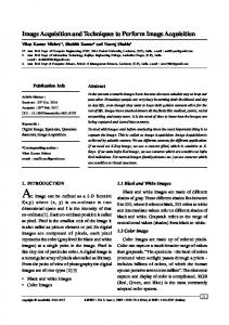
Figure 3: Visualization of calibration objects acquired corresponding to case i) The same three beads (diameter: 1 pm) in a triangle arrangement with immersion oil as mounting medium were acquired under four different perspectives by means of optical sectioning, resulting in four different 3D data sets of the same objects. In the left column the extended view of the xz—image planes (front view) of the four different 3D data stacks corresponding to the four angular positions (0°, 30°, 600, 900) are shown. The middle column shows extended views of the same 3D data stacks under the xy—perspective (top view). In the right column, extended views of the same 3D data stacks but viewed from the zy—perspective (side view) are given. The letters A, B and C indicate an identification of the objects for quantitative analysis as carried out in Table 1. The arrow indicates the direction of the optical axis; bar indicates 5 pm.
SPIE Vol. 2926 / 195
xz
xY
zy
01 30
I
60
90
Figure 4: Visualization of calibration objects acquired corresponding to case ii) The same group of beads within glycerol as mounting medium were acquired under four different perspectives (00, 300, 60° and 90°) by means of optical sectioning, resulting in four different 3D data sets of the same objects. In all 3D data sets, the four beads in the triangle arrangement were imaged. In the left column, the extended view of the xz—image planes (front view) of the four different 3D data stacks corresponding to the four angular positions are shown. The middle column shows extended views of the same 3D data stacks under the xy—perspective (top view). In the right column, extended views of the same 3D data stacks but viewed from the zy—perspective (side
view) are given. The letters A, B and C indicate an identification of the objects for quantitative analysis as carried out in Table 2. The arrow indicates the direction of the optical axis; bar indicates 5 pm.
196 ISP!E Vol. 2926
3. RESULTS It can easily be seen by the front views of the Figures 3 and 4, that the macroscopically adjusted angle by the tilting device is reflected in the arrangement of the measured beads within a certain tolerance range, depending on the image analysis applied. The quality of the object rotation was also tested by the analysis of the normal vector oriented perpendicular to the triangle ABC in all measured perspectives, for both cases. Since the tilting axis is parallel to the y—axis, the y—coordinates of the resulting normal vectors should be invariant and be about 0. This was also found with a high accuracy. The calculated angles between the normal vectors and the yz—plane reflected also the adjusted rotation angles in both setup cases. Especially case ii) clearly demonstrates the usefulness and resolution improvement of the axialtomographical approach for objects which are located next to each other, with a distance of < 1 axial FWHM and > 1 lateral FWHM: the two beads at the corner C of the triangle ABC (see also Fig. 4, top view (xy) for OO) can be resolved as two single objects in the perspective, whereas they appear as one single object in all other perspectives.
Since all the quantitative analysis described here depended on the determination of the centers of mass of the segmented objects, special care was taken in the examination of the segmentation procedure. It was shown that for the spherical objects (beads) used, the center of mass of one object is not depending on the selected threshold. This means, that a precise localization of well separated objects can be achieved far beyond the resolution limit as reported elsewhere [26]. In our case, the standard deviation of the center of mass coordinates was about 15 nm. However, as expected, the volume and the surface of the segmented objects changed with the variation of the global threshold. 3D distances between the identified objects for both cases are given in the Tables 1 and 2. The estimated maximum error of the 3D distance measurements according to theoretical considerations described in [23] were calculated and could be minimized, when the center of mass coordinates were located in the same focal plane. In this case, the z—coordinate of the investigated objects had roughly the same value; in all the other cases, the z—coordinates differed,
being equivalent to a location in different focal planes. However, the 3D distances obtained in all measurements vary within the estimated errors. The 2D distance projection of 3D distances for both cases is also given in Tables 1 and 2. These 2D distances represent the distances which would be determined with a conventional epifluorescence microscope without the tilting approach because of the increased depth of focus. In combination with 3D data stacks of the tilted images of the same group of objects, it is possible to analyze these projected distances with regard to an arbitrary object orientation distribution of biological objects on a conventional cover slide. The results from both Tables show that a maximum distance is found, if the objects are located in the same focal plane. Due to fundamental geometry laws, this distance is the true distance between the objects. For a calibration of the CLSM in the lateral and axial direction the recorded images were used. Since the tilting axis is parallel to the y—axis, the distance of two beads with the same coordinates except x—coordinate should be invariant under tilting within the expected errors. The true distance of two beads B1 (x1 ,Yi , z1 ) and B2 (x2 , Yi , z1) is given by: d = lxi — x21 . Especially when a configuration of two beads as mentioned above is tilted by an angle of 9Q0, the samedistance value should result under the new perspective. The new coordinates of the two objects are in such the resulting distance is then: d = li — z21. This was approxiniately found a case: B1 (ii , Yi z1) and B2(i1 , y , for the distance between the objects AB in the x—direction for the OO and in the z—direction for the 900 position in the case of the mounting medium glycerol (see Table 2). The value IABI = 3.84 jm for the O position, for the 900 position the same distance is measured in z—direction to: IABIZ = 3.74 tim. For immersion oil as the mounting medium, similar results have been found: ABIX = 4.09 pm for the 00 position, IABIZ = 4.28 pm for the 900 position.
i),
4. DISCUSSION In this report, a versatile tilting device for object rotation in combination with a confocal laser scanning microscope
has been investigated for calibration measurements. It was shown by the acquired images, that the manually performed object tilting can be executed in a precise manner. This was estimated by visual inspection from the front views of the extended views and quantified by analysis of the normal vectors of the triangle arrangement of the calibration objects. Furthermore, the usefulness of the axialtomographic approach was shown by a special example: two single objects were distinguished from each other in a perspective where both objects were located in the same focal plane, i.e. under
SP!E Vol. 2926 / 197
optimum resolution conditions; in all other viewing perspectives, those two objects appeared as one. In this case, an a priori knowledge about particle size and shape exists and, thus, contributes to find errors of segmentation. However, for fluorescent targets of unknown shape and size distributed in biological objects, this information may not be available so that a data stack recorded under one perspective only may reveal "optically fused" images of separate objects. Thus, the use of axialtomographic microscopy for high precision 3D distance measurements will be especially important in the study of the 3D distribution of weakly fluorescing objects. A biologically important example for this is the 3D distance in the nucleus between genes related to cancer [27]. With these findings in mind, it is of most importance to image an object under optimal conditions with optimal settings of the CLSM. Only when the image acquisition has a maximal qttality, the deconvolution and segmentation procedures which might follow improve the image, leading to useful quantitative analysis and not inducing wrong interpretations. Due to the influence of specimen and mounting media on the spatial resolution of a CLSM, the focal shift increases with the refractive index mismatch and the depth of the investigated region, leading to distance elongation along the optical axis. Attenuation and absorption effects of excitation and emitted light due to layer thickness and refractive index mismatches decrease of the axial resolution [28, 17]. For calibration purposes and analysis of these effects, images of beads which are located in a O position can be compared with images of the same objects in a 900 position. Since the object distances are invariant if tilting is performed, the analysis of the distances should lead to the same results under both perspectives, if the calibration of the z—positioning was correct. However, the values obtained in this study for the objects AB have a difference of 190 nm for a distance of 4.1 im for immersion oil as mounting medium and 100 nm for a distance of 3.8 jm for glycerol as mounting medium. However, for those "small" distances (d 4 jim) ,the predicted effect cannot clearly be shown (- . 4pm = 4.l6pm). The deviation above might also be due to the increase of the axial FWHM, which leads also in an unsymmetrical shape and therefore resulting in a wrong lokalisation of the center of mass. For a larger distance between test objects i.e. embedded in water, this calibration method can be applied with higher accuracy, because the differences in the "true" distance d and the measured tilted distance d is more obvious and greater than the axial FWHM.
5.
ACKNOWLEDGEMENTS
The financial support of this study by the Deutsche Forschungsgemeinschaft is gratefully acknowledged. B. Rinke receives a DFG scholarship as a member of a DFG graduate college. We thank Prof. T. Cremer; Institute of Anthropology and Human Genetics, University Munich, for the access to the confocal laser scanning microscope TCS 4D and for stimulating discussions.
References {1] A. Waggoner, R. De Biasio, P. Conrad, G.R. Bright, L. Ernst, K. Ryan, M. Nederlof, and D. Taylor. Multiple spectralparameter imaging. Meth. Cell Biol., 30:449—478, 1989. [2] P. Lichter, A.L. Boyle, T. Cremer, and D.C. Ward. Analysis of genes and chromosomes by non—isotopic in situ hybridization. Genet. Anal. Techn. Appi., 8:24—34, 1991. { 3] C. Cremer and T. Cremer. Analysis of chromosomes in molecular tumor and radiation cytogenetics: Approaches, applications, perspectives. Europ. J. Histochem., 36:15—25, 1992.
[4] T. Cremer, A. Kurz, R. Zirbel, S. Dietzel, B. Rinke, E. Schröck, M.R. Speicher, U. Mathieu, A. Jauch, P. Emmerich, H. Schertan, T. Ried, C. Cremer, and P. Lichter. Role of chromosome territories in the functional compartmentalization of the cell nucleus. Cold Spring Harb. Symp. Quant. Biol., 58:777—792, 1993.
[5] R.M. Zirbel, U.R. Mathieu, A. Kurz, T. Cremer, and P. Lichter. Evidence for a nuclear compartment of transcription and splicing located at chromosome domain boundaries. Chrom. Res., 1:93—106, 1993.
[6] T. Ried, V. Mahler, P. Vogt, L. Blonden, G.J.B. van Ommen, T. Cremer, and M. Cremer. Carrier detection by in situ suppression hybridization with cosmid clones of the Duchenne/Becker muscular dystrophy (DMB/BMD) locus. Hum. Genet., 85:581—586, 1990.
198 ISPIE Vol. 2926
[ 7]
C. Cremer and T. Cremer. Considerations on a laser—scanning—microscope with high resolution and depth of field. Microsc. Acta (Stuttgart), 81:31—44, 1978.
[8J G.J. Brakenhoff, H.T.M. van der Voort, E.A. van Spornsen, W.A.M. Linnemans, and N. Nanninga. Three di— mensional chromatin distribution in neuroblastoma nuclei shown by confocal scanning laser microscopy. Nature, 317:748—749, 1985. [9]
J.B. Pawley. Handbook of Biological Confocal Microscopy. Plenum Press, New York, 1990.
[10J S. Hell and E.H.K. Stelzer. Properties of a 4Pi confocal fluorescence microscope. Opt. Soc. Am., A9:2159—2166, 1992.
[11] F. Lanni, A.S. Waggoner, and D.L. Taylor. Standing wave luminescence microscopy. US patent No 4, 621, 911, 1986. {12]
B. Schneider, J. Bradi, I. Kirsten, M. Nagorni, B. Rinke, M. Hausmann, and C. Cremer. Distance measurements of single targets by wavefield microscopy. Manuscript in preparation, 1996.
[13] C.J.R. Sheppard. Depth of field in optical microscopy. J. Microsc., 149:73—75, 1987.
[14] B. Richards and E. Wolf. Electromagnetic diffraction in optical systems II. Structure of the image field in an aplanatic system. Proc. Roy. Soc., A 253:358—379, 1959.
[15J J. W. Goodmann. Introduction to Fourier Optics. McGraw Hill, New York, 1968.
[16] Y. Hiraoka, J.W. Sedat, and D.A. Agard. Determination of three-dimensional imaging properties of a light microscope system. Partial confocal behavior in epifluorescence microscopy. Biophys. J., 57:325—333, 1990. [17] 5. Hell, G. Reiner, C. Cremer, and E.H.K. Stelzer. Aberrations in confocal fluorescence microscopy induced by
mismatches in refractive index. J. Microsc., 169:391—405, 1993. {18J
B. Rinke, J. Bradi, B. Schneider, M. Durm, M. Hausmann, H. Ludwig, and C. Cremer. Fluorescence Microscopy & Fluorescent Probes, "in situ" estimates of the spatial resolution for "practical" fluorescence microscopy of cell nuclei,
[19]
178—183. Plenum Press, 1996.
R.J. Skaer and S. Whytock. Interpretation of the three—dimensional structure of nuclei by specimen tilt. J. Cell Sci., 19:1—10, 1975.
[20] P.J. Shaw, D.A. Agard, Y Hirakoa, and J.W. Sedat. Tilted view reconstruction in optical microscopy: three dimensional reconstruction of drosophila melanogaster embryo nuclei. Biophys. J., 55:101—110, 1989.
[21] J. Bradl, M. Hausmann, V. Ehemann, D. Komitowski, and C. Cremer. A tilting device for 3—D microscopy: application to in situ imaging of interphase cell nuclei. J. Microsc., 168:47—57, 1992. [22]
J. Bradl, M. Hausmann, B. Schneider, B. Rinke, and C. Cremer. A versatile 2rr—tilting device for fluorescence microscopes. J. Microsc., 176:211—221, 1994.
[23] J. Bradi, B. Rinke, M. Hausmann, B. Schneider, and C. Cremer. Improved resolution in "practical" light microscopy by means of a glass fibre 2ir—tilting device. Proc. SPIE 2628, 140—146, 1996.
[24] J. Rasure and C. Williams. An integrated data flow visual language and software development environment. J. Vis. Lang. Comp., 2:217—246, 1991.
[25] K. Konstatinides and J. Rasure. The Khoros software development environment for image and signal processing. IEEE Trans. Image Proc., 3(3):243—252, 1994.
[26] U. Kubitscheck, P. Wedekind, 0. Zeidler, M. Grote, and R. Peters. Single nuclear pores visualized by confocal microscopy and image processing. Biophys. J., 70:2067—2077, 1996.
[27] D. C. Tkachuk, C. A. Westbrook, M. Andreeff, T. A. Donlon, M. L. Cleary, K. Suryanarayan, M. Homge, A. Render, J. Gray, and D. Pinkel. Detection of bcr—abl fusion in chronic myelogeneous leukemia by in situ hybridization.
Science,
250:559—562, 1990.
SPIE Vol. 2926 / 199
[28] T.D. Visser, J.L. Oud, and G.J. Brakenhoff. Refractive index and axial distance measurements in 3D microscopy. Optik, 90:17—19, 1992.
200 / SPIE Vol. 2926