IMAGE TRANSMISSION OVER FADING CHANNELS USING RS-CC VERSUS LDPC CODING Erhan A. İnce, Edmond Nurellari, Leonardo O. Iheme Eastern Mediterranean University Electrical & Electronic Eng., Famagusta, TRNC, via Mersin 10 Turkey. Email:
[email protected],
[email protected],
[email protected] ABSTRACT In this paper we present effective means of digital image transmission by means of Forward Error Correcting (FEC) schemes and Orthogonal Frequency Division Multiplexing (OFDM). The transmission was simulated over the AWGN and a Rayleigh fading channel whose power delay profile was adopted from the ITU channel model. The FEC and OFDM parameters were adopted from the DVB-T, WiMAX, and DVB-T2 standards. The results presented herein are in terms of BER, PSNR and visual performances. It is evident from the presented results that effective FEC schemes are necessary for reliable transmission of digital media in a mobile wireless scenario. KEY WORDS Low-Density Parity-Check; Reed Solomon; OFDM; Rayleigh Fading Channel; Digital Image Processing.
1. Introduction The need to transmit digital multimedia over wireless channels has grown over the years because of the convenience that comes with it. The challenge of the wireless channel however is overwhelming- thus researchers have come up with various solutions to minimizing or possibly overcoming the adverse effects of the wireless channel. Advanced technologies such as WiMAX [1], DVB-T and DVB-T2 [2] have been developed to meet the needs of the teeming consumers. Such technologies have gained acceptance because of their capabilities to reliably deliver multimedia content to end users. Some of the FEC schemes adopted by the above mentioned standards include convolutional coding, Reed Solomon (RS) coding, LDPC coding and/or concatenated BCH and LDPC coding. In concatenated coding typically, there is an outer code and an inner code. The code rate and the data rate of the transmission is mainly controlled by the inner code [3]. After FEC, the data is modulated either by vector modulation, amplitude modulation, frequency modulation or in this case, orthogonal frequency division multiplexing (OFDM). OFDM is suitable for outdoor mobile communications because of its advantageous features [4]. The disadvantages associated with the
technology come at a relatively cheap cost; thus making it the choice modulation for WiMAX, DVB-T and DVB-T2 schemes. Low-density parity-check codes and Turbo Codes (TCs) [5] are among the known FEC codes that give performances nearing the Shannon limit. In this work we chose to concentrate on LDPC usage instead of the TCs since LDPC decoding algorithms have more parallelism, less implementation complexity and less decoding latency [6]. Our simulations were carried out for a purely additive White Gaussian Noise channel and a fading channel with AWGN noise. For the fading channel the Jakes fading channel model [7] together with ITU Vehicular-A [8] power delay profile parameters were used considering also the Doppler effect. Three scenarios are presented in the paper: simulation of concatenated RS-CC and optional LDPC coding as suggested by the WiMAX standard, simulation of RS-CC using the DVB-T parameters and simulation of DVB-T2 using LDPC without outer BCH encoder. The paper organization is as follows: Section II provides a brief summary about concatenated RS-CC coding and LDPC codes used by the DVB-T2 and WiMAX standards. In Section III Jakes’ fading channel model and the power delay profile parameters used for the ITU channel is introduced. The system parameters chosen for simulation purposes are given in section IV. In section V the results obtained using the FEC coding schemes of the European standards DVB-T and DVB-T2 and mobile WiMAX are presented and compared. Lastly in section VI conclusions are drawn.
2. Forward Error Correction In this section, FEC schemes used in this paper are described in brief. 2.1 Concatenated Reed Solomon and Convolutional Coding Reed Solomon coding is a well-known technique for FEC; it has been used for such applications as the Compact Disk. Data is collected into a specific size and is provided with a distinctive checksum of a specific size. This checksum allows not only errors to be detected but also a definite number of errors to be corrected. The number of
errors which can be corrected is a direct function of the size of the checksum. In WiMAX, the downlink of the OFDM mode uses an outer systematic RS code derived from an RS(n = 255, k = 239, T = 8) code using GF(28) [9]. In DVB-T and DVB-T2 however, the RS code is chosen such that one transport stream packet is chosen as one data block- the RS(n = 204, k= 188) code is therefore chosen. Both RS codes are capable of correcting up to 8 errors at the receiving end. Convolutional codes act on binary data, adding redundant bits based on the block of data they are processing. It has been shown in [10] that without concatenation, convolutional codes perform better than Reed Solomon codes in fading channels. Even though the outer RS encoder reduces the data rate by a factor of k/n the net data rate is controlled by the inner, more powerful convolutional encoder whose code rate is k/n [11].In both cases (WiMAX and DVB-T) the inner coder is a ½ rate convolutional code (G1=171oct; G2=133oct). Convolutional codes are decoded by means of Viterbi decoders; in concatenated scenarios, Viterbi decoding is done just before the RS decoder. The analysis done in [12] has been widely used and has been shown to yield results that very closely approximate simulation results.
Here Pi,j corresponds to either a (z×z) permutation matrix or (z×z) zeros matrix. The matrix H given in the above form can be expanded to a binary base matrix Hb of size (mb×nb) where and as stated in [15]. The permutations used are circular shifts, moreover the set of permutations matrices contains the (z×z) identity matrix and circular right shifted versions of the identity matrix. In [16] a binary base matrix H has been defined for the largest codeword length (n=2304) for various code rates. Since the base model matrix has 24 columns, the so called expansion factor zf=n/24 for codeword length of n. For codeword length of 2304 the expansion factor would be 2304/24=96. Given a base model matrix Hbm, when ( ) it will be replaced by a (z×z) all-zero matrix and the other elements which correspond to ( ) will be replaced by circular shifting of the identity matrix by ( ). For code rate ½, the base model matrix Hbm is defined as:
(3) 2.2 LDPC Coding A low-density parity-check (LDPC) code is a linear block code with a low density parity check matrix [13]. LDPC codes are classified into two groups; regular LDPC codes and irregular LDPC codes [14]. Regular LDPC codes have equal column and row weight, and irregular LDPC codes have different column and row weight. Each LDPC code is defined by a matrix Hof size (m × n), where n defines the code length and m defines the number of parity check bits in the code. The number of systematic bits would then be k=n-m. The parity check matrix can be represented in the form H = [In-k | PT] where In-k is identity matrix and P is the coefficient matrix. A sample (3×7) parity check matrix is given in equation (1): [
|
]
(1)
In this paper parity check matrix for WiMAX and DVB-T2 standards have been generated. The H matrix for optional LDPC coding has been defined in the WiMAX standard IEEE Std 802.16e™-2005 and is as follows:
(2) [
]
The parity-check matrix of the LDPC code for DVBT2 standard with code rates R (1/4, 1/3, 2/5, 1/2, 3/5, 2/3, 3/4, 4/5, 5/6, 8/9, 9/10) are possible. In this paper we are generating H matrix supporting 1/4 and 1/3 code rates. The block length of the code is fixed to 64800.
3. Fading Channel Model The ITU-Vehicular A adopted channel model is empirical, based on measured data in the field. The tapped-delay-line parameters for this channel are shown in Table 1. Table 1 Tapped-delay-line parameters for ITU Vehicular-A channel model Average Relative Delay Tap Index Power (ns) (dB) 1 0 0 2
310
-1
3
710
-9
4
1090
-10
5
1730
-15
6
2510
-20
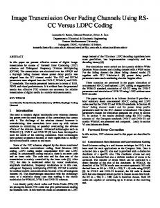
3.1 Jakes’ Fading Simulator Jakes’ model which is based on summation of sinusoids can be easily modeled as described in [7]. The aim is to produce a signal that possesses the same Doppler spectrum as that of the classic Doppler spectrum. Details of the channel model depicted in Figure1 can be found in [7]. Jakes’ model which is based on summation of sinusoids can be easily modeled as described in [14]. The aim is to produce a signal that possesses the same Doppler spectrum as that of the classic Doppler spectrum. Details of the channel model depicted in Figure 1 can be found in [14].It is possible for one to generate this model by generating two independent Gaussian random variables namely: ( ) and ( ). Jakes’ model is based on summing sinusoids as defined by the following equations: ( ) ( )
( )
( )
√ {[ ∑
]
where
(
cosωMt 2sinβM
2cosβM
2sinα
2cosα
+
+ y(t)
g(t) = x(t) + jy(t)
̂
( )
̂
( )
̂ ̂
2cosβ1
x(t)
]}
̂
cosω1t 2sinβ1
1/√2cosωmt
( )
[ ∑
̂
Offset oscillators
(4)
√
√
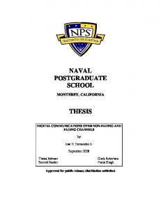
length. The cyclic prefix is a unique feature of OFDM that protects the data from inter-symbol interference (ISI). Once this has been done, the image is then transmitted over the channel where it is affected by noise and multipath. Figure 2 provides a block diagram representation for the entire transmission and reception system.
Figure 1. Jakes' fading channel model
)
and ⁄
, .
From the above development, the fading simulator shown in Figure 2 can be constructed. There are low frequency ( ) oscillators with frequency where ( ) where is the number of sinusoids. The amplitudes of the oscillators are all unity except for the oscillator at frequency which has amplitude ⁄√ Note that Figure 2 implements ( ) except for the scaling factor of √ . It is desirable that the phase of ( ) be uniformly distributed.
4. System Model and Parameters This section summarizes all the parameters used in the simulations of the image transmission. After the image is acquired, it is converted to gray scale and then passed into the FEC block where the bit and/or symbol stream is channel encoded. The encoded stream is then fed into the constellation mapper, QPSK in our study. This constellation mapper produces one symbol for every two bits, after which the signal is modulated by IFFT and lengthened by addition of a cyclic prefix of a certain
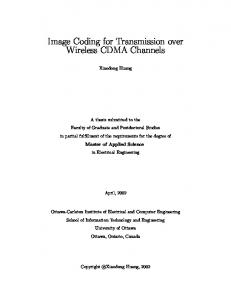
Figure 2. Image transmission model The RS, CC, and the LDPC code rates adopted by our simulations (FEC schemes designed for DVB-T, DVB-T2 and IEEE 802.16e standard), the maximum Doppler frequency and the type of fading channels used are provided in Table 2. Two grey scale images of size 180×240 were protected by the FEC schemes and transmitted over the AWGN and fading channels. The quality of reception was measured by observing bit error rate (BER) and peak signal to noise ratio (PSNR) values over a set of SNR values. The original images used are as depicted in Figure 3.
Table 2 System parameters WiMAX ( (
FEC
DVB-T )
( (
) ) )
( (
Channel
ITU-Vehicular A channel
Doppler spectrum Max. Doppler Frequency
Jakes’
DVB-T RS(204,188,8) CC(2,1,7) IEEE 802.16e RS(255,239,8) CC(2,1,7)
DVB-T2 )
)
0
10
(
)
(
)
10
-1
-2
BER
Parameter
10
10
300 Hz
10
10
-3
-4
-5
0
0.5
1
1.5 Eb/N0 (dB)
2
2.5
3
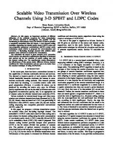
Figure 4. BER performance over the AWGN channel using RS-CC coding
(a)
(b)
Figure 3. Transmitted images
5. Simulation Results This section sets out to show the link-level BER and PSNR performances of RS-CC and LDPC coded QPSKOFDM over AWGN and multipath Rayleigh fading channels. Four different scenarios are considered. Firstly the RS-CC concatenated coding with RS(255,239,8) and CC(1,2,7) as suggested in the mobile WiMAX standard is simulated. Then, RS(204,188,8) and CC(1,2,7) stated by the European DVB-T standard is simulated and compared against previous set of results.
The system’s BER performance over the AWGN channel using the optional LDPC coding of mobile WiMAX and LDPC coding of DVB-T2 has been summarized in Figure 5. Even though more than two code rates are possible for each standard, in this work only two code rates leading to better performances were chosen for each standard. As can be observed from the figure the best BER is obtained using the rate R= ½ LDPC code for IEEE 802.16e. Zero error decoding becomes possible after an SNR of 1dB. The second best BER is attained while using the rate R = ¼ LDPC code for the DVB-T2. Here Zero error decoding becomes possible after 3dB. In order to assess the quality of the recovered images the peak signal to noise ratio (PSNR) was also examined for the LDPC code rates depicted in Figure 5. For the various SNR values shown in Table 3 the PSNRs were computed using: (
In order to compare and contrast the performance of concatenated coding with those of LDPC coded system performances the code rates and corresponding parity check matrices provided in Table 2 (as suggested in DVBT2 and mobile WiMAX) were also simulated.
( (
)
)) (8)
∑∑
( (
)
̂(
))
Where, max (g(x,y)) is the maximum possible pixel value in the (u×v) image. 5.1 Image Transmission over AWGN Channel Figure 4, depicts the BER performance of the RS-CC coded system over the AWGN channel using the image shown in Figure 3(a) and the RS and CC parameters stated in the mobile WiMAX and DVB-T standards. The slight difference in coding gains achieved by the two RS-CC curves is as a result of shortening the code word length. As noted in [17] a shorter code word length will improve the performance of the RS encoder.
SNR (db) 0 1 2 3
Table 3 PSNR performance using LDPC codes over the AWGN channel WiMAX DVB-T2 R=2/3 B R=1/2 R=1/4 R=1/3 PSNR (dB) 13.87 11.05 --19.49 11.48 10.07 9.93 Inf 12.12 10.83 10.31 Inf 12.87 14.85 10.94
10
0
quality of the received image progressively improves as the SNR increases. For SNR values equal to and greater than 20dB, error free reception is achieved.
BER
DVB-T2 LDPC R(1/4) DVB-T2 LDPC R(1/3) IEEE 802.16e LDPC R(2/3 B) IEEE 802.16e LDPC R(1/2)
10
10
-1
SNR = 4dB
SNR = 10dB
SNR = 16dB
SNR = 20dB
-2
0
1
2
3
4 5 Eb/No (dB)
6
7
8
9
Figure 5. BER performance over AWGN channel using LDPC coding
5.2 Image Transmission over Fading Channels This section provides a comparative analysis for RSCC and LDPC coded system performances over the ITU Vehicular-A channel. Fading channels are known to degrade the system’s BER performance more than an AWGN channel. The parameter which affects data transmission the most in the context of small scale fading is the Doppler frequency. In this work, the Doppler frequency assumed was 300 Hz. This amount of shift roughly corresponds to a speed of 90 km/hr. Figure 6 shows the RS-CC coded system performance for both the DVB-T and the IEEE 802.16e standards. Clearly both coding schemes lead to very close BER performances. 10
0
IEEE 802.16e RS(255,239,8) CC R(1/2) DVB-T RS(204,188,8) CC(2,1,7)
-1
BER
10
10
10
-2
-3
0
2
4
6 8 Eb/N0 (dB)
10
12
14
Figure 6. DVB-T vs. IEEE802.16e over the ITU Vehicular-A channel Figure 7 depicts the recovered images transmitted using DVB-T over the ITU Vehicular-A channel for SNR values of 4, 10, 16 and 20dB. As can be observed, the
Figure 7. Recovered images transmitted using DVB-T over the ITU Vehicular-A channel The computed PSNR values for the RS-CC coding of DVB-T standard has been summarized for both the AWGN and ITU Vehicular-A channels in Table 4. Note that over the AWGN channel a PSNR value of 30.37 dB is attained for an SNR value of 2.25dB. However on the ITU Vehicular-A channel a similar performance is only possible around 15dB. This clearly points out the degrading effect of the fading mobile communication channel. Table 4 PSNR performance using RS-CC scheme of DVB-T standard (RS (204, 188, 8) and CC (1, 2, 7)) over additive and fading channels Fading Channel AWGN ITU Vehicular-A SNR PSNR SNR PSNR 0 13.04 0 9.46 0.25 14.14 2 11.26 0.50 15.50 4 13.57 0.75 16.69 6 15.88 1 18.22 8 19.02 1.25 19.81 10 22.83 1.50 21.74 12 22.34 1.75 23.47 14 26.82 2 26.16 16 32.41 2.25 30.37 18 Inf 2.50 Inf 20 Inf The next set of simulation results are from using LDPC parameters for WiMAX and DVB-T2 (please refer to Table 2). In Figure 8, the IEEE 802.16e LDPC code with rate R=½ performs best with zero error decoding starting at an SNR of about 5dB. The second best
BER
performance is attained by using the rate R = ¼ LDPC code dictated by the DVB-T2 standard as the FEC scheme. 10
0
10
-1
10
-2
10
-3
DVB-T2 LDPC R(1/4) DVB-T2 LDPC R(1/3) IEEE 802.16e LDPC R(2/3 B) IEEE 802.16e LDPC R(1/2) 10
-4
0
2
4
6
8
10
12
14
16
18
20
Eb/No (dB)
Figure 8. BER performance over Rayleigh fading channel using LDPC coding In Figure 9 we make a comparison of the best LDPC codes with the concatenated RS-CC codes in order to highlight the drastic improvement in the performance of the system when LDPC codes are used in a Rayleigh fading channel with the consideration of Doppler effect. For example there is a coding gain of about 9 dB for a target BER of when the IEEE 802.16e LDPC R = ½ is used instead of the IEEE 802.16e RS(255, 239, 8) CC(2, 1, 7). Clearly the usage of LDPC encoders brings a big improvement to the system’s BER performance. 10
0
BER
DVB-T RS(204,188,8) CC(2,1,7) IEEE 802.16e RS(255,239,8) CC R(1/2) DVB-T2 LDPC R(1/4) IEEE 802.16e LDPC R(1/2) 10
-1
10
-2
10
-3
10
-4
0
2
4
6 8 Eb/N0 (dB)
10
12
14
Figure 9. Comparison of BER performance over Rayleigh fading channel using LDPC coding and concatenated RS-CC coding All the PSNR values for received images while using rate R = ½ and R = 2/3B WiMAX LDPCs and rate R= ¼ and R = 1/3 DVB-T2 LDPC encoders have been provided in Table 5.
Figure 10 and 11 depict the recovered images after LDPC decoding of the received data sequences. For WiMAX with R=½ error free reception is possible after 5dB. Similarly for the DVB-T2 LDPC with rate R=¼ error free reception starts around 8dB.
Table 5 LDPC performance over the ITU Vehicular-A channel WiMAX DVB-T2 SNR (db) R=1/2 R=2/3 B R=1/4 R=1/3 PSNR (dB) 1 12.29 11.92 9.54 9.47 2 13.22 12.44 9.96 9.72 3 14.35 13.01 10.61 10.15 4 32.85 13.68 12.05 10.54 5 Inf 14.47 16.93 11.50 6 Inf 15.27 22.67 15.16 7 inf 16.03 41.98 22.42 8 Inf 16.98 Inf Inf
6. Conclusions In this paper the effect of using two types of channel coding schemes on an image transmitting system’s link level BER performance has been investigated. Mainly RSCC concatenated codes used in DVB-T and WiMAX standards along with LDPC codes for DVB-T2 and mobile WiMAX standards have been considered while transmitting digital images. Testing was carried out over the AWGN and ITU Vehicular-A Rayleigh fading channel. On the AWGN channel the R= ½ LDPC code of mobile WiMAX gives better BER performance than the RS-CC concatenated codes of DVB-T and WiMAX. Not all the LDPC codes are better at low SNRs when compared to the RS-CC coding. Based on the code structure and the degree of sparsity of the parity check matrix some LDPC codes can lead to a higher BER at low SNRs (0-4 dB) when compared to RS-CC coded systems performance. On the ITU Vehicular-A Rayleigh fading channel, zero error decoding is quickly achieved by the rate R = ½ and R = ¼ LDPC codes when compared to the RS-CC. For a BER of 0.01 the R= ½ LDPC coding for WiMAX has about 8 dB gain over the RS-CC concatenated codes for DVB-T and WiMAX and similarly the R = ¼ LDPC code for DVB-T2 has approximately 6dB gain over the RS-CC concatenated coding. Based on the work presented in [18] it is clear that if LDPC codes are used with outer RS and/or BCH codes even a higher gain would become possible.
SNR = 1dB
SNR = 3dB
SNR = 5dB
SNR = 6dB
Figure 10. Recovered image transmitted over ITU-Vehicular A channel using (R = ½) LDPC as the FEC scheme
SNR = 1dB
SNR = 3dB
SNR = 5dB
SNR = 7dB
Figure 11. Received image transmitted over ITU Vehicular-A channel using (R = ¼) LDPC as the FEC scheme.
References [1] “Standard for Local and Metropolitan Area Networks – Part 16: Air Interface for Fixed and Mobile Broadband Wireless Access Systems – Amendment 3: Management Plane Procedures and Services (Amendment to IEEE 802.16-2004),” IEEE Approved Drafts Std P802.16g/D9, Apr 2007. [2] ETSI EN 302 755 V1.1.1(2009-09): Digital Video Broadcasting (DVB): Frame structure channel coding and modulation for a second generation digital terrestrial television broadcasting system (DVB-T2), Sep 2009. [3] W. Fischer, Digital Video and Audio Broadcasting Technology A Practical Engineering Guide, 2nd Ed., Springer, 2009.
[4] R. Prasad, OFDM for Wireless Communication Systems, Artech House Inc., Boston, 2004. [5] V. Branka, Y. Jinhong, “Turbo Codes: Principles and Applications,” Kluwer Academic Publisher, Boston, 2000. [6] C.A. Eun, J.Ji-Won; K. Nae-Soo; O.Deock-Gil; “Complexity-reduced algorithms for LDPC decoder for DVB-S2 systems”, ETRI Journal, vol. 27, No: 5, Oct 2005, pp. 639-642. [7] W.C. Jakes, Microwave Mobile Communications, Piscataway, NJ:IEEE Press, 1994. [8] ITU-R Recommendation M.1225, “Guidelines for evaluation of radio transmission technologies for IMT-2000, 1997. [9] L., Nuaymi, WiMAX: Technology for Broadband Wireless Access, New York, NY: Wiley, 2007. [10] D.N.K., Jayakody; L.O., Iheme; E.A., Ince; "Coded QPSK-OFDM for data transmission over fading channels," 5th International Conference on Information and Automation for Sustainability (ICIAFS 2010), vol., no., 17-19 Dec. 2010, pp. 276282. [11] W. Fischer, Digital Video and Audio Broadcasting Technology: A Practical Engineering Guide, 2nd Ed., Springer 2009. [12] R. Cideciyan, E. Eleftheriou, and M. Rupf, “Concatenated Reed-Solomon / Convolutional Coding for Data Transmission in CDMA-Based Cellular Systems,”IEEE Trans. on Commun., Vol. 45, No. 10, Oct. 1997, pp. 1291-1303. [13] R. G., Gallager;, "Low-density parity-check codes," Information Theory, IRE Transactions on , vol.8, no.1, January 1962 , pp. 21-28. [14] D. J.C. Mackay; R. Neal; “Near Shannon Limit Performance of Low Density Parity Check Codes”, Electronics Letters, Vol.33, Mar 1997, pp. 457-458. [15] “Part 16: Air Interface for Fixed Broadband Wireless Access Systems Amendment for Physical and Medium Access Control Layers for Combined Fixed Operation in Licensed Bands”, IEEE P802.162004, October 2004. [16] “Part 16: Air Interface for Fixed Broadband Wireless Access Systems Amendment for Physical and Medium Access Control Layers for Combined Fixed Operation in Licensed Bands”, IEEE P802.16e-2005, October 2005. [17] L. J. Deutsch; “The Effects of Reed-Solomon Code Shortening on the Performance of Coded Telemetry Systems”; TDA Progress Report 42-75; Jul-Sept 1983. [18] L. T., Hyung; L.H. Sang;J.K.Eon;, "Performance of Concatenated Code with Hierarchical Modulation in T-DMB System ," 4th Int. Conf. on Elect. And Comp. Eng.(ICECE 2006), Dec 2006, pp. 282-285.