coherent detector based on a maximum likelihood sequence estimator for ... allocation algorithms for coherent and non-coherent AF relay networks taking into ...
1468
IEEE TRANSACTIONS ON WIRELESS COMMUNICATIONS, VOL. 8, NO. 3, MARCH 2009
Impact of Imperfect Channel Estimation on the Performance of Amplify-and-Forward Relaying Berna Gedik and Murat Uysal
Abstract—In this paper, we investigate the error rate performance of amplify-and-forward (AF) relaying with imperfect channel estimation. We consider a single-relay scenario with orthogonal and non-orthogonal AF (OAF and NAF) cooperative protocols. Two pilot-symbol-assisted receiver architectures are studied: In the mismatched-coherent receiver, the complex fading channel coefficients (i.e., both phase and amplitude) are estimated based on a linear minimum-mean-squared-error estimation approach and fed to a coherent sub-optimal maximum likelihood decoder as if the channels were perfectly known. In the partiallycoherent receiver, channel amplitude is ignored and phase is estimated by a phase locked loop. For both receiver types, we analyze the achievable diversity orders for cooperative protocols under consideration and quantify the impact of channel estimation through the derivation of pairwise error probability. Our performance analysis reveals that a second order diversity order is obtained for the considered single-relay scenario indicating that full diversity is extracted. Our simulation results demonstrate that the performance degradation due to channel estimation with respect to the genie bound (i.e., perfect channel state information) is as small as 1.1dB based on the employed detector. Performance results further show that partially-coherent receiver presents a similar performance to mismatched-receiver for sufficiently large loop SNRs although channel amplitude is completely ignored. Index Terms—Transmission technology, cooperative diversity, space-time coding.
I. I NTRODUCTION
C
OOPERATIVE diversity has been proposed as a powerful means to enhance the performance of high-rate communications over wireless fading channels [1]–[3]. It realizes spatial diversity advantages in a distributed manner where two or more nodes (each with single antenna) share their antennas to mimic a virtual antenna array. Cooperative diversity has garnered much attention in the past few years with a flurry of papers (see e.g., the survey papers [4]–[6] and the references therein) providing insights into capacity and power savings realizable through cooperation. However, most of the research efforts on this topic have been mainly limited to some idealistic assumptions such as the availability of perfect channel state information (CSI). Some research efforts on differential and non-coherent detection should be noted [7]– [11] in a related context. Under the assumption of coherent detection, the fading channel coefficients need to be first Manuscript received February 22, 2008; revised June 21, 2008; accepted August 19, 2008. The associate editor coordinating the review of this paper and approving it for publication was D. Dardari. M. Uysal is with the Department of Electrical and Computer Engineering, University of Waterloo, Canada. B. Gedik is currently affiliated with General Electric Company (e-mail: {bgedik, muysal}@engmail.uwaterloo.ca). The work of M. Uysal is supported in part by an NSERC Special Opportunity Grant (SROPJ305821-05). Digital Object Identifier 10.1109/TWC.2008.080252
estimated and then used in the detection process. In decodeand-forward (DF) relaying, both relay and destination require a reliable channel estimate. In amplify-and-forward (AF) relaying, knowledge of CSI is required at the destination terminal and may be required at the relay as well depending on the adopted scaling factor [12]. The quality of channel estimates inevitably affects the overall performance of relay-assisted transmission and might become a performance limiting factor. Channel estimation problem in the context of DF relaying basically consists of individual estimation of source-to-relay and relay-to-destination channels. On the other hand, in AF relaying, a cascaded channel from source-to-destination needs to be estimated. Although it can be possibly argued that this could be disintegrated into individual channel estimations (i.e., separate estimations of source-to-relay and relay-to-destination channels) through the injection of a “clean” pilot symbol at relay, such an approach would require additional pilot symbols, therefore reduce the bandwidth and power efficiency. It would also require the forward-feedback of source-to-relay channel estimate from the relay to destination terminal which would be subject to further distortions during transmission. Therefore, in this paper, we devote our attention to AF relaying with channel estimation of the overall cascaded channel. To the best of our knowledge, coherent detection with imperfect channel estimation for AF relaying has been first addressed by Mheidat and Uysal in [13] and independently by Patel and Stuber in [14], [15]. The main focus in [13] and its journal version [11] is actually the derivation of a noncoherent detector based on a maximum likelihood sequence estimator for distributed space-time block codes whereas the performance of a mismatched-coherent receiver (i.e., coherent detection with imperfect channel estimation) is studied as a benchmark. On the other hand, [15] considers a multi-hop relay scenario, derives a channel estimator tailored for cascaded Rayleigh fading channel, and further presents an approximate bit error rate performance analysis for a mismatched-coherent receiver. Furthermore, in [37], Quek et al. propose power allocation algorithms for coherent and non-coherent AF relay networks taking into account imperfect channel knowledge. In this paper, we investigate the effects of channel estimation on the performance of both orthogonal AF (OAF) [16] and non-orthogonal AF (NAF) relaying1 [17] which correspond to distributed SIMO (single-input multiple-output) and MIMO (multiple-input multiple-output) implementations, respectively [3]. We consider mismatched-coherent and partially-coherent receivers at the destination terminal. In mismatched-coherent 1 Orthogonal and non-orthogonal AaF relaying are referred as Protocol II and Protocol I, respectively in [3].
c 2009 IEEE 1536-1276/09$25.00 �
Authorized licensed use limited to: University of Waterloo. Downloaded on July 29, 2009 at 12:52 from IEEE Xplore. Restrictions apply.
GEDIK and UYSAL: IMPACT OF IMPERFECT CHANNEL ESTIMATION ON THE PERFORMANCE OF AMPLIFY-AND-FORWARD RELAYING
receiver, the channel coefficients are first estimated through pilot symbols based on a linear minimum-mean-squared-error estimation (LMMSE) approach and then fed to a coherent maximum likelihood (ML) decoder as if the channel was perfectly known. In partially-coherent receiver, the estimates of channel phase information are obtained through a phase lock loop (PLL) while no effort is made for the estimation of channel amplitudes. Considering these two receiver-types, we quantify the impact of channel estimation on OAF and NAF relaying through the derivations of pairwise error probability (PEP) and a comprehensive Monte-Carlo simulation study. The rest of the paper is organized as follows: In Section II, we introduce the relay-assisted transmission and describe the received signal models for OAF and NAF relaying. In Section III, we describe pilot-symbol-assisted LMMSE channel estimation and PLL-aided phase estimation. In Section IV, we provide PEP expressions for the two receiver types under consideration. In Section V, we discuss the effect of relay location on channel estimation. In Section VI, we present an extensive Monte-Carlo simulation study to demonstrate the error rate performance of OAF and NAF cooperation protocols with mismatched-coherent and partially-coherent receivers. The conclusions are given in Section VII. Finally, the details of PEP derivations are provided in the appendixes. T ∗ H Notation: (.) , (.) , (.) denote transpose, conjugate, and Hermitian transpose operations, respectively. E (.) denotes expectation. |.| denotes the absolute value, �.� denotes the Frobenius norm and IN denotes the identity matrix of size N . var (.) denotes the variance of a random variable. det (.), diag (.), and trace (.) denote the determinant, diagonal, and √ trace of a matrix, respectively. i denotes −1. Re(.) denotes real part. Bold upper-case letters denote the matrices and bold lower-case letters denote the vectors. II. S YSTEM M ODEL We consider a single-relay scenario where each of the halfduplex nodes is equipped with a single pair of transmit and receive antennas (Fig. 1). To incorporate the effect of relay geometry in our model, we consider a channel model which takes into account both long-term free-space path loss and short-term Rayleigh fading. The path loss is proportional to d−a where d is the propagation distance and a is the path loss coefficient. In Fig. 1, dSD , dSR , and dRD denote the distances of source-to-destination (S→D), source-to-relay (S→R), and relay-to-destination (R→D) links, respectively, and θ is the angle between lines S→R and R→D. Assuming the path loss in S→D to be unity, the relative gain of S→R and R→D links a a are defined as GSR = (dSD /dSR ) and GRD = (dSD /dRD ) [18]. We consider two cooperation protocols: In OAF protocol [16], the source terminal communicates with the relay and destination terminals over the first signaling interval. In the second signaling interval, only the relay terminal communicates with the destination terminal. NAF protocol [3], [17] differs from OAF version in the sense that the source continues transmission over the second interval. It is apparent that signal conveyed to the relay and destination terminals over the two time slots is same for OAF relaying whereas NAF protocol can
1469
R
d SR
S
Fig. 1.
T d SD
d RD
D
Relay-assisted transmission model
potentially convey different signals to the relay and destination terminals. This makes possible the deployment of various conventional space-time codes (originally proposed for colocated antennas) in a distributed scenario2 . A. NAF protocol Although any conventional space-time code can, in principle, be used in conjunction with NAF protocol, we consider Golden code of [19], which has been recently shown to achieve optimum diversity-multiplexing tradeoff in the �T single relay � denote MAF case [20]. Let x = x1 x2 x3 x4 PSK (phase shift keying) modulation signals with normalized energy, i.e., E[|xi |2 ] = 1. Before transmission, the modulation signals are fed into a precoder given by [19] ⎡ ⎤ α αΘ 0 0 ¯ ⎥ ⎢ 0 0 iα ¯ iα ¯Θ ⎥ P=⎢ (1) ⎣ 0 0 α αΘ ⎦ ¯ α ¯ α ¯Θ 0 0 √
√
� ¯ = 5) 2, Θ 1 − 5 2, α = where Θ = (1 +
√ � √ ¯ (1 + i − iΘ) 5, α ¯ = 1 + i − iΘ 5. The output of the T precoder is given by c = Px = [c c c3 c4 ] where c1 = 1 2 � ¯ α (x1 + Θx2 ), ¯ x3 + Θx4 , c3 = α (x3 + Θx4 ) , � c2 = i α ¯ 2 . In the first signaling interval, the ¯ x1 + Θx and c4 = α codeword c1 is transmitted from the source with energy E. Considering path-loss effects, the received signals at the relay and destination are given as
(2) rR1 = GSR EhSR c1 + nR1 , √ (3) rD1 = EhSD c1 + nD1 . The relay
terminal normalizes the received signal by a factor of E[|rR1 |2 ] to have average unit energy and then retransmits the normalized signal within the second time slot. The source terminal simultaneously transmits the codeword 2 It should be noted that the use of space-time block codes (STBC) has been proposed by Laneman et.al. in [2] for OAF protocol. Their proposed use of STBC, however, implements coding across the relay nodes assuming a scenario with more than one relay and differs from the distributed STBC setup in [3] proposed for NAF protocol which involves the source terminal in a single-relay scenario.
Authorized licensed use limited to: University of Waterloo. Downloaded on July 29, 2009 at 12:52 from IEEE Xplore. Restrictions apply.
1470
IEEE TRANSACTIONS ON WIRELESS COMMUNICATIONS, VOL. 8, NO. 3, MARCH 2009
c2 . Therefore, the destination receives a superposition of the signals transmitted by the relay and source transmission as � � E rR1 E hSD c2 + n (4) rD2 = GRD hRD + 2 2 2 E[|rR1 | ] √ where scaling by 1/ 2 is included to ensure the total power consumption limited by E in a particular time slot. In (2)-(4), hSR , hSD , and hRD denote fading coefficients over S→R, S→D, and R→D links respectively, and are modeled as zeromean complex Gaussian random variables with variance of 0.5 per dimension leading to a Rayleigh fading channel model. nR , nD1 , and n are the independent samples of zero-mean complex Gaussian random variables with variance N0 /2 per dimension, which
� Replacing √ model the additive noise terms. E[|rR1 |2 ] = GSR Eκ + N0 with κ = |α|2 1 + Θ2 in (4), we obtain � 0.5GSR GRD E 2 rD2 = hSR hRD c1 GSR Eκ + N0 √ + 0.5EhSD c2 + n ˜1 (5)
where n ˜ 1 = 0.5GRD E/(GSR Eκ + N0 )hRD nR1 + n. Due to the term involving hRD nR1 , n ˜ 1 is of Gaussian nature which makes the analysis intractable. However, as in [15], [21], we can treat it as Gaussian noise with the same average power. to be complex Gaussian with statisTherefore, n ˜ 1�is assumed �
tics n ˜ 1 ∼CN 0, N0 1 + 0.5GRD Eσh2 RD (GSR Eκ + N0 ) . The normalizes rD2 by a factor of � destination terminal
1 + (0.5GRD E) σh2 RD (GSR Eκ + N0 ) yielding rD2 =
A1 EhSR hRD c1 + A2 EhSD c2 + nD2
(6)
where nD2 is zero mean complex Gaussian random variable with a variance of N0 . In (6), A1 and A2 are defined as A1 =
0.5GSR GRD E/N0 , 1 + GSR κE/N0 + 0.5σh2 RD GRD E/N0
0.5 (1 + GSR κE/N0 ) A2 = . 1 + GSR κE/N0 + 0.5σh2 RD GRD E/N0
(7)
(8)
The codewords c3 and c4 are transmitted from the source in the third and fourth time slots, respectively. The corresponding received signal models are obtained, similar to (3) and (6), as √ (9) rD3 = EhSD c3 + nD3 , rD4 =
A1 EhSR hRD c3 + A2 EhSD c4 + nD4 .
(10)
T
= Defining r = [rD1 rD2 rD3 rD4 ] , n [nD1 nD2 nD3 nD4 ]T , and h = [hSR hRD hSD ]T = T [hSRD hSD ] , the received signals over four time slots can be rewritten in a compact matrix form as r = XD h + n where XD is given by � XD =
√ √ �T 0 A Ec 0 A Ec √ √ 1 1 √ √ 1 3 . Ec1 A2 Ec2 Ec3 A2 Ec4
(11)
B. OAF protocol This protocol is a distributed SIMO structure and implements receive diversity in a distributed fashion. Let x be the M-PSK signal transmitted from the source in the first time slot. The received signals at relay and destination are given by
(12) rR = GSR EhSR x + nR , √ rD1 = EhSD x + nD1 . (13) The relay terminal√normalizes the received signal by a factor of E[|rR |2 ] = GSR E + N0 to have average unit energy and then re-transmits the normalized signal within the second time slot. The received signal model at the destination in the second time is given by � GSR GRD E 2 hSR hRD x + n ˜1 (14) rD2 = GSR E + N0
where n ˜1 = GRD E/(GSR E + N0 )hRD nR + n. The destination terminal normalizes rD2 by a factor of �
2 1 + GRD EσhRD (GSR E + N0 ) resulting in rD2 =
B1 EhSR hRD x + nD2
(15)
where B1 is defined as B1 =
GSR GRD E/N0 . 1 + GSR E/N0 + σh2 RD GRD E/N0
�T � Defining r = rD1 rD2 and received signals can be rewritten XD h + n where XD is given by � 0 XD = √ B1 E
(16)
�T � n = nD1 nD2 , the in a matrix form as r = √ � E x. 0
(17)
III. M ISMATCHED -C OHERENT AND PARTIALLY-C OHERENT R ECEIVERS In this section, we consider two different pilot-symbolassisted receiver architectures: In the first receiver, the complex fading channel coefficients (i.e., both phase and amplitude) are estimated based on an LMMSE approach and fed to a coherent ML decoder. This results in so-called mismatched receiver [22]. In the second receiver, channel amplitude is ignored. Only phase information of the channels is estimated by a PLL and these estimates are used in a partially-coherent receiver [23]. We assume perfect synchronization throughout the paper. Let XlT , l = 1, 2, ...N , and XjD , j = 1, 2, ...M denote the pilot and data matrices transmitted by the source terminal at transmission blocks l and j. Here, N and M denote the number of training and data transmission blocks, respectively. The length of data transmission block is equal to the codeword length which is 2 and 4 for OAF and NAF protocols, c.f., (11) and (17). The received signal is therefore given by X1T · · · XN T �� � XT ot = [ � XT
Authorized licensed use limited to: University of Waterloo. Downloaded on July 29, 2009 at 12:52 from IEEE Xplore. Restrictions apply.
X1D · · · XMD T � �� � ] . XD
(18)
GEDIK and UYSAL: IMPACT OF IMPERFECT CHANNEL ESTIMATION ON THE PERFORMANCE OF AMPLIFY-AND-FORWARD RELAYING
A. Mismatched-coherent detection with LMMSE estimator The LMMSE estimate of the channel matrix can be obtained ˆ BrT where rT = XT h + nT is the received signal as h= during the training period and B is a matrix obtained through 2 the minimization of E[�BrT − h� ]. This minimization yields [24] � � � H −1 B = E hrH . (19) T E rT rT � � ˆ = h − e is Using E hhH = I2 , the channel estimate h obtained as � � � −1 H ˆ= h ˆ SRD h ˆ SD T = XH h rT . T XT XT + N0 I2 (20) The covariance matrix of estimation errors e = �T � eSRD eSD is given by � � � H Ce = E hhH − BE rT rH T B (21) � −1 = N0 XH . T XT + N0 I2 ˆ is then used to minimize the following The channel estimate h sub-optimal ML metric 3 �2 � � ˆ� arg min �r−XD h (22) � ℵ
where ℵ = {x1 , x2 , x3 , x4 } for NAF protocol and ℵ = {x} for OAF protocol. The exhaustive search required in (22) can be avoided by using low complexity sphere decoding techniques [34], [35]. B. Partially-coherent detection with PLL estimator Let hSRD = |hSRD | eϕSRD and hSD = |hSD | eϕSD be the polar coordinates representations of the complex fading coefficients. ϕSRD and ϕSD are the phases introduced by S→R→D and S→D channels. We assume a first order PLL at the destination terminal. Upon receiving the signal rT during the training phase, PLL first compares the phases of the input signal and the locally generated oscillator output, then generates a control signal that is a function of the phase difference which is minimized to produce phase estimates ϕˆSD and ϕˆSRD . The estimation errors are denoted as εSRD = ϕSRD− ϕˆSRD and εSD = ϕSD− ϕˆSD for S→R→D and S→D links, respectively. Their distribution can be well approximated by Tikhonov probability density function [25] pε (ε) =
exp (ρ cos ε) , −π ≤ ε ≤ π 2πI0 (ρ)
(23)
where we drop the index S→R→D and S→D for notational convenience. Here, I0 (.) is the zeroth order modified Bessel function of the first kind [26] and ρ is the loop signal-to-noise ratio defined as [25] ξ (24) ρ= BL T where T denotes the symbol duration, BL is the loop bandwidth, and ξ is the instantaneous received signal-to-noise-ratio 3 The
optimal ML metric can be obtained by maximizing the probability density function p(r, rT |XD , XT ) [22]. This optimal metric makes use of the received pilot symbols for the detection of transmitted data and would include some terms to reflect the covariance of the effective noise. However, its form is complicated and restricts its practical feasibility.
1471
[33]. If PLL is assumed to be in lock position, ε is sufficiently small; therefore, phase errors can be approximated as zero mean Gaussian random variables with variance σε2 = 1/ρ. These phase estimates are used in partially-coherent detection to minimize the metric arg min �r−XD ϕ� ˆ 2 ℵ
(25)
� �T where ϕˆ = ej ϕˆSRD ej ϕˆSD and channel amplitudes are taken equal to one [23]. IV. D IVERSITY G AIN A NALYSIS In this section, we investigate the achievable diversity order for the cooperative schemes under consideration through the derivation of PEP. PEP is the building block for the derivation of union bounds to the error probability. It is widely used in the literature to predict the attainable diversity order where the closed-form error � probability expressions are unavailable. Let � ˆ D denote PEP where the transmitted codeword P XD → X vector and the erroneously-decoded codeword matrices are ˆ D , respectively. Following the derivation given by XD and X steps in Appendix A, PEP for NAF relaying with Golden code and mismatched-coherent receiver can be given as �� −2 � � 4SN Ref λ2min κ1 κ2 f ˆD < � � � P XD → X 1 − σe2SD 1 − σe2SR 1 − σe2RD � ⎛ ⎞ −1 2SN Ref f (λmin κ2 ) � ⎠ × exp ⎝ � 1 − σe2SR 1 − σe2RD � ⎛ ⎞ −1 2SN Ref f (λmin κ2 ) � ⎠(26) × Γ ⎝0, � 1 − σe2SR 1 − σe2RD where SN Ref f = E/2Λ. Here, Λ is trace of the covariance matrix for effective noise which contains both additive Gaussian channel noise and channel estimation error and is by given by (50) of Appendix A. In (26), κ1 , κ2 are defined 2� � 2 1 + Θ κ1 = κ + A2 κ and κ = A κ where κ = |α| 2 1 � 2 ¯ 2 . λmin denotes the minimum value α| 1 + Θ and κ� = |¯ of λ1 + λ3 and λ2 + λ4 where λ1 , λ2 , λ3 , and λ4 are the eigenvalues of (x − x ˆ) (x − x ˆ)H . σe2SD , σe2SR , and σe2RD denote variances of S→D, S→R, and R→D channel estimation errors and are, respectively, given by �� � −1 −1 σe2SD = (E/N0 ) N (2κ + κ� ) + (E/N0 ) , (27) �� � −1 −1 σe2SR = (E/N0 ) 2N GSR κ + (E/N0 ) , (28) �� � −1 −1 σe2RD = (E/N0 ) N GRD κ + (E/N0 ) . (29) For large SN Ref f values, exponential term in (26) goes to zero and we can use the approximation lim Γ (0, t) ≈ − log (t) � � t→0 ˆ D reduces to for the gamma term [28]. Then, P XD → X
� � ˆD < P XD → X
−2 4SN Ref f � � λ2min κ1 κ2 1 − σe2SD 1 − σe2SR 1 − σe2RD � � � SN Ref f λmin κ2 1 − σe2SR 1 − σe2RD × log (30) 2
�
Authorized licensed use limited to: University of Waterloo. Downloaded on July 29, 2009 at 12:52 from IEEE Xplore. Restrictions apply.
1472
IEEE TRANSACTIONS ON WIRELESS COMMUNICATIONS, VOL. 8, NO. 3, MARCH 2009
Under high SN Ref f assumption, log (SN Ref f ) term can be −2 ignored with respect to the dominating term SN Ref . Thus, f asymptotically, second order diversity is achieved, extracting the full diversity for the considered scenario with single relay. We observe that the presence of channel estimation errors does not affect the diversity order. The PEP expression for the perfect CSI case can be simply obtained� when the estimation � ˆ D denote error variances become zero. Let Pgenie XD → X the PEP for perfect CSI, then the performance degradation due to channel estimation is given by Ξ= =
ˆ D) P (XD →X ˆ D) Pgenie (XD →X
(1−σe2
SD
! × log
(Λ/N0 )2 )(1−σe2 )(1−σe2 SR
Eλmin κ2 4
�
RD
(31)
)
(1−σe2SR )(1−σe2RD ) Λ
−
1 N0
�" .
By increasing pilot symbol power, estimation error variances approach zero (i.e., σe2SRD , σe2SD → 0 ) leading to log Ξ = log 1 = 0. PEP for OAF relaying with mismatched coherent receiver is given as (see Appendix B for details of the derivation) �� −2 � � λ2 B1 4SN Ref f ˆD ≤ � � � P XD → X 1 − σe2SD 1 − σe2SR 1 − σe2RD � ⎛ ⎞ −1 2SN Ref f (λB1 ) � ⎠ × exp ⎝ � 1 − σe2SR 1 − σe2RD � ⎛ ⎞ −1 2SN Ref f (λB1 ) � ⎠ (32) × Γ ⎝0, � 1 − σe2SR 1 − σe2RD
As σe2SRD , σe2SD → 0 , (36) reduces to perfect CSI case reported in [29] and log Ξ becomes 0. Finally, for OAF relaying with partially-coherent receiver, we obtain the PEP as, (see Appendix C for details of the derivation) �
�
−2 SN Ref f < 2 2 B1 Δ1
�
(Δ2 BL T /(2Δ1 + 2B1 Δ1 ))2 −1 Δ21 + SN Ref f � � −1 −1 SN Ref f SN Ref f Δ2 BL T × exp Γ 0, + 2 B12 Δ21 B12 Δ21 ⎛� ⎞ ! "2 −1 (Δ2 BL T /(2 + 2B1 ))2 SN Ref Δ 2 BL T f ⎠ (38) × K1 ⎝ + 2 + 2B1 Δ21 ˆD P XD → X
where SN Ref f = E/[2N0 (1 − cos(θΔ )) (1 + B1 )], Δ1 = (1 − cos(θΔ )), Δ2 = (1 − cos(θΔ ) − 2 sin(θΔ )), and cos(θΔ ) = Re {xˆ x∗ }. For large values of SN Ref f , we use the v approximation Kv (z) ≈ 0.5Γ(v) (2/z) , z < 1 [28] reducing (38) to ! " � � SN R−2 Δ2 BL T ef f ˆ P XD → XD < exp B12 Δ41 2 � × log SN Ref f B12 Δ21
(39)
indicating a second order diversity. Performance degradation with respect to partially-coherent receiver having perfect channel phase knowledge is given by ! " Δ2 BL T Ξ = exp . (40) 2 As the loop signal-to-noise ratio (which is inversely proportional to BL T ) increases, estimation of the channel phases in PLL become error free and therefore the term in (40) approaches one.
2
where λ = |x − x ˆ| and SN Ref f = E/2Λ. Λ contains both channel estimation error and additive noise variances and is given by (63) of Appendix B. In (32), σe2SD , σe2SR , and σe2RD denote variances of S→D, S→R, and R→D channel estimation errors and are, respectively, given by � −1 −1 (N + (E/N0 ) ), (33) σe2SD = (E/N0 ) � −1 −1 (N GSR + (E/N0 ) ), σe2SR = (E/N0 ) (34) � σe2RD = (E/N0 )−1 (N GRD + (E/N0 )−1 ). (35) For large SN Ref f values, (32) reduces to �� −2 � � 4SN Ref λ2 B1 f ˆD ≤ � � � P XD → X 1 − σe2SD 1 − σe2SR 1 − σe2RD � � � SN Ref f λB1 1 − σe2SR 1 − σe2RD × log (36) 2 (Λ/N0 )2 � � Ξ= � 1 − σe2SD 1 − σe2SR 1 − σe2RD #� $ � � 1 − σe2SR 1 − σe2RD 1 EλB1 − (37) × log 4 Λ N0
V. E FFECT OF R ELAY L OCATION ON THE Q UALITY OF C HANNEL E STIMATES In this section, we investigate the effect of relay location on the quality of channel estimates. Let ΣSRD denote mean squared error (MSE) of S→R→D channel estimate. To minimize MSE with respect to relay location, we need to solve the following constrained optimization problem (41)
minimize ΣSRD GSR ,GRD
−2/a
−2/a
−1/a
−1/a
+ GRD − 2GSR GRD cos θ = 1 s.t. GSR where the constraint equation is obtained through law of cosines between relative gains GSR and GRD considering the relay geometry (c.f., Fig. 1). For Golden and p3i , replacing XT = coded pilot √symbols p1i √ √ √ [ A1 Ep11 A1 Ep31 ..... A1 Ep1N A1 Ep3N ]T in � −1 , we can obtain ΣSRD of NAF protocol N0 XH T XT + N0 as (E/N0 )−1 ΣSRD = (42) −1 2A1 N κ + (E/N0 ) where A1 is a function of GSR and GRD , c.f. (7). Assume a scenario with path loss a = 2 and �
√coefficient 2 � θ = π.√Then, 2 we have GRD = 1 + 1 η and GSR = η 1 + 1 η with
Authorized licensed use limited to: University of Waterloo. Downloaded on July 29, 2009 at 12:52 from IEEE Xplore. Restrictions apply.
GEDIK and UYSAL: IMPACT OF IMPERFECT CHANNEL ESTIMATION ON THE PERFORMANCE OF AMPLIFY-AND-FORWARD RELAYING
η = GSR /GRD . Taking the derivative of (42) with respect to η and equating to zero, we have =
0
10
√ (EN κ/N0 )2 v 3 (−2/ η+v/η+υχ1 /m1 )/(ηm1 )
((EN κ/N0 )2 υ4 /(ηm1 )+1)2
(43) =0
√ 1 + υ 2E (κ where + 1/2η) N0 , and χ1 = � υ = η + 1, m1√= � √ ηN0 . The numeric solutions υE κ + 1/2η − υ/2η η of (43) for various E/N0 are provided in Table I.
−1
10
−2
10 BER
∂ΣSRD ∂η
1473
−3
10
TABLE I
R ELAY LOCATIONS THAT MINIMIZE MSE (N = 1)
Golden code (mismatched ) Golden code (genie)
−4
10
Alamouti code (mismatched)
η = GSR /GRD [dB]
θ=π
θ = 3π/4
θ = 2π/3
E/N0 = 10 dB
−6.210 dB
−7.55 dB
−9.32 dB
E/N0 = 25 dB
−6.021 dB
−7.20 dB
−8.74 dB
E/N0 = 35 dB
−6.021 dB
−7.19 dB
−8.73 dB
E/N0 = 100 dB
−6.020 dB
−7.19 dB
−8.73 dB
Alamouti code (genie) Non−cooperative (mismatched) Non−cooperative (genie) 0
−1
(E/N0 )
B1 N + (E/N0 )−1
(44)
where B1 is a function of GSR and GRD , c.f. (16). Taking the derivative of (44) with respect to η = GSR /GRD , we have ∂ΣSRD ∂η
=
√ (EN /N0 )2 υ 3 (−2/ η+υ/η+υχ2 /m2 )/(ηm2 ) 2
((EN /N0 )2 υ4 /(ηm2 )+1)
10
15 SNR
20
25
30
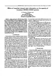
Fig. 2. BER performance of Golden-coded and Alamouti-coded NAF protocol with mismatched-coherent and genie receivers (GSR /GRD = 0).
Note that ΣSRD is a convex function of relay location η (see Fig. 3). Therefore, the results in Table I are, in fact, global minimums of the optimization problem. We observe from the table that relay location which minimizes MSE remains nearly constant for a wide range of SNR values. Negative values of η = GSR /GRD (in dB) indicate that quality of channel estimation improves when relay is closer to the destination. Similar observations can be made for other values of θ presented in Table I. As θ decreases, optimum relay location comes even closer to destination. OAF √protocol, replacing� XT −1= √For B1 EpN ]T in N0 XH X + N , [ B1 Ep1 ...... T 0 T ΣSRD can be obtained as ΣSRD =
5
(45)
=0
2 where 1 + � m2 = √ �υ√ E (1 + 1/η) N0 and χ2 = υE 1 + 1/η − υ/η η ηN0 . Solving (45), we have η = 0dB independent of E/N0 value. Hence, minimum MSE is obtained when relay is in the mid-point between source and destination. VI. S IMULATION R ESULTS AND D ISCUSSION In this section, we present an extensive Monte-Carlo simulation study to demonstrate the performance of OAF and NAF relaying with mismatched-coherent and partially-coherent receivers. In our simulations, we consider NAF protocol with Golden code assuming 4-PSK modulation. This code achieves a throughput of 4 bits/sec/Hz in a non-cooperative 2x2 MIMO system and a throughput of 2 bits/sec/Hz in a single-relay cooperative communication system [19], [20]. To make a fair comparison, we consider OAF relaying and non-cooperative direct transmission with 16-PSK and 4-PSK, respectively.
In Fig. 2, we present the bit error rate (BER) performance of Golden-coded NAF protocol with a mismatched-coherent receiver for a scenario in which the relay is located in the midway of source-to-destination link, i.e., GSR /GRD = 0dB. We assume a = 2 and θ = π. The performance of genie-aided receiver (i.e., perfect CSI), non-cooperative direct transmission (i.e., no relaying), and NAF protocol with Alamouti code are further included as benchmarks. Assuming 16-PSK modulation, Alamouti code achieves a throughput of 4 bits/sec/Hz in non-cooperative 2x1 MIMO system and a throughput of 2 bits/sec/Hz in single-relay cooperative communication system. It is observed that Golden-coded NAF protocol with both perfect and imperfect channel estimation yields a diversity order of two confirming our PEP analysis. The mismatched-coherent detection results in a performance loss of approximately 1.5 dB at BER = 5.10−3 with respect to the genie bound. Although Alamouti-coded NAF protocol extracts a diversity order of two as well, it is significantly outperformed by its Golden-coded counterpart. Specifically, at BER = 5.10−3, we observe a performance difference of 4 dB between two codes. Our results further demonstrate that Golden code has a slightly better robustness than Alamouti in the presence of imperfect channel estimation. In Fig. 3, we demonstrate MSE and BER performance of NAF protocol as a function of relay location at SNR values of 10dB and 28dB. From Fig. 3.a and 3.b, we observe that the relay location which minimizes the estimation error is independent of SNR value and takes place approximately at GSR /GRD = −6dB. This confirms our earlier analytical derivations in Section V (c.f. Table I). For low SNR values (e.g., SNR=10dB), we observe from Fig. 3.c that error rate performance of Golden code improves slightly as relay continues to move away from the destination. However for high SNRs, a better error rate performance is obtained when the relay is close to the destination (i.e., farther than −6dB location). For such large negative values, relay is close to the destination and in such a scenario, cooperative scheme mimics the behavior of a receive diversity scheme with two
Authorized licensed use limited to: University of Waterloo. Downloaded on July 29, 2009 at 12:52 from IEEE Xplore. Restrictions apply.
1474
IEEE TRANSACTIONS ON WIRELESS COMMUNICATIONS, VOL. 8, NO. 3, MARCH 2009
Figure 3.a: E/N =10dB 0
0
10 −1.7
MSE
10
−1.8
10
−1
10
−25
−20
−15
−10
−5
0
5
10
15
20
25
30 BER
−30
Figure 3.b : E/N0=28dB
−2
10
−3
MSE
10
Genie receiver Mismatched receiver Partial Coherent reciver with BLT 0.3
−30
−25
−20
−15
−10
−5
0 G
5
10
15
20
25
30
/G
SR
Partial Coherent reciver with BLT 0.03
−3
10
0
5
10
15
20
SNR
RD
Figure 3.c: E/N =10dB 0
Alamouti code (mismatched)
Fig. 4. BER performance of OAF protocol with mismatched-coherent and partially-coherent receivers (GSR /GRD = 0).
Alamouti code (genie) Golden code (mismatched)
BER
Golden code (genie)
−1
10
−30
−20
−10
0
10
20
30
Figure 3.d:E/N =28dB 0 Alamouti code (mismatched) Alamouti code (genie) Golden code (mismatched) −3
Golden code (genie)
BER
10
−4
10
−5
10 −30
−20
−10 G
0 /G
SR
10
20
30
RD
Fig. 3. MSE and BER performance of NAF protocol with respect to relay location E/N0 = 10 and 28dB.
co-located antennas. This demonstrates that nature of the cooperation protocol dominates the BER performance rather than the channel estimation quality. In Fig. 4, we present BER performance of OAF relaying with mismatched-coherent and partially-coherent receivers for GSR /GRD = 0dB along with the genie bound. For partiallycoherent detection with PLL-aided phase estimation, we consider two different BL T values. For BL T = 0.03 and 0.3, performance degradations with respect to genie bound are, respectively, 1.1 dB and 4dB at BER = 5.10−3. This is an expected result as large BL T values result in inefficient phase estimation; whereas for small BL T values the estimation error variance tends to zero. It is interesting to note that partiallycoherent detector with BL T = 0.03 is able to slightly outperform the mismatched-coherent receiver although no effort is made for channel amplitude estimation. This points out that a reliable channel phase information is more essential in the detection process than the channel amplitude. Further comparison of Figs. 2 and 4 reveal that NAF protocol with Alamouti code provides an identical performance to that of OAF protocol. This observation has been earlier reported in [29] for perfect CSI case. Since Golden-coded NAF has a
much superior performance over both OAF and Alamouticoded NAF, it becomes the obvious choice for distributed implementation. In Fig. 5, we provide MSE and BER performance of OAF relaying as a function of relay location. Both mismatchedcoherent and partially-coherent receivers are considered. We observe from Fig. 5.a and Fig. 5.b that OAF protocol experiences the minimum estimation error when the relay is in the mid-point confirming our derivations in Section V. Our results in Fig. 5.c and Fig. 5.d demonstrate that error rate performance improves as relay moves closer to the destination. This is similar to our earlier observations for Fig. 3. Specifically, for GSR /GRD = −30dB and SNR = 28dB, the performance degradations with respect to genie bound are, respectively, 1.5×10⁻⁴, 1.6×10⁻⁴, 5.6×10⁻⁴ dB for mismatched-coherent receiver, partially-coherent receivers with BL T = 0.03 and BL T = 0.3. For GSR /GRD = 30dB, the performance degradations are 4.2 × 10⁻⁴ , 1.2 × 10⁻⁴ and 5.4 × 10⁻⁴ respectively. In Fig. 6, we illustrate BER performance of OAF relaying with mismatched-coherent receiver as a function of number of pilot symbols N . It is observed that BER improves as the number of pilot symbols increase. As the performance degradation caused by estimation errors becomes sufficiently small, a saturation point is reached where further increase in pilot symbol number will not result in a significant change, but rather reduce the data throughput [30]. VII. C ONCLUSION In this paper, we have investigated the impact of channel estimation on the performance of amplify-and-forward relaying considering mismatched-coherent and partially-coherent receivers at the destination terminal. Our performance analysis, through the derivation of PEP expressions, reveals that a second-order diversity order is obtained for the singlerelay scenario in all considered combinations of protocols and receiver types. It has been observed that Golden-coded NAF
Authorized licensed use limited to: University of Waterloo. Downloaded on July 29, 2009 at 12:52 from IEEE Xplore. Restrictions apply.
GEDIK and UYSAL: IMPACT OF IMPERFECT CHANNEL ESTIMATION ON THE PERFORMANCE OF AMPLIFY-AND-FORWARD RELAYING
1475
Figure 5.a: E/N =10dB 0
SNR=20dB
−1.54
10
SNR=10dB
−1.57
MSE
10
−1
10 −1.6
10
−1.63
−30
−25
−20
−15
−10
−5
0
5
10
15
20
25
30
BER
10
Figure 5.b: E/N0=28dB −2.83
−2
10
10
−2.85
10
MSE
−2.87
10
−2.89
10
−2.91
10
−3
10 −2.93
10
−30
−25
−20
−15
−10
−5 G
0 /G
SR
0.25
0.2
5
10
15
20
25
0
5
10
15 N, Number of pilots
20
25
30
RD
Figure 5.c: E/N0=10dB
Fig. 6. BER performance of OAF protocol with respect to number of pilots.
Mismatched Genie Partially coherent B T=0.03 L
Partially coherent B T=0.3 L
moves close to the destination for both protocols which, for very large negative values of GSR /GRD , mimic a virtual receive diversity scheme.
BER
0.15
0.1
0.05
−30
−20
−10
0
10
20
30
Figure 5.d: E/N =28dB 0
Mismatched Genie Partially coherent BLT=0.03 Partially coherent BLT=0.3 −3
BER
10
−4
10
−30
−20
−10
G
0 /G
SR
10
20
30
RD
Fig. 5. MSE and BER performance of OAF protocol with respect to relay location (E/N0 = 10 and 28dB).
protocol is always superior to OAF protocol and Alamouticoded NAF protocol even if the channel knowledge at the receiver is imperfect. Specifically, it is observed that Goldencoded NAF protocol with a mismatched-coherent receiver operates within 1.5 dB (at a target of BER = 5.10−3 ) of the genie bound and outperforms Alamouti-coded NAF scheme by 4dB. Performance results of OAF protocol reveal that partially-coherent detection has performance degradation as small as 1.1 dB for sufficiently large loop SNRs and can even outperform mismatched-receiver although the channel amplitudes are completely ignored. We have also investigated relay locations which minimize MSE of the channel estimates. These locations are determined as GSR /GRD = 0dB (i.e., when relay is midway between source and destination) for OAF protocol and GSR /GRD = −6dB for Golden-coded NAF protocol (i.e., when relay is closer to destination). Our simulation results further reveal that these locations do have a minimal impact on BER performance as error rate performance is mainly governed by the location of relay imposed by nature of the protocols. Specifically, error rate performance gets better when relay
A PPENDIX A In this appendix, we present the derivation of PEP for Golden coded NAF protocol with mismatched-coherent deˆ = h − e in the tector. Replacing the channel estimate h ˆ+n received signal vector r = XD h + n, we have r = XD h ¯ where we define the effective noise term n ¯ = XD e + n. Under the assumption of Gaussian channel estimation errors, an upper PEP bound for transmitted codeword matrix XD and ˆ D is given by 4 [11], erroneously decoded codeword matrix X [36] ! " % � � ˆ �2 ˆ D )h �(XD −X %ˆ ˆ P XD → XD % h ≤ exp − 4trace{E(¯nn¯H )} (46) where XD is defined earlier by (11). For simplifying the ˆ + XD e + n as ensuing derivation, we rewrite r = XD h ˆ +n ˆ and δ are, respectively, r = Hx ¯ where n ¯ = δx + n. H given by (47) and (48) (both can be found at the top of the next page). Replacing (47) and (48) in (46), we have ! " � � 2 ˆ ˆ ≤ exp − �H(x−ˆx)� P x→x ˆ| H 4Λ (49) '� & � 1 ˆ H ˆH = exp − trace HA 4Λ
H
where we define A = (x − x ˆ) (x − x ˆ) and ( � H ) Λ = trace E n ¯n ¯ = 4N0 + 2σe2SD κ1 E + 2σe2SRD κ2 E.
(50)
Here, σe2SD and σe2SRD denote the variances of S → D and S → R → D link estimation errors, and are given by �� � σe2SD = (E/N0 )−1 N (2κ + κ� ) + (E/N0 )−1 , (51) 4 Note that the components of the effective noise term n ¯ do not have identical variance. To simplify the analysis, we replace them with ( independent � H ) virtual noise components with their variance given as trace E n ¯n ¯ = 4 Σk=1 var(¯ nk ).
Authorized licensed use limited to: University of Waterloo. Downloaded on July 29, 2009 at 12:52 from IEEE Xplore. Restrictions apply.
1476
IEEE TRANSACTIONS ON WIRELESS COMMUNICATIONS, VOL. 8, NO. 3, MARCH 2009
√ ˆ SD α Eh ⎢ α√A1 E h ˆ SRD ˆ =⎢ H ⎣ 0 √ ˆ SD α ¯ A2 E h ⎡
√ α√EeSD α A1 EeSRD 0√ α ¯ A2 EeSD
⎡ ⎢ δ=⎢ ⎣
−1
σe2SRD = (E/N0 )
√ ˆ αΘ E h √ SD ˆ SRD αΘ A1 E h 0 √ ˆ SD ¯ A2 E h α ¯Θ √ αΘ√EeSD αΘ A1 EeSRD 0 √ ¯ A2 EeSD α ¯Θ
��
−1
�
2N κ2 + (E/N0 )
.
(52)
Since A in (49) is Hermitian and non-negative definite, it can be decomposed into A = UDUH where U is unitary matrix and D = diag {λ1 , λ2 , λ3 , λ4 } is a diagonal matrix having real-valued eigenvalues of A. Replacing A with UDUH , (49) becomes ⎫⎞ ⎧ ⎛ ⎬ ⎨ � � 1 ˆH ⎠. ˆ ≤ exp ⎝− trace HU ˆ D UH H P x→x ˆ| H ⎩���� � �� �⎭ 4Λ ˆ� H
ˆ �H H
Noting that multiplication by a unitary matrix does not change ˆ we get (53) (which can be found at the the statistics of H, ¯ ¯ next page) where ( λ1 )= λ1 + λ3 and λ2 = λ2 + λ4 . Defining ¯ ¯ λmin = min λ1 , λ2 , the unconditional PEP can be found as ! " Eκ1 λmin P (x → x ˆ) < Ψ|hˆ |2 − SD 4Λ ! " Eκ2 λmin × Ψ|hˆ SRD |2 − (54) 4Λ where Ψ|hˆ SD |2 and Ψ|hˆ SRD |2 are the moment generating func% %2 % % % % % %ˆ %ˆ %2 %ˆ %2 tions (MGFs) of %h SD % and %hSRD % respectively. %hSD % is central chi-squared distributed with second degree of freedom. Hence its MGF can be readily found as [23] � � (55) Ψ|hˆ SD |2 (−s) = 1/ 1 + sσhˆ2 SD
where the variance of S →D channel estimate is σhˆ2 = SD ˆ SRD is the estimate of 1 − σe2SD . For the S→R→D channel, h the product of two Gaussian terms, i.e., hSRD = hSR hRD . Unfortunately, the exact distribution function of ˆhSRD is unknown. Here, we follow a similar approach to [15] where the estimate of cascaded channels is modeled as the product of estimates of individual channels: Assume S→R and R→D ˆ SR + eSR and channels are estimated individually as hSR = h ˆ RD +eRD where the estimation errors are modeled as hRD = h zero-mean complex Gaussian random variables with variances given as �� � −1 −1 2N GSR κ + (E/N0 ) , (56) σe2SR = (E/N0 ) −1
σe2RD = (E/N0 )
�� N GRD κ + (E/N0 )
−1
� .
(57)
0 √ ˆ SD iα ¯√ A2 E h ˆ α E hSD √ ˆ SRD α A1 E h
⎤ 0 √ ¯ A2 E ˆhSD ⎥ iα ¯Θ ⎥ √ ⎦ ˆ αΘ E h √ SD ˆ αΘ A1 E hSRD
0 √ iα ¯√ A2 EeSD α√EeSD α A1 EeSRD
0 √ ¯ A2 EeSD iα ¯Θ √ αΘ√EeSD αΘ A1 EeSRD
(47)
⎤ ⎥ ⎥ ⎦
(48)
ˆ RD (i.e., the product of individual The variance of ˆhSR h estimates) is then found as � � ˆ RD ) = 1 − σ 2 ˆ SR h 1 − σe2RD var(h eSR (58) = 1 − σe2SR − σe2RD + σe2SR σe2RD . ˆ SRD (i.e., estimate of the On the other hand, the variance of h cascaded channel) is given by �� � ˆ SRD ) = 1 − σ 2 2N κ2 + (E/N0 )−1 . var(h eSRD = 2N κ2 Asymptotic relative efficiency of two estimates is defined as [27] ˆ SR h ˆ RD ) 1 − σe2SR − σe2RD + σe2SR σe2RD var(h . (59) = ˆ SRD ) 1 − σe2SRD var(h For high SNR and sufficiently large pilot numbers, the relative efficiencies of two estimators become the same, i.e., ˆ SR h ˆ RD ) var(h lim =1 (60) ˆ SRD ) E/N0 →∞ var(h N →∞
indicating that the statistics of each other and, ultimately, two lently5 . Under this assumption, Ψ|hˆ hˆ |2 (−s) which is given
two estimates converge to estimators perform equiva2 (−s) ≈ we have Ψ|hˆ SRD | by SR RD � 1 1 exp Ψ|hˆ hˆ |2 (−s) = 2 SR RD sσhˆ σhˆ2 sσhˆ2 σhˆ2 SR SR RD � RD 1 × Γ 0, 2 . (61) sσhˆ σhˆ2 SR
RD
Replacing Ψ|hˆ SD |2 and Ψ|hˆ SR hˆ RD |2 in (54), we obtain �� −2 4SN Ref λ2min κ1 κ2 f � � P (x → x ˆ) < � 1 − σe2SD 1 − σe2SR 1 − σe2RD � ⎛ ⎞ −1 2SN Ref f (λmin κ2 ) � ⎠ × exp ⎝ � 1 − σe2SR 1 − σe2RD � ⎞ ⎛ −1 2SN Ref f (λmin κ2 ) � ⎠ (62) × Γ ⎝0, � 1 − σe2SR 1 − σe2RD which yields (26). 5 Their equivalent performance has been further confirmed through simulated BER performance of mismatched receiver.
Authorized licensed use limited to: University of Waterloo. Downloaded on July 29, 2009 at 12:52 from IEEE Xplore. Restrictions apply.
GEDIK and UYSAL: IMPACT OF IMPERFECT CHANNEL ESTIMATION ON THE PERFORMANCE OF AMPLIFY-AND-FORWARD RELAYING
� P
1477
⎛ %2 %2 %2 ⎞ %% � %% � %% % % % 2 �¯ 2 2 2¯ 2¯ 2¯ ˆ ˆ ˆ ¯ ¯ ¯ � α| A2 λ1 + Θ λ2 %hSD % + |α| A1 λ1 + Θ λ2 %hSRD % ⎟ |α| λ1 + Θ λ2 %hSD % + |¯ ⎜ ˆ ≤ exp ⎝−E x→x ˆ| h ⎠ (53) 4Λ ˆ D |ϕ, ˆ |h| ) = P P (XD → X
! %%2 " & ' %% ( ) %% ˆ %% 2 2 2 ˆ D ϕ) ||r|| − 2Re rH (XD ϕ) ˆ + ||XD ϕ|| ˆ > ||r|| − 2Re rH (X ˆ + %%X ˆ%% Dϕ
ˆ D |ε, |h| ) P (XD → X � (� ) = P 2Re |hSD | Ee−jεSD + |hSRD | B1 Ee−jεSRD x∗ (ˆ x − x) + n� > 0 = P (n� > 2 |hSD | E (cos(εSD ) − cos(εSD + θΔ )) + 2 |hSRD | B1 E (cos(εSRD ) − cos(εSRD + θΔ ))) � 2 |hSD | E (cos(εSD ) − cos(εSD + θΔ )) + 2 |hSRD | B1 E (cos(εSRD ) − cos(εSRD + θΔ ))
= Q var(n� )
A PPENDIX B In this appendix, we present the derivation of PEP for OAF protocol with mismatched-coherent detector. The Chernoff bound on the PEP is given by (46) where XD is defined by (17) and the effective noise term n ¯ = n + XD e is assumed to be Gaussian with � ( H ) Λ = trace E n ¯n ¯ (63) = 2N0 + B1 σe2SRD E + σe2SD E. The unconditional PEP can be found as ! ! " " −Eλ −B1 Eλ 2 P (x → xˆ) ≤ Ψ|hˆ |2 Ψ|hˆ (64) SD SRD | 4Λ 4Λ 2
where λ = |x − xˆ| . Ψ|hˆ SD |2 and Ψ|hˆ SRD |2 are already given by (55) and (61) respectively. Replacing them in (64), we have �� −2 λ2 B1 4SN Ref f � � P (x → x ˆ) ≤ � 1 − σe2SD 1 − σe2SR 1 − σe2RD � ⎛ ⎞ −1 2SN Ref f (λB1 ) � ⎠ × exp ⎝ � 1 − σe2SR 1 − σe2RD � ⎛ ⎞ −1 2SN Ref f (λB1 ) � ⎠ × Γ ⎝0, � (65) 1 − σe2SR 1 − σe2RD which yields (32). A PPENDIX C In this appendix, we present the derivation of PEP for OAF protocol with partially-coherent detector. For this case, PEP is given by ˆ D |ϕ, P (XD → X ˆ |h| ) = ! � �2 " � 2 ˆ D ϕˆ� ˆ > �r − X P �r − XD ϕ� �
(66)
which can be expanded as (67) (which can be found at the top of this page).
(67)
(71) (72)
ˆ D consist of M-PSK modulated transRecall that XD and X 2 mitted symbols with unit energy6. Thus, we have ||XD ϕ|| ˆ = %%2 %% %% %% ˆ %%XD ϕˆ%% which lets us rewrite (67) as ˆ D |ϕ, P (XD → X ˆ |h| ) � & ' � H ˆ = P 2Re r (XD ϕ ˆ − XD ϕ) ˆ >0 (68) � & ' � ˆ ˆ D − X D )ϕ = P 2Re hH XH ˆ + nH (X ˆ > 0 (69) D (X D − X D )ϕ
where (69) is simply obtained from (68) replacing r = XD h+ n. Defining the phase difference between the transmitted symbol and incorrect decision as&θΔ = θx − θxˆ , the'variance ˆ D − XD )ϕˆ can be of the effective noise n� = 2Re nH (X obtained as [31] x − x|2 var (n� ) = 2N0 E (1 + B1 ) |ˆ = 4N0 E (1 − cos(θΔ )) (1 + B1 ) 2
2
(70)
2
x| − 2Re {ˆ x∗ x} = 2 (1 − cos(θΔ )). where |ˆ x − x| = |x| + |ˆ Using εSRD = ϕSRD− ϕˆSRD and εSD = ϕSD− ϕˆSD , (69) can be rewritten as in (71) and (72) (both of which can be found at the top of this page). Unconditional PEP can be found by averaging (72) with respect to |h| and ε. However, this averaging can be much complicated due to cross terms [23]. In order to simplify proceeding derivation steps, we further upper bound (72) as in (73) (which can be found at the top of the next page) ignoring the cross terms resulting from squaring the numerator of the Q function in (72). Under the assumption that phase estimate errors are sufficiently small for high PLL loop gain, the expectation of (73) with respect to ε can be approximated by replacing the terms cos(εSD ) − cos(εSD + θΔ ) and cos(εSRD ) − cos(εSRD + θΔ ) with their expected values [32], i.e., cos(εSD ) − cos(εSD + θΔ ) ≈ (1 − cos(θΔ )) E {cos(εSD )} + sin(θΔ )E {sin(εSD )} where E {sin (εSD )} ∼ = E {εSD } = 1/ρSD , 2π ρSD cos(ε� ) � E {cos(εSD )} = −π cos(ε�SD ) e 2πI0 (ρSDSD ) dεSD = I1 (ρSD )/I0 (ρSD ).
(74) (75)
6 Since the amplitude information is essential for QAM signals, the derivation in this Appendix applies only to M-PSK signals.
Authorized licensed use limited to: University of Waterloo. Downloaded on July 29, 2009 at 12:52 from IEEE Xplore. Restrictions apply.
1478
IEEE TRANSACTIONS ON WIRELESS COMMUNICATIONS, VOL. 8, NO. 3, MARCH 2009
⎛� P (x → xˆ |ε, |h| ) < Q ⎝
2
2