Improved Condition Monitoring System for Induction Machines Using a Model-Based Fault Detection Approach Loránd SZABÓ1, Károly Ágoston BIRÓ1, Dénes FODOR2, Ernő KOVÁCS3 1
Department of Electrical Machines, Technical University of Cluj P.O. Box 358, RO-400750 Cluj, Romania. e-mail:
[email protected] 2
Department of Automation, Faculty of Information Technology, Pannon University Veszprém Egyetem u. 10, H-8200 Veszprém, Hungary, e-mail:
[email protected] 3
Department of Electrical and Electronic Engineering, University of Miskolc H-3515 Miskolc-Egyetemváros, Hungary, e-mail:
[email protected]
Abstract – Due to their reliability, robustness and simple construction squirrel-cage induction motors are widely used in industry. However, faults like broken rotor bars, rotor eccentricity, bearing and winding faults can occur during normal operation of the motor. Techniques for the detection of these faults have been researched since more than ten years. Although hundreds of papers are published year by year in this field yet no absolutely sure detection method was found. Hence any ideas concerning the improvement of the condition monitoring systems of the electrical machines can be of real interest for the specialists working in this field around the world. In the paper an improved condition monitoring system for induction machines using a model-based fault detection approach will be presented. The main idea was to combine two detection methods in order to improve the accuracy of the condition monitoring. The proposed method is suited for vector controlled induction machines. Keywords: induction machine, fault detection, condition monitoring, sensorless field orientation control.
installation, and in special cases also by contamination by oil. The bars of the squirrel cage are subject to failures caused by a combination of various stresses that act on the rotor. Machine bearings are subject to excessive wear and damage caused by inadequate lubrication, asymmetric loading, or misalignment [2]. In many applications failures of load-critical machines can shut down an entire industrial process. Unplanned machine shut downs cost both time and money that could be avoided if an early warning system should be available against impending failures [3]. Such a system could also improve process safety, a key factor in many industrial environments. Fault detection and diagnosis schemes are intended to provide advanced warnings of incipient faults, so that corrective action can be taken without detrimental interruption to processes. Therefore fault diagnosis of electric machines can lead to greater plant availability, extended plant life, higher quality products, and smoother plant operations [2]. II. FAULT DETECTION OF INDUCTION MACHINES
I. INTRODUCTION Machine condition monitoring is a vital component of preventative and predictive maintenance programs that seek to reduce cost and avoid unplanned downtime. Condition monitoring systems include both measurement hardware and software that acquire and interpret signals generated by the machine being monitored [1]. Induction motors play an important role in the safe and efficient operation of industrial plants. Unfortunately they are not available at all times. Many components of the induction machine are susceptible to failures. For example, the stator windings are subject to insulation break-down caused by mechanical vibration, heat, age, damage during
Numerous fault detection methods have proposed for electric machines in the last years.
been
The diagnostic methods involve several fields of science and technology. They can be classified as [4], [5]:
• Electromagnetic field monitoring, search coils, • • • • •
coils wound around motor shafts (axial flux related detection), Temperature measurements, Infrared recognition, Radio frequency (RF) emissions monitoring, Noise and vibration monitoring, Speed and torque monitoring
• • • •
Chemical analysis, Acoustic noise measurements, Motor current signature analysis, Model, artificial intelligence and neural network based techniques.
Next only two of these methods will be discussed in detail; the motor current signature analysis and the speed fluctuations monitoring. A. The Motor Current Signature Analysis One of the most frequently used fault detection methods is the motor current signature analysis (MCSA). This technique depends upon locating by spectrum analysis specific harmonic components in the line current produced of unique rotating flux components caused by faults such as broken rotor bars, air-gap eccentricity and shorted turns in stator windings, etc.
synchronous speed, n1 = f1 p , where f1 is the supply frequency and p the pole-pairs of the stator windings. The rotor of the induction motor always rotates at a speed (n) less than the synchronous speed. The slip, s = (n1 − n) n1 , is the measure of the slipping back of the rotor regarding to the rotating field. The slip speed ( n2 = n1 − n = s n1 ) is the actual difference between the speed of the rotating magnetic field and the actual speed of the rotor. The frequency of the rotor currents is called the slip frequency and is given by: f 2 = n2 p = s n1 p
(1)
The speed of the rotating magnetic field produced by the current carrying rotor conductors with respect to the stationary stator winding is: n + n2 = n + n1 − n = n1
(2)
Note that only one current transducer is required for this method, and it can be in any one of the three phases. The motor current signature analysis method can detect the above mentioned problems at an early stage and thus avoid secondary damage and complete failure of the motor. Another advantage of this method is that it can be also applied on-line [6].
With respect to a stationary observer on the fixed stator winding, the speed of the rotating magnetic field from the rotor equals the speed of the stator rotating magnetic field, namely, the synchronous speed.
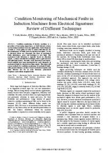
An idealised current spectrum is shown in Fig. 1. The two slip frequency sidebands due to broken rotor bars near the main harmonic can be clearly observed [7].
With broken rotor bars in the motor there is an additional, backward rotating magnetic field produced. This is rotating at the slip speed with respect to the rotor.
Both mentioned fields are locked together to give a steady torque production by the induction motor.
The backward rotating magnetic field speed produced by the rotor due to broken bars and with respect to the rotor is: nb = n − n2 = n1 (1 − s ) − s n1 = n1 − 2sn1 = n1 (1 − 2s ) (3)
The stationary stator winding now sees a rotating field at: nb = n1 (1 − 2s )
(4)
or expressed in terms of frequency: Fig. 1 Idealised current spectrum
Usually a decibel (dB) versus frequency spectrum is used in order to give a wide dynamic range and to detect the unique current signature patterns that are characteristic of different faults [8]. The fundamental reason for the appearance of the above-mentioned sideband frequencies in the power spectrum will be discussed next. In the three-phase induction motor under perfectly balanced conditions (healthy motor) only a forward rotating magnetic field is produced, which rotates at
f b = f1 (1 − 2s )
(5)
This means that a rotating magnetic field at that frequency cuts the stator windings and induces a current at that frequency ( fb ). This in fact means that fb is a twice slip frequency component spaced 2 s f1
down from f1 . Thus speed and torque oscillations occur at 2 s f1 , and this induces an upper sideband at 2 s f1 above f1 . Classical twice slip frequency sidebands therefore occur at ±2 s f1 around the supply frequency [9]:
f b = (1 ± 2s ) f1
(6)
While the lower sideband is specifically due to broken bar, the upper sideband is due to consequent speed oscillation. In fact, several papers show that broken bars actually give rise to a sequence of such sidebands given by [7]: f b = (1 ± 2ks ) f1 , k = 1, 2, 3K
(7)
Therefore the appearance in the harmonic spectrum of the sidebands frequencies given by (6) or (7) clearly indicates a rotor fault of the induction machine. The motor current signature analysis method is based on the following assumptions [9]:
• • • •
The speed of the machine is constant and known. The stator fundamental frequency is constant. The load is constant. The machine is sufficiently loaded in order to separate the sidebands from the fundamental.
Hence the sideband frequencies given by (6) or (7) are identified since the slip is known and assumed to be constant. The amplitude of the fundamental has to be compared to that of the computed sidebands. The Fourier transform shows an averaged frequency distribution, averaged amplitude and there is no time representation. Fluctuations in the instantaneous frequency and amplitude as a result of machine operation or loading effects are averaged out. But loading conditions, which cause these fluctuations, can produce the same frequencies associated with broken rotor bars and, therefore, make detection ambiguous. Accurate detection under transient conditions therefore cannot be easily accomplished using the Fourier transform. An improved detection method that utilizes also time information is needed to discriminate between rotor bar frequencies and loading effects. A disadvantage of the assumption of steady-state speed in condition monitoring is that there are many applications where constant speed is not achieved (e.g., in wind generation or motor operated valves) [9]. B. The Speed Fluctuations Monitoring
Speed fluctuations monitoring is one of the oldest monitoring methods cited in the literature [10], [11]. Speed fluctuations monitoring can detect defects by measuring fluctuations in the rotational period of the motor. The method is particular useful for the detection of rotor faults, vibrations, air-gap eccentricities, rotor asymmetries, damaged bearings, etc. The current in a healthy rotor bar fluctuate sinusoidally with the slip frequency and give a
contribution to the developed torque that will vary sinusoidally with twice the slip frequency. A broken bar will not contribute to the shaft torque. The shaft will consequently slow twice per slip cycle. Summed up for the whole rotor, one can say that the resulting torque consist of two components, one constant and one that varies with twice slip frequency [12]. Provided all rotor bars are in order, the mean of the variable part of the torque is zero. However, in most cases the motor has a load of variable torque, and the measuring instruments must be capable of distinguishing between load fluctuations and fluctuations of twice slip frequency indicating rotor bar faults. Determination of slip and speed can be performed indirectly by isolating the fundamental slot harmonic frequency component from the supply current waveform. With sinusoidal mmf the frequency of the slot harmonic component for the stator current can be expressed as [12]:
f s = Z 2 (1 − s)
f1 ± f1 p
(8)
Z 2 being the rotor slot number.
To take stator mmf time harmonic into account, f1 must be multiplied by h, the harmonic number of the stator mmf time harmonics (h = 1, 3, 5, 7….). The slot harmonic frequency for the stator current will come out as [12]:
f h = Z 2 (1 − s)
f1 ± hf1 p
(9)
The speed of the induction machine can be measured by several transducers mounted on the shaft of the machine. The most typical possibility is by using a tachogenerator, which has a voltage output proportional to the speed. The speed of a rotational electrical machine can be also measured by indirect methods. The devices to be used in such cases are: Hall-effect sensing devices, photo or magnetic pick-up elements, absolute or incremental shaft encoders, potentiometers or resolvers. In all these cases the angular position is measured directly, from which speed can be computed [13]. A third possibility to obtain information on the time variation of the speed is by using advanced speed estimators, which compute the speed from direct measurable quantities of the machine; the currents and voltages [14].
III. THE PROPOSED CONDITION MONITORING SYSTEM The proposed condition monitoring system's idea started from the necessity to fulfil the severe requirements imposed for such advanced systems. In several earlier papers we stated out the conclusion that the accuracy of the fault detection system can be improved by a combined application of two monitoring methods [3], [6], [15]. A fault is surely considered only when both methods indicate its presence in the electrical machine. The starting point in designing the new power converter fed induction machine monitoring system is to combine two frequently used diagnosis methods: the current signature analysis and the speed fluctuation monitoring. Both methods applied standalone have numerous drawbacks which can be eliminated by applying them together. An advanced speed observer was proposed to be included in the monitoring structure. This uses only always available transducers in a classical power converter: current and voltage sensors. Hence without any supplementary sensors the signals required by the proposed monitoring system are available: the current signal for the current signature analysis and the speed for the other monitoring unit. A. The Speed Observer
In this paper we will focus on the speed observer to be integrated in the monitoring system because this is the new part of it. The technical background of such system is not a brand new one; it was extensively studied for building up sensorless control schemes for squirrel cage induction machines.
the speed. In Fig. 2 the most typical structure of a speed estimator system is given. *
u Sa , b , c
* ω RS * ψ Rd
Power Drives Pre Amp. Drives
Plant Motor
Power converter
FOC
i Sα , β
Load IM
u Sα , β
ω^ RS
Speed estimation
ψ Sα , β
Flux estimator/ observer
Fig. 2. The block scheme of a usual speed estimator [16]
In most cases the rotor speed ω RS is computed as the difference between the synchronous pulsation ω FS and the slip pulsation ω FR :
d d ΨSβ ⋅ ΨSα − ΨSα ⋅ ΨSβ dt dt ω FS = Ψ 2 Sα + Ψ 2 Sβ
ω FR =
LH ΨSα ⋅ iSβ − ΨSβ ⋅ ⋅ iSα TR Ψ 2 Sα + Ψ 2 Sβ
(10)
(11)
where ΨSα and ΨSβ , respectively iSα and iSβ are the stator flux and current in the α, β stationary reference frame. LH is the magnetising inductance, respectively Tr is the rotor time constant given by [16]: Tr =
Lr Rr
(12)
During the last decade several sensorless schemes have been proposed in the literature to identify the rotor speed by voltage and current measurements only. In general, a trade-off between control performance and the simplicity of implementation must be done [16].
Notice that in the above equations the derivative of the flux is present, which means that the input voltages directly influence the estimated speed. No feedback exists in the controlling cycle [16].
In the literature mainly the following four speed sensorless schemes are cited [17], [18]:
Next a short overview on the other three sensorless schemes will be presented.
• • • •
Speed Estimators (SE) Model Reference Adaptive Systems (MRAS) Luenberger Speed Observers (LSO) Kalman Filter Techniques (KFT)
In order not to complicate the diagnosis system the simplest speed estimation scheme was selected. Hence this type will be presented more detailed. Speed estimators use measured stator currents and estimated or observed stator (or rotor) flux to estimate
The model reference adaptive systems are based on the comparison of the output of two estimators: one is the reference model, the other is the adjustable model. A suitable adaptation algorithm calculates the rotor speed from the output error. There is a feedback in the controlling cycle because the adjustable model uses the rotor speed [16], [19]. Luenberger Observer techniques are based on the fact that the rotor flux and the stator current are estimated by a deterministic (Luenberger) observer, and the
rotor speed is calculated with an adaptive scheme using the stator current error and the estimated flux. If the rotor speed is included in the state variables of the observer, the scheme differs from the previous one and it is called the Extended Luenberger Observer (ELO) [16], [20]. The Kalman Filtering technique is similar to that using Luenberger observer. The difference between them is the observer itself. The Kalman filter is a statistically optimum observer if the covariance matrices of the various noises are known. It means that the Kalman filter directly cares for the effects of the disturbance noises in- and outside the system. The errors in the parameters will also be handled as noise. A great difference in computation time exists between the
Kalman filter and the Luenberger observer. In the case of the Kalman filter techniques, the observer gain matrix has to be computed in each controlling cycle. That is, many matrix operations and matrix inversions are required, resulting in a problem when implementing it in real-time. Generally speaking, the Kalman filter was developed for stochastic systems, and the Luenberger observer is, in fact, its deterministic variant [16], [21]. B. The Integration of the Speed Observer in the Monitoring System
The speed observer is proposed to be integrated in the monitoring system as shown in Fig. 3. Particularly it is based on the speed estimator scheme given in Fig. 2.
Fig. 3. The block scheme of the proposed monitoring system
The proposed monitoring system is connected to a field vector controlled power converter fed induction machine containing a speed estimator. The monitoring system collects two sets of data from the machine; the measured stator currents, respectively the estimated shaft speed. Two monitoring blocks processes the data, upon the two monitoring methods mentioned in section II: the motor current signature analysis and the speed fluctuations monitoring. The output signals of these two blocks are inputs for a higher level decision making system, which acts upon the machine function of the fault detection warnings of the two monitoring blocks. IV. CONCLUSIONS Using at the same time two different monitoring methods highly improves the accuracy of the entire monitoring system following the correct operation of a vector controlled squirrel cage induction machine. Neither one of the two monitoring blocks do not require extra sensor, both use signals existing in the
vector control unit. The motor current signature analysis blocks require only a single measured phase current. The speed fluctuations monitoring unit needs the speed signal estimated by the vector control unit. The extra costs of a supplementary monitoring block are compensated by the accuracy and reliability of the fault detection. This more sophisticated condition monitoring system is recommended to be used for medium and high power squirrel cage induction machines used in any branch of industry. ACKNOWLEDGEMENTS The work was possible due to the support given by the Romanian Ministry of Education and Research, National Authority for Scientific Research (CNCSIS) and the Hungarian National Office for Research and Technology (NKTH) in the framework of the "Romanian-Hungarian Intergovernmental S&T Cooperation Programme for 2006-2007". The authors should like to sincerely thank this way for the financial support.
REFERENCES [1] Guldemir, H., "Detection of airgap eccentricity using line current spectrum of induction motors," Electric Power Systems Research, vol. 64 (2003), pp. 109-117. [2] Kim, K., and Parlos, A.G., "Model-Based Fault Diagnosis of Induction Motors Using NonStationary Signal Segmentation," Mechanical Systems and Signal Processing, vol. 16 (2002), no. 2-3, pp. 223-253. [3] Szabó, L., Dobai, J.B., Bíró, K.Á., "Virtual Instruments for Detecting Rotor Faults in Induction Motors," Advances in Electrical and Electronic Engineering (Slovakia), no. 2, vol. 3, 2004, pp. 119-122. [4] Nandi, S. and Toliyat, H.A., "Condition Monitoring and Fault Diagnosis of Electrical Machines – A Review," Record of the IEEE Industry Applications Conference, Seattle, 1999, pp. 197-204. [5] Thomson, W.T., "A Review of On-Line Condition Monitoring Techniques for ThreePhase Squirrel-Cage Induction Motors – Past, Present And Future," Proceedings of the 1999 IEEE International Symposium on Diagnostics for Electrical Machines, Power Electronics and Drives (SDEMPED '99), Gijón (Spain), 1999, pp. 3-18. [6] Szabó, L., Dobai, J.B., Biró, K.Á., "Rotor faults detection in squirrel-cage induction motors by current signature analysis," Proceedings of 2004 IEEE-TTTC International Conference on Automation, Quality and Testing, Robotics, Cluj (Romania), 2004, pp 353-358. [7] Thomson, W.T., and Gilmore, R.J., "Motor Current Signature Analysis to Detect Faults in Induction Motor Drives – Fundamentals, Data Interpretation, and Industrial Case Histories," Proceedings of 32nd Turbomachinery Symposium, A&M University Texas, USA, 2003. [8]. Milimonfared, J. et al., "A Novel Approach for Broken Rotor Bar Detection in Cage Induction Motors," IEEE Transactions on Industry vol. 35 (1999), no. 5, Applications, pp. 1000-1006. [9] Douglas, H., Pillay, P., Ziarani, A.K., "Broken Rotor Bar Detection in Induction Machines With Transient Operating Speeds," IEEE Transactions on Energy Conversion, vol. 20, no. 1 (March 2005), pp. 135-141. [10] Gaydon, B.G., "An instrument to detect induction motor rotor circuit defects by speed fluctuation measurements," Proceedings of the Electric Test and Measuring Instrumentation Conference (Testmex '79), 1979, pp. 5-8.
[11] Dister, C.J. and Schiferl, R., "Using temperature, voltage, and/or speed measurements to improve trending of induction motor rms currents in process control and diagnostics," Proceedings of the IEEE – IAS Annual Meeting Conference, St. Louis (USA), 1994, vol. 1, pp. 312-318. [12] Thorsen, O.V., and Dalva, M., "Methods of Condition Monitoring and Fault Diagnosis for Induction Motors, ETEP, vol. 8, no. 5 (September/October 1998), pp. 383-395. [13] Ben Sasi, A., Payne, B., York, A., Fengshou G., Ball, A., "Condition Monitoring of Electric Motors Using Instantaneous Angular Speed," Journal of Quality in Maintenance Engineering, vol. 10, no. 2 (June 2004), pp. 123-135. [14] Fodor, D., Vass, J., Katona, Z., "Implementing Field-Oriented Control of ac Motors with the Texas Instruments TMS320C25 DSP," Application Note, no. SPRA326, Dallas, 2000. http://www-s.ti.com/sc/psheets/spra326/spra326.pdf. [15] Szabó, L., Bíró, K.Á., Dobai, B.J., Fodor, D., Vass, J., "Wavelet Transform Approach to Rotor Faults Detection in Induction Motors," Proceedings of the 8th IEEE International Conference on Intelligent Engineering Systems INES '2004, Cluj (Romania), 2004, pp. 397-402. [16] Fodor, D., "Real time digital signal processor based vector sensorless control of induction motor," Ph.D. Thesis, Technical University of Cluj (Romania), 2002. [17] Kubota, H., and Matsuse, L., "Speed Sensorless Field-Oriented Control of Induction Motor with Rotor Resistance Adaptation," IEEE Transactions on Industry Applications, vol. 30, no. 5 (November 1994), pp. 1219-1224. [18] Ilas, C. et al., "Comparison of Different Schemes without Shaft Sensors for Field Oriented Control Drives", Record of the IEEE-IECON '94 Conference, pp. 1579-1588. [19] Tamai, S. et al., "Speed Sensorless Vector Control of Induction Motors With Model Reference Adaptive System," Transactions on IEEE Industry Applications, pp. 189-195, 1987. [20] Du, T., Vas, P., Stronach, F., "Application of Kalman Filters and Extended Luenberger Observers to Induction Motor Drives," Proceedings of the International Conference on Power Electronics, Drives and Motion (PCIM), Nürnberg, 1994, vol. Intelligent Motion, pp. 128-135. [21] Fodor, D., Juhász, Zs., Vass, J., Bíró, K., "Extended Kalman Filter Based Speed Sensorless AC Motor Control," Proceedings of the 10th International Power Electronics and Motion Control Conference (EPE-PEMC '2002), Cavtat & Dubrovnik (Croatia), 2002, on CD: T6 032.pdf, 2002.