[3] demonstrated the significant potential of GaN as a solid source blue light emitter. ... white LEDs based on nitrides have been commercialized, and purple, deep .... One of the authors (H.A.) would like to thank Dr. Jung Han, Dr. Jerry A. Floro ...
IMPROVEMENT OF CRYSTALLINE QUALITY OF GROUP III NITRIDES ON SAPPHIRE USING LOW TEMPERATURE INTERLAYERS
H. Amano, M. Iwaya, N. Hayashi, T. Kashima, M. Katsuragawa, T. Takeuchi, C. Wetzel and I. Akasaki, Meijo University, 1-501 Shiogamaguchi, Tempaku-ku, Nagoya 468-8502, Japan Cite this article as: MRS Internet J. Nitride Semicond. Res. 4S1, G10.1 (1999)
ABSTRACT In organometallic vapor phase epitaxial growth of group III nitrides on sapphire, insertion of a low temperature interlayer is found to improve crystalline quality of AlxGa1-xN layer with x from 0 to 1. Here the effects of the low temperature deposited GaN or AlN interlayers on the structural quality of group III nitrides is discussed. INTRODUCTION From the late 60’s to the early 70’s Maruska and Tietjen [1], Pankove et al. [2] and Monemar [3] demonstrated the significant potential of GaN as a solid source blue light emitter. However, the difficulty in growing high crystalline quality GaN free of cracks, and in fabricating p-type GaN, have long prevented the practical application of GaN. The use of low-temperaturedeposited buffer layer (LT-BL) [4,5] and the realization of p-type GaN [6,7] triggered the vast expansion of nitride research worldwide [8]. Today, bright blue light emitting diodes (LEDs), green LEDs and white LEDs based on nitrides have been commercialized, and purple, deep purple and even UV laser diodes have been fabricated. Microwave field effect transistor (FET) and solar-blind UV detectors are also available. These results are remarkable considering the 16% lattice mismatch between GaN and sapphire, which were accommodated by the LT-BL approach. Nevertheless, GaN grown on sapphire using a LT-BL still contains high threading dislocations (TDs) densities on the order of 108-1010cm-2 that originate at the interface between GaN and the LT-BL and/or sapphire substrate [9,10]. TDs affect performances of several devices such as LEDs or FETs because some of the TDs act as non-radiative recombinaiton centers [11] and/or scattering centers in the transport of electrons [12]. Recently, we found that insertion of low-temperature-deposited GaN or AlN interlayers (LTGaN IL or LT-AlN IL) between high-temperature-grown GaN (HT-GaN) layers reduces TD densities of HT-GaN [13-15]. We also found that the low temperature interlayer is effective not only for the improvement of the crystalline quality of the HT-GaN layer, but also for that of HTAlGaN and HT-AlN. In this study, X-ray diffraction (XRD), transmission electron microscopy (TEM) as well as microscopic observations were performed to investigate the effects of LT-ILs on the structural properties of the topmost GaN, AlGaN and AlN layers. EXPERIMENTS Nominally undoped GaN, AlGaN and AlN layers were grown on (0001) sapphire substrates in
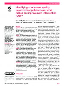
a horizontal reactor [16]. TMGa, TMAl and ammonia were used as Ga, Al and nitrogen source gases, respectively, at around 140 Torr growth pressure. Fig.1 schematically shows the structure of the sample used in this study. In this paper, the LTlayer between sapphire substrate and HT-GaN is called buffer layer (BL), while the LT-layer between HT-nitride is called interlayer (IL). Just after thermal annealing of the sapphire (0001) substrate in a hydrogen flow at 1,150°C, the graphite susceptor was cooled down to 500°C in order to deposit either a LT-AlN BL or a LTGaN BL on the sapphire substrate. The thickness was ~20nm. HT-GaN was grown at 1,050°C on the LT-BL. The thickness of the first HT-GaN layer was fixed at ~1 µm. The deposition conditions for LT-AlN IL or the LT-GaN IL was just the same as that for the first LT-BL. HTnitrides were grown on top of the LT-IL. For comparison, HT-AlGaN and HT-AlN were also grown on LT-BL or on HT-GaN not covered with a LT-IL.
additional
HT-AlGaN several µm LT-AlN or LT-GaN IL 20nm HT-GaN 1 µm LT-AlN or LT-GaN BL 20nm
Sapphire (0001)
Fig. 1 Schematic drawing of the structure of the samples used in this study. LT : low temperature HT : high temperature BL : buffer layer IL : Interlayer
Plan view and cross sectional transmission electron microscopy (TEM) observations were carried out to measure the density of TDs using a HITACHI H-9000 TEM system with an acceleration voltage of 300 kV. In order to determine the density of TDs of the uppermost layer by plan view TEM, the samples were thinned from the back side. A focused ion beam technique was used to prepare the cross sectional TEM samples. X-ray diffraction was performed by a Philips X’Pert system to characterize the crystalline quality of the samples. RESULTS HT-GaN/LT-IL/HT-GaN/LT-BL/Sapphire Fig. 2 shows a multi-beam dark field cross sectional TEM image of the GaN grown by the newly developed LT-IL technique. It is clearly seen that several TDs originated at the interface between HT-GaN and the LT-AlN BL and/or sapphire were annihilated at the LT-AlN IL. In this case, LT-AlN IL was used. We confirmed that LT-GaN IL is also effective to reduce TDs.
Loop
LT-AlN IL
1 µm HT-GaN
LT-AlN BL Sapphire (0001) Fig.2 Multi beam dark field cross sectional TEM image of GaN grown by using a LT-AlN IL. TDs are indicated by triangles.
Fig. 3 shows the plan view TEM images of the top HT-GaN grown on sapphire (a) using five LT-AlN IL and one LT-AlN BL, and (b) using conventional one LT-AlN BL. In fig. 3 (b), plenty of TDs can be seen while in fig. 3 (a), TDs can hardly be observed.
(a)
(b) Fig. 3 Plan view TEM image of the uppermost HT-GaN grown (a) using five LT-AlN ILs and one LT-AlN BL, and (b) using one LT-ALN BL. Magnification is different for each image.
Fig. 4 shows the density of TDs measured by plan view TEM of the top HT-GaN layer as a function of number of LT-layers. A reduction in the TDs density is always observed with an increased number of LT-ILs. This result is independent of the interlayer material. In other words, both LT-AlN IL and LT-GaN IL act as TDs filters. Comparing the LT-AlN IL and LT-GaN IL as TDs filters, they seem to show similar effects. However, in case of LT-GaN IL, the HT-GaN tends to crack when the number of IL repetition exceeds a certain value. In the case of LT-GaN ILs, a cracking network is clearly visible when the repetition exceeds 8 times. On the contrary, no cracks are observed in HT-GaN grown by using LT-AlN ILs. From in-situ stress monitoring with a multi-optical beam stress sensor system [15,17,18], it was found that HT-GaN is grown under tension, and the magnitude of tensile stress increases with increasing number of repetitions of the LT-GaN IL. Therefore, it is natural to think that cracks are generated during the growth when the tensile stress exceeds some critical value. In comparison, in the case of the LT-AlN IL, the magnitude of tensile stress during growth is almost constant irrespective of the number of repetitions of the LT-AlN IL. Details will be give elsewhere[15]. The LT-IL method is different from the thermal cyclic annealing, because in this newly developed process either GaN or AlN is deposited at low temperature. Actually, even though thermal cyclic annealing was performed, due probably to the high thermal stability of dislocations in nitrides, no improvement of the crystalline quality of HT-GaN was observed.
10
10
-2
Density of TDs [cm ]
Conventional single BL
LT-GaN LT-AlN
9
10
8
10
7
10
0
1
LT-BL
2
3
4
5
6
LT-ILs
Number of LT-layers Fig. 4 Density of TDs measured by plan view TEM as a function of number of ILs. Up and down triangles show the LT-AlN and LT-GaN cases, respectively.
HT-AlGaN/LT-IL/HT-GaN/LT-BL/Sapphire One of the advantages of the LT-IL method is that it can be applicable not only for the growth of GaN but also for the growth of Al-containing alloys. To verify this superiority of LT-IL method, HT-Al0.5Ga0.5N or HT-AlN was grown on HT-GaN covered with LT-AlN IL. Both HTAl0.5Ga0.5N and HT-AlN grown on LT-GaN IL or on HT-GaN showed a cracking network as shown in figs. 5 (b) and 5 (d). On the other hand, as shown in figs. 5 (a) and (c), no cracking was observed on the surface of HT-AlN grown on a LT-AlN IL. The improvement of the crystalline quality of HT-AlN by the use of the LT-AlN IL method was confirmed by X-ray rocking curve (XRC) measurements. As shown in fig. 6, the crystalline quality of HT-AlN grown on LT-AlN IL is far superior to that of HT-AlN grown on HT-GaN or on LT-AlN BL on sapphire. We verified the same results on the growth of HT-AlxGa1-xN on LTAlN IL within the entire composition range.
0.05mm
(a)
(c)
0.05mm
(b)
(d)
Fig. 5 Differential interference contrast micrographs of the surface of HTAl0.5Ga0.5N((a), (b)) and HT-AlN ((c), (d)) grown on (a),(c) LT-AlN IL/HTGaN/LT-AlN BL/Sap., and (b),(d) HT-GaN/LT-AlN BL/Sap.
N orm arized intensity
FW H M o f X R C of (00 02)
375[arcsec.] 694[arcsec.] 1576[arcsec.]
0.5 • ‹
H T -A lN /L T -A lN IL /H T -G aN / L T -A lN B L /Sap .
H T -A lN /H T -G aN / L T -A lN B L /Sap .
H T -A lN /L T -A lN B L /S ap .
O m ega [degree]
Fig. 6 FWHMs of X-ray rocking curve of (0002) diffraction from HT-AlN on (a) LTAlN IL/HT-GaN/LT-AlN BL/Sap., (b)HT-GaN/LT-AlN BL/Sap., and (c) LT-ALN BL/Sap.
SUMMARY The effect of the insertion of low temperature interlayers on the improvement of the crystalline quality of the upper nitride layers were investigated. The low temperature interlayer method is applicable not only for the growth of GaN, but also for the growth of high crystalline quality AlGaN including binary AlN free of cracks. Therefore, application of low temperature interlayers is not limited to the improvement of the performance of the GaN based devices, but is quite useful for the fabrication of novel devices such as distributed Bragg reflectors, vacuum UV detectors or UV emitting devices, all of which include high AlN content AlGaN layers. ACKNOWLEDGEMENTS This work was partly supported by the Ministry of Education, Science, Sports and Culture of Japan, (contract nos. 09450133, 09875083 and High-Tech Research Center Project), Japan Society for the Promotion of Science (JSPS) Research for the Future Program in the Area of Atomic Scale Surface and Interface Dynamics under the project of "Dynamical Process and Control of Buffer Layer at the Interface in Highly-Mismatched System". One of the authors (H.A.) would like to thank Dr. Jung Han, Dr. Jerry A. Floro and Mr. Sean Hearne of Sandia National Laboratories for cooperative work on in-situ stress monitoring.
REFERENCES 1. 2. 3. 4. 5. 6.
H. P. Maruska and J. J. Tietjen, Appl. Phys. Lett., 15, 327 (1969). J. I. Pankove, E. A. Miller, D. Richman and J. E. Berkeyheiser, J. Lumin., 4, 63 (1971). B. Monemar , Phys. Rev. B10, 676 (1974). H. Amano, N. Sawaki, I. Akasaki and Y. Toyoda, Appl. Phys. Lett. 48, 353 (1986). S. Nakamura, T. Mukai and M. Senoh: J. Appl. Phys. 71, 5543 (1992). H. Amano, M. Kito, K. Hiramatsu, N. Sawaki and I. Akasaki, Jpn. J. Appl. Phys., 28, L2112 (1989). 7. S. Nakamura, M. Senoh and T. Mukai, Jpn. J. Appl. Phys., 30, L1708 (1992). 8. I. Akasaki, Proc. Mater. Res. Soc. 482, 3 (1998). 9. S. D. Lester, F. A. Ponce, M. G. Craford and D. A. Steigerwald, Appl. Phys. Lett., 66, 1249 (1995). 10. X. J. Ning, F. R. Chien, P. Pirouz, J. W. Yang and M. A. Khan, J. Mater. Res., 11, 580 (1996). 11. T. Sugahara, H. Sato, M. Hao, Y. Naoi, S. Kurai, S. Tottori, K. Yamashita, K. Nishino, L. T. Romano and S. Sakai, Jpn. J. Appl. Phys., 37, L398 (1998). 12. L. Eastman, K. Chu, W. Schaff, M. Murphy and N. G. Weimann, Internet J. of Nitride Semiconductor Re, 2, 17 (1997). 13. M. Iwaya, T. Takeuchi, S. Yamaguchi, C. Wetzel, H. Amano and I. Akasaki, Jpn. .J. Appl. Phys. 37, L316 (1998). 14. M. Iwaya, N. Hayashi, T. Takeuchi, T. Kashima, M. Katsuragwa, H. Kato, S. Yamaguchi, C. Wetzel, H. Amano and I.Akasaki, Jpn. J. Appl. Phys. (to be submitted). 15. H. Amano, M. Iwaya, T. Kashima, M. Katsuragawa, I. Akasaki, J. Han, S. Hearne, J. A. Floro, E. Chason and J. Figiel, Jpn. J. Appl. Phys., 37, (1998)L1540. 16. K. Hirosawa, K. Hiramatsu, N. Sawaki and I. Akasaki, Jpn. J. Appl. Phys., 32, L1039 (1993). 17. J. Floro, E. Chason, S. Lee, R. Twesten, R. Hwang and L. Freud, J. Electron. Mater., 26, 969 (1997). 18. S. Hearne, E. Chason, J. Han, J. Floro, J. Figiel, J. Hunter, H. Amano and I. Tsong, Appl. Phys. Lett., (to be published).