relies on optical radiations to convey informa- tion in free space, with ... the Japan Electronics and Information Technol- ogy Industries .... Information, in the form of digital or analog signals, is input ... Portable device with visible light-port. BS.
ELGALA LAYOUT
8/22/11
2:39 PM
Page 56
TOPICS IN OPTICAL COMMUNICATIONS
Indoor Optical Wireless Communication: Potential and State-of-the-Art Hany Elgala, Jacobs University Bremen Raed Mesleh, University of Tabuk Harald Haas, University of Edinburgh
ABSTRACT In recent years, interest in optical wireless (OW) as a promising complementary technology for RF technology has gained new momentum fueled by significant deployments in solid state lighting technology. This article aims at reviewing and summarizing recent advancements in OW communication, with the main focus on indoor deployment scenarios. This includes a discussion of challenges, potential applications, state of the art, and prospects. Related issues covered in this article are duplex transmission, multiple access, MAC protocols, and link capacity improvements.
INTRODUCTION An optical wireless (OW) communication system relies on optical radiations to convey information in free space, with wavelengths ranging from infrared (IR) to ultraviolet (UV) including the visible light spectrum. The transmitter/source converts the electrical signal to an optical signal, and the receiver/detector converts the optical power into electrical current. Light emitting diodes (LEDs) or laser diodes (LDs) can be used as optical sources and photodiodes (PDs) as detectors. The key design challenges to achieving highspeed OW transmission indoors stem from the free space loss (FSL), ambient light noise, and/or interference, and multipath dispersion causing intersymbol interference (ISI). The induced signal degradation is greatly influenced by the link configuration. Conventionally, six different indoor link configurations are defined by Kahn and Barry in [1] and are classified according to the existence of a line of sight (LOS) between the transmitter and the receiver as well as the degree of directionality, that is, source beam-angle and detector field of view (FOV). The most common link configurations are shown in Figs. 1a–1c. A quasi-diffuse link based on multispot diffusing (MSD), first proposed by Yun and Kavehrad in 1993, is shown in Fig. 1d. The link utilizes multiple narrowbeam transmitters and an angle diversity receiver (ADR); that is, several narrow FOV detectors
56
0163-6804/11/$25.00 © 2011 IEEE
aimed in different directions. This system is exposed to fewer multipaths and achieves lower path losses, which results in lower transmission power than conventional wide-beam diffuse links (Fig. 1c), but these performance enhancements are at the expense of increased complexity. It enables a higher level of user mobility than LOS links (Figs. 1a and 1b), but requires more power in this case. Wavelengths from 780 nm to 950 nm are currently the best choice for IR indoor OW systems. In this range, low-cost optical sources are readily available. Also, this band coincides with the peak sensitivity of inexpensive PDs. The first IR system was based on a diffuse link operating at about 950 nm and 1 Mb/s proposed by Gfeller and Bapst in 1979. A faster system proposed by March and Khan in 1996 achieves a data rate of 50 Mb/s. In quasi-diffuse systems, a data rate of 70 Mb/s was demonstrated by Carruther and Kahn in 2000 [2]. Recently, Visible Light Communication (VLC) technology using white LEDs is gaining attention in academia and industry, driven by progress in white LED (WLED) technology for solid state lighting and the potential of simultaneously using such LEDs for wireless data transmission. Generally, WLEDs used are classified into two types, trichromatic and blue-chip LEDs. In general, the LOS link configurations shown in Figs. 1a and 1b are commonly used for VLC. Trichromatic LEDs are investigated by Tanaka et al., and simulation results for data rates up to 400 Mb/s are reported [3]. The maximum measured data rate for a VLC system using bluechip LEDs is reported in [4], where a modified version of the classical orthogonal frequencydivision multiplexing (OFDM) modulation technique is considered to achieve data rates higher than 500 Mb/s. VLC technology, pioneered by the Visible Light Communication Consortium (VLCC) in Japan, is receiving increasing interest worldwide. The VLCC contributes to research, development, and standardization of VLC. In June 2007, the Japan Electronics and Information Technology Industries Association (JEITA) issued two visible light standards, JEITA CP-1221 and JEITA CP-1222, based on VLCC proposals. In
IEEE Communications Magazine • September 2011
ELGALA LAYOUT
8/22/11
2:39 PM
Page 57
It is commonly
Ceiling Tx
Tx
agreed that OW is expected to be essential for
Tx
short-range
ul
LOS paths
OW technology can be considered
M
h at tip
Alignment
ul tip at
M
h
communication links.
motivated by several benefits including (a)
(b)
unregulated huge (THz) bandwidth, license-free opera-
Rx
Rx
tion, and low-cost front-ends.
Diffusing spots
Tx Multipaths
(c) Rx
(d) Tx
Rx
Figure 1. a) Directed-LOS link; b) non-directed-LOS link; c) diffuse link; d) quasi-diffuse link.
October 2008, the VLCC started cooperation with the Infrared Data Association (IrDA) and the Infrared Communication Systems Association (ICSA). In March 2009, a VLCC specification standard adopting and expanding the IrDA physical layer was announced. A standard for VLC local area network (LAN) based on full duplex by the aid of wavelength-division multiplexing (WDM) (IR and visible) is being pursued by the ICSA. In early 2009, the task group IEEE 802.15.7 was working on a VLC standard encompassing both new physical and medium access control (MAC) layers based on a cleanslate approach. In November 2010 the P802.15.7 IEEE draft standard was published.
INDOOR OW POTENTIAL The vision for the fourth-generation (4G) wireless communication systems sets the peak download speed at 100 Mb/s for high-mobility communication and 1 Gb/s for low-mobility communication. Moreover, 4G systems will not be based on a single access technology; rather, these systems will encompass a number of different complementary access technologies. It is
IEEE Communications Magazine • September 2011
commonly agreed that OW is expected to be essential for short-range communication links (i.e., low -mobility indoor applications) with high throughputs. Clearly, OW technology can be considered for this scenario because of several benefits, including unregulated huge (terahertz) bandwidth, license-free operation, and low-cost front-ends. Compared to IR LEDs, WLEDs offer data transmission in addition to lighting. Existing electrical wiring can be used to interconnect the different WLED units through power line communication (PLC) technology. Distributed ceiling installations ensure a dominant LOS component, resulting in small path loss and estimated bandwidths of at least 88 MHz [5]. However, the link can be lost due to movement or rotation of the receiver units. As such, it is necessary and important to have link recovery as well as handover mechanisms to move from one room to another, yet these tasks are challenging. Room illumination must meet minimum levels according to the standards, resulting in a very high signal-to-noise ratio (SNR) (>60 dB through the entire room) [5]. Therefore, VLC does not require full light intensity. The dim-
57
ELGALA LAYOUT
8/22/11
2:39 PM
Page 58
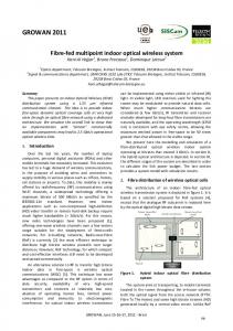
ming option is feasible with VLC systems as long as the minimum SNR for the target bit error rate (BER) is obtained. A possible scenario of future wireless communication on airplanes is depicted in Fig. 2. Service is established through a combination of wired, wireless, and satellite technologies. Wired base stations (BSs) are merged with WLED-based illumination equipment (reading lamps) to provide passengers with Internet access and a range of multimedia services. Power over Ethernet (PoE) technology is used to transport data traffic and supply the BSs as well as the reading lamps with the required power.
Local data and multimedia server
PoE
BS
BS
PoE
Satellite communication server/system
Reading lamp Portable device with visible light-port
Satellite
Figure 2. Future broadband wireless networking scenario.
TYPICAL INDOOR OW SYSTEM A block diagram of a typical indoor OW system is illustrated in Fig. 3 . A basic OW system consists of a light source, free space as the propagation medium, and a light detector. Information, in the form of digital or analog signals, is input to electronic circuitry that modulates the light source. The source output passes through an optical system (to control the emitted radiation, e.g., to ensure that the transmitter is eye safe) into the free space. The received signal comes through an optical system (e.g., an optical filter that rejects optical noise, a lens system or concentrator that focuses light on the detector), passes along the detector, and the resulting photocurrent is amplified before the signal processing electronics. For most indoor applications, LEDs are the favored light sources due to the relaxed safety regulations, low cost, and high reliability compared to LDs. PIN PDs are commonly used due to their lower cost, tolerance to wide temperature fluctuations, and operation with an inexpensive low-bias voltage compared to avalanche photodiodes (APDs). Simple and low-cost optical carrier modulation and demodulation are usually achieved through intensity modulation with direct detection (IM/DD). The desired waveform is modulated onto the instantaneous power of the optical carrier, and the detector generates a current proportional to the received instantaneous power; that is, only the intensity of the optical wave is detected, and there is no frequency or phase information.
MODULATION TECHNIQUES SINGLE-CARRIER PULSED MODULATION
Input electrical signal
Output electrical signal
Modulator
Amplifier
Light source
Light detector
Optical system
Optical system
Output optical signal
Input optical signal
Free space
Figure 3. Block diagram of a typical indoor OW system.
58
High average power efficiency can be achieved by employing single-carrier (SC) pulsed modulation techniques in which the time-dependent characteristics of the optical pulse is used to convey information. Among several techniques, two schemes are widely used, on-off keying (OOK) and pulse-position modulation (PPM) (Fig. 4). OOK is one of the oldest formats and is the simplest in terms of hardware implementation and integration. It also exhibits a good compromise between complexity and performance. In PPM, an optical pulse is transmitted in one out of S slots per symbol time. The occupied slot position denotes the bit combination conveyed by the symbol. PPM expands the signal bandwidth compared to OOK, but provides higher power efficiency. Besides, the use of PPM imposes more system complexity than OOK since both slot- and symbol-level synchronizations, critical to system performance, are required at the receiver. For detailed explanation and evaluation of these and other SC pulsed modulation techniques techniques, the reader is referred to [1].
MULTIPLE-SUBCARRIER MODULATION MSM techniques for OW links is proposed in [6]. OFDM is a practical realization of multiplesubcarrier modulation (MSM). OFDM is a parallel data transmission scheme in which high
IEEE Communications Magazine • September 2011
ELGALA LAYOUT
8/22/11
2:39 PM
Page 59
data rates can be achieved by transmitting orthogonal subcarriers. OFDM systems do not require complex channel equalizers, the timevarying channel can easily be estimated using frequency-domain channel estimation, and adaptive modulation can be applied based on the uplink/downlink (UL/DL) requested data rates and quality of service (QoS). Also, the possibility to combine OFDM with any multiple access scheme makes it an excellent preference for indoor OW applications. In general, the output of the OFDM modulator is complex. In IM optical systems, quadrature modulation is not possible (i.e., phase information detection is not possible for IM/DD systems). Therefore, the OFDM commonly used in RF communications must be modified. As shown in Fig. 5, two schemes are used to realize OFDM IM/DD optical systems, namely DC biased optical OFDM (DCO-OFDM) [7] and asymmetrically clipped optical OFDM (ACOOFDM) [8]. Both systems are very similar to RF systems designed for wired or wireless communications, but they have their own requirements and methods. A real OFDM signal can be generated by constraining the input to the inverse fast Fourier transform (IFFT) operation to have Hermitian symmetry (Fig. 5). If an ACO-OFDM system only modulates odd frequency subcarriers, then the even frequency subcarriers are set to zero. The DCO-OFDM has (N/2) – 1 independent complex inputs. In both schemes, the DC and the –N/2 subcarriers are set to zero to ensure that the output only consists of real values. In ACO-OFDM, the generated bipolar signal is converted to unipolar through clipping of all negative values at zero. In contrast to ACOOFDM, the generated bipolar time domain signal in DCO-OFDM is used to modulate the optical carrier intensity after setting a proper DC operating point.
MAC LAYER IMPLEMENTATION The MAC protocol provides user addressing and channel access control mechanisms for several terminals to communicate within a network. A simulator was designed by V. Chengottarasappan et al. in 2004 to simulate several RF MAC protocols in an OW environment. The performance of one of these protocols, multiple access collision avoidance (MACA), is reported. The efficiency reaches a maximum of 22–25 percent. The reported low throughput is attributed to the design of this specific protocol, where only two nodes can transmit data at a time. Possible extension to the MACA protocol includes subcarrier multiplexing or wavelength-based multiple access. The researchers at the Nakagawa laboratories in Japan have implemented a full-duplex VLC system based on carrier sense multiple access with collision detection (CSMA/CD). The choice of the CSMA/CD method targets compatibility with wireline LAN communications such as Ethernet networks and PLC. Infrared radiation of 850 nm wavelength is used as a medium for the uplink in a point-to-multipoint bidirectional scenario. The European Community Home Gigabit
IEEE Communications Magazine • September 2011
Intensity
0
1
OOK
0
Intensity 11
0
1
1
0
1
0
1
0
0
Time PPM
00
Symbol
10
Time
Figure 4. Demonstrating SC pulsed modulation schemes, OOK and PPM.
Access project (OMEGA) considers IR and visible light communications to provide wireless connectivity. PLC is used to provide a backbone within the home. A technology-independent MAC layer will control this network and provide services as well as connectivity to any number of access points in any room. Furthermore, this MAC layer will allow the service to follow the user from one access point to another. For an OW LAN based on an LOS path, blockage sensing (shadowing due to the random movement of people in a room) can improve the performance of MAC protocols. A modified polling protocol with blockage sensing is proposed by Hou et al. in 2003 that assigns channels according to the available channel state information. Therefore, blockage occurrence during a user transmission is avoided and the channel is immediately reassigned to enhance system efficiency and user’s QoS. Simulation results show significant improvements in both system throughput and average transfer delay compared to classical time-division multiple access (TDMA) and polling type MAC protocols.
MULTIPLE ACCESS TECHNIQUES AND OPTICAL MIMO MULTIPLE ACCESS TECHNIQUES Multiple access techniques are performed in the physical layer to allow several users to get access simultaneously to the available network services. Single cell topology using a single optical access point (OAP) per-user or per-room and a cellular topology with spatial reuse using multiple OAPs are three probable topologies for indoor coverage as shown in Fig. 6. A suitable topology is chosen based on the room size, number of users, users’ mobility, and/or the offered network services. In a single cell topology per user, each user has a dedicated AP and all resources are available, so multiple access techniques are not required. This topology is practical, for example, when the existing reading lamps on top of each seat in airplanes, trains, and buses are used in
59
ELGALA LAYOUT
8/22/11
2:39 PM
Conventional encoder
Modulation
Viterbi decoder
Maximum permissible AC/pulsed current Maximum permissible DC current DC operating point Turn-on voltage Output amplitude
Interleaver
Page 60
DCO-OFDM
Deinterleaver
Demapping Channel estimation symbol equalization
ACO-OFDM
Mapping
Demodulation Input amplitude
IFFT operation
FFT operation Indok -N/2
CP addition
-5 -4 -3 -2 -1 DC 1 2 3 4 5
(N/2)-1
Clipping D/A
CP removal
Synchronize Indok -N/2
-5 -4 -3 -2 -1 DC 1 2 3 4 5 Complex conjugate Optical Tx
(N/2)-1
A/D
Data symbols Optical channel
Optical Rx
Figure 5. DCO-OFDM and ACO-OFDM building blocks and LED input-output/voltage-current relationship. VLC as OAPs. A single cell per room topology can be utilized in moderate size rooms or offices, whereas a cellular topology is required, for example, to provide coverage in a big conference hall. Electrical multiplexing and optical multiplexing are two possible strategies to realize multiple access in a single cell per room or cellular topology. Electrical multiplexing techniques include TDMA, frequency-division multiple access (FDMA), or code-division multiple access (CDMA). Optical multiplexing techniques include wavelength-division multiple access (WDMA) and space-division multiple access (SDMA). Electrical Multiplexing Techniques •TDMA is a synchronous technique where users cannot communicate independently and simultaneously. Nonoverlapping time slots are allocated to different users based on the requested data rates and QoS. TDMA provides high power efficiency, which is the most important metric for OW systems, while reducing the transmission capacity per user [1]. •FDMA transmission allows multiple users to transmit simultaneously using different frequencies within a single cell per room topology. In a cellular system, the bandwidth is divided into nonoverlapping frequency bands, and each OAP is allocated a different band. In orthogonal frequency-division multiple access (OFDMA), users are allocated time/frequency slots (chunks) span-
60
ning several OFDM symbols and subcarriers. In general, power efficiency is the main drawback of FDMA and worsens as the number of subcarriers increases. •For optical CDMA systems, the commonly used techniques rely on direct sequence spreading where users can access the same channel using optical orthogonal codes (OOCs). This means flexibility of adding users and asynchronous access capability. Users are able to transmit at overlapping times and wavelengths; therefore, it is also possible to implement hybrid optical systems such as WDMA/CDMA or TDMA/CDMA. Optical Multiplexing Techniques •In WDMA, for example, a number of users transmit simultaneously using different wavelengths. Each user has an independent wavelength together with an optical tunable reception filter. In general, such a complex structure is expensive and not desirable. •The short wavelength of the optical signal makes it possible to achieve high angular resolution; therefore, SDMA uses ADRs to discriminate signals and reduce co-channel interference (CCI) between channels in the same cell [2]. The potential disadvantage of this technique is increased complexity.
OPTICAL MIMO Multiple-input multiple-output (MIMO) techniques are promising candidates to achieve high data rate indoor OW systems.
IEEE Communications Magazine • September 2011
ELGALA LAYOUT
8/22/11
2:39 PM
Page 61
MIMO Using Parallel SISO Links — One way to implement an indoor MIMO system for OWC is by realizing parallel single-input single-output (SISO) links. Such parallel communication involves simultaneous sending of different data streams using a transmitter array where each detector in the receiver array is illuminated by a single source. This requires accurate alignment of transmitter and receiver. In addition, eliminating signal interference must be considered through appropriate settings of the array structures, the source beamwidth, and the detector FOV. MIMO Using Spatial Multiplexing — Another implementation of optical MIMO systems is combining MIMO with OFDM. A spatial multiplexing indoor MIMO technique for VLC technology using OFDM was considered in [9]. It is shown that the channel is highly correlated, which limits system performance at different locations inside the room. The performance can be enhanced remarkably by considering an imaging diversity receivers technique to decorrelate the MIMO channel matrix. This is achieved at the expense of placing a lens at the proper location between the transmitters and the receivers for LOS paths. Imaging receivers cannot collect light over an FOV as wide as a nonimaging angle-diversity receiver, since the elements of the latter can be oriented in any direction. Also, the size of the imaging lens and detector array depend on the location; therefore, imaging receivers are not suitable for all applications. MIMO Using Spatial Modulation — An alternative MIMO system that reduces the alignment requirement can be implemented by adopting the spatial modulation (SM) technique, which is proposed recently by Mesleh et al. in 2010 [10]. In optical-SM, multiple transmitters exist where only a single transmitter is activated at any given particular time instant. The active transmitter transmits a pulse with certain optical power. The index of the active transmitter is estimated at the receiver and used to encode the information bits.
OPEN ISSUES AND CONTINUING RESEARCH UPLINK CHANNEL Unlike broadcasting applications, serving users’ requests and performing adaptive modulation relying on channel information require a realization of an uplink channel which is a challenging design task. A proposal is foreseen through wavelength-division duplexing (WDD) using different IR wavelengths. However, this approach may require alignment or tracking. Light reflected by a corner cube reflector to realize the uplink channel is proposed by Komine et al. in 2003 as a possible solution to avoid these requirements. The achieved uplink data rate and the reflector placement need further investigation. It is also possible to use the time-division duplexing (TDD) technique to separate the downlink and the uplink signals. Specifically for VLC, the off-periods of the pulse width modulation (PWM) dimming waveform is considered by Kavehrad in 2007 to realize the uplink transmis-
IEEE Communications Magazine • September 2011
U = User = Cell Handover U1
U2
U3
U4
U1
U4
U2
U3
U1 U4
U3 U6
U2 U5
U6 (a)
U7 U5
(b)
U8 (c)
Figure 6. Different topologies for indoor coverage: a) single OAP per-user; b) single OAP per-room; and c) cellular topology with spatial reuse using multiple OAPs.
sion. PWM controls the pulse width and duty cycle of the LED driving current causing the LED light to vary its intensity. The use of RF to provide the uplink is even considered by Hou and O’Brien in 2006. Further study is required to compare alternatives and evaluate the performance.
LED MODULATION BANDWIDTH For VLC systems, the performance is limited by the modulation bandwidth of the blue-chip LEDs. Mitigating the poor performance of such LEDs is the most important step towards achieving high-speed data transmission. It is shown by Grubor et al. in 2007 that the long response time of the phosphor limits the available modulation bandwidth to several megahertz. By using a simple color filter to detect only the blue peak of the emission spectrum, the resulting modulation bandwidth is approximately an order of magnitude larger. The maximum reported bandwidth achieved through this approach is around 20 MHz. A transmitter equalization approach is an alternative solution proposed by Le-Minh et al. in 2008 where the frequency response of each LED in an array is set with a simple resonant circuit (i.e., each LED has a different frequency response). Careful selection of the different responses allows a high net bandwidth. An experimental demonstration using 16 LEDs (2.5 MHz unequalized bandwidth) achieves 25 MHz net bandwidth. Multiple resonant equalization of a single LED is presented again by Le-Minh et al. in 2008 and a 45 MHz net bandwidth was reported. Combining the blue filtering approach with this approach achieves a data rate of 80 Mb/s. Instead, a receiver equalization approach is proposed by Zeng et al. in 2008 to compensate for the slow decay of the phosphor. This is achieved by estimating the cut-off frequency of the LED from the decay time of the impulse response and using a first order equalizer for compensation.
LED NONLINEARITY In optical systems, the LED is a major source of nonlinearity. This nonlinear behavior is particularly important when analog OFDM modulating
61
ELGALA LAYOUT
8/22/11
2:39 PM
Selecting an LED with high AC/pulsed current level, i.e. large dynamic range, enhances the performance. Moreover, error-performance is improved by considering an LED with low voltage-current slope characteristics.
Page 62
signal is used. For example, the LED nonlinear behavior degrades the bipolar time domain DCO-OFDM signal through amplitude distortion, clipping of the lower peaks, and clipping of the upper peaks (Fig. 5). The lower peaks are clipped at the turn-on voltage (TOV) of the LED, and the upper peaks are clipped at the saturation voltage, which corresponds to the maximum permissible AC/pulsed saturation current of the LED recommended by the manufacturer. The clipping of the upper peaks ensures that the LED chip does not overheat, in order to avoid degradation in output light or, in the worst case, total failure. In order to control the LED nonlinearity induced distortion, searching for an optimum DC operating point and optimal OFDM signal power to modulate the LED intensity is required, i.e. to operate the LED in a quasi-linear segment of its characteristic around the chosen DC operating point. Selecting an LED with high AC/pulsed current level (i.e., large dynamic range) enhances the performance. Moreover, error-performance is improved by considering an LED with low voltage-current slope characteristics. Additionally, a predistorter that uses the LED inverse characteristics as nonlinear distortion compensator is proposed by Elgala et al. in 2009. Indeed, peak-to-average power ration (PAPR) reduction techniques can also be considered to reduce power backoff levels [11].
COMPATIBILITY WITH ILLUMINATION FUNCTIONS Another challenging difficulty for VLC is compatibility with commonly used PWM dimming. As the channel is not present during the off periods of the PWM waveform, an approach to combining PPM modulation with dimming was proposed by Lopez-Hernandez et al. in 2006 to allow data transmission at 500 kb/s. However, further work is required to modify other SC modulation techniques and to combine the PWM dimming signal with the OFDM signal.
CONCLUSION This article reviews OW communication technology, overviews research activities, and states the design challenges that still need to be overcome before being able to realize an entire OW system that can be commercially deployed. It is anticipated that further experimental and theoretical studies will provide enhanced foundations for important new developments in this very rapidly growing area.
ACKNOWLEDGMENT We acknowledge the support of the German Federal Ministry of Economics and Technology (BMWi) under grant 20K0806G as part of the Lufo 2nd Call project SINTEG.
62
REFERENCES [1] J. M. Kahn and J. R. Barry, “Wireless Infrared Communications,” Proc. IEEE, vol. 85, no. 2, Feb. 1997, pp. 265–98. [2] J. B. Carruther and J. M. Kahn, “Angle Diversity for Nondirected Wireless Infrared Communication,” IEEE Trans. Commun., vol. 48, no. 6, June 2000, pp. 960–69. [3] Y. Tanaka et al., “Indoor Visible Light Data Transmission System Utilizing White LED Lights,” IEICE Trans. Commun., vol. E86-B, no. 8, Aug. 2003, pp. 2440–54. [4] J. Vucic et al., “513 Mbit/s Visible Light Communications Link Based on DMT-Modulation of a White LED,” J. Lightwave Tech., vol. 28, no. 24, Dec. 2010, pp. 3512–18. [5] J. Grubor et al., “Bandwidth Efficient Indoor Optical Wireless Communications with White Light Emitting Diodes,” Proc. 6th Int’l. Symp. Commun. Sys., Networks and Digital Signal Proc., vol. 1, Graz, Austria, 23–25 June 2008, pp. 165–69. [6] T. Ohtsuki, “Multiple–Subcarrier Modulation in Optical Wireless Communications,” IEEE Commun. Mag., vol. 41, no. 3, Mar. 2003, pp. 74–79. [7] H. Elgala, R. Mesleh, and H. Haas, “Indoor Broadcasting via White LEDs and OFDM,” IEEE Trans. Consumer Electronics, vol. 55, no. 3, Aug. 2009, pp. 1127–1134. [8] J. Armstrong and A. Lowery, “Power Efficient Optical OFDM,” Electronics Lett., vol. 42, no. 6, 16 Mar. 2006, pp. 370–72. [9] L. Zeng et al., “High Data Rate Multiple Input Multiple Output (MIMO) Optical Wireless Communications Using White LED Lighting,” IEEE JSAC, vol. 27, no. 9, Dec. 2009, pp. 1654–62. [10] R. Mesleh et al., “Indoor MIMO Optical Wireless Communication Using Spatial Modulation,” IEEE ICC ’10, Cape Town, South Africa, 22–27 May 2010, pp. 1–5. [11] W. Kang and S. Hranilovic, “Power Reduction Techniques for Multiplesubcarrier Modulated Diffuse Wireless Optical Channels,” IEEE Trans. Commun., vol. 56, no. 2, Feb. 2008, pp. 279–88.
BIOGRAPHIES H ANY E LGALA [S’02, M’10] received a Ph.D. degree from Jacobs University, Bremen, Germany, in 2010. He received a B.Sc. degree in electronics and communications from Ain-Shams University in 2000 and completed his M.Sc. degree in microsystems engineering from Furtwangen University in 2003. He is currently a postdoctoral fellow in the Department of Electrical Engineering and Computer Science at Jacobs University. Since 2005 he has been conducting research on indoor optical wireless communication. His main research interests are in the areas of communication systems, digital signal processing, and circuit design. RAED MESLEH [S’00, M’08] received a B.Sc. degree in communication engineering from Yarmouk University, Irbid, Jordan, in 2000, an M.Sc. degree in communication technology from Ulm University, Germany, in 2004, and a Ph.D. degree in electrical engineering from Jacobs University in 2007. Since September 2010 he has been with the Electrical Engineering Department, University of Tabuk, Saudi Arabia, and the Sensor Network and Cellular System (SNCS) research center. His main research interests are in the areas of MIMO and optical wireless communication. H ARALD H AAS [S’98-A’00-M’03] received a Ph.D. degree from the University of Edinburgh, Scotland, in 2001. His main research interests are in the areas of wireless system engineering and digital signal processing, with a particular focus on interference-aware MAC protocols, multiuser access, link adaptation, scheduling, dynamic resource allocation, multiple antenna systems, and optical wireless communication. He joined Jacobs University in September 2002 where he has since been a professor of electrical engineering. In June 2007 he joined the University of Edinburgh where he holds the Chair of Mobile Communications in the Institute for Digital Communications.
IEEE Communications Magazine • September 2011