Feb 13, 2014 - for Experimental Mechanics Inc., The Fairmont Press. Ludwig, O., Drezet, J.-M., Commet, B., Heinrich, B., 2006. Modelling of internal stresses in ...
Journal of Materials Processing Technology 214 (2014) 1372–1378
Contents lists available at ScienceDirect
Journal of Materials Processing Technology journal homepage: www.elsevier.com/locate/jmatprotec
Influence of a wiper on residual stresses in AA7050 rolling plate ingots J.-M. Drezet a,∗ , Th. Pirling b a b
LSMX, Ecole Polytechnique Fédérale de Lausanne, Station 12, CH-1015 Lausanne, Switzerland Institut Laue Langevin, ILL-Grenoble, F-38042 Grenoble, France
a r t i c l e
i n f o
Article history: Received 9 November 2013 Received in revised form 4 February 2014 Accepted 5 February 2014 Available online 13 February 2014 Keywords: Aluminum direct chill casting Rolling sheet ingots Residual stresses Neutron diffraction Thermomechanical modeling Elastic energy
a b s t r a c t As-cast stresses in the foot of the ingot corresponding to the transient start-up phase of the direct chill casting have been determined in aluminum alloy AA7050 rectangular ingots. This high strength alloy is usually cast with a wiper that is placed below the mold and ejects the falling water from its surface thus reducing the cooling intensity. The ingot being hotter, internal stresses are relaxed. The efficiency of a wiper has been evaluated using both neutron diffraction measurements on ingots cast with and without a wiper and a 3D numerical model simulating the stress generation during casting. The stress level is reduced by 33% when a wiper is used during casting and the stored elastic energy by 50%. © 2014 Elsevier B.V. All rights reserved.
1. Introduction In the fabrication of aluminum rolling plates, the first step is the semi-continuous casting of a rectangular ingot. The most commonly used process is known as direct chill (DC) casting (Drezet, 1996). This process gives rise to large thermally induced strains that lead to several types of casting defects (distortions, cold cracks, porosity, solidification cracking, etc.). During casting, thermally induced stresses are partially relieved by permanent deformation. When these residual stresses overcome the deformation limit of the alloy, cracks are generated either during solidification (hot tears) or during cooling (cold cracks). The formation of these cracks usually results in rejection of the cast part. Furthermore, thermally induced deformations can cause downstream processing issues during the sawing stage prior to rolling. For large ingot formats and high strength alloys, sawing becomes a delicate task owing to the risk of saw pinching or crack initiation ahead of the saw. To overcome these limitations, wipers are placed below the open mold during casting in order to eject the falling water from the ingot surface. Cooling intensity and thus internal stresses are significantly reduced and stress relief treatment right after casting can be suppressed. The computation of stresses during DC casting of aluminum alloys has been the scope of several studies since the late 90s
∗ Corresponding author. Tel.: +41 21 693 39 20; fax: +41 21 693 58 90. E-mail address: jean-marie.drezet@epfl.ch (J.-M. Drezet). http://dx.doi.org/10.1016/j.jmatprotec.2014.02.011 0924-0136/© 2014 Elsevier B.V. All rights reserved.
(Drezet and Rappaz, 1996; Hannart et al., 1994; Fjaer and Mo, 1990; Sengupta et al., 2005; Boender et al., 2004; Ludwig et al., 2006; Droste et al., 2000; Droste et al., 2002; Phillion et al., 2006) and is a well established technique nowadays. Many numerical models have allowed researchers to compute the ingot distortions and the associated residual stresses. The validation of these models was often done by comparing the computed and measured ingot distortions, e.g. the butt-curl (Droste et al., 2000) and the rolling face pull-in for rolling sheet ingots produced by DC (Droste et al., 2002) or electromagnetic casting (Evans, 1995). Validation against the computed room-temperature residual stresses is limited simply owing to the difficulty of measuring the internal strains and the high variability in the measurements. While some measurements are available for quenching (Escobar et al., 2002) or welding (Ganguly et al., 2005), they remain rare, uncertain and usually are limited to one or two components of the stress tensor, and to the skin of round billets for as-cast materials (Moriceau, 1975; Levy et al., 1974). In contrast to destructive methods for measuring residual stresses (hole-drilling strain gage, cut compliance, layer removal technique), physical methods such as neutron, Xray or ultra-sound diffraction are very attractive (Lu, 1996) since they can yield all stress components. In addition, the use of physical methods allows for measurements deep within a sample up to the energy limit of the beam. With the development of powerful neutron beams, it is now possible to measure the residual strains rather deep in light metal alloys such as aluminum and magnesium since these metals are relatively transparent to neutrons (Hao et al., 2005; Drezet and Phillion, 2010), as opposed to copper and
J.-M. Drezet, Th. Pirling / Journal of Materials Processing Technology 214 (2014) 1372–1378
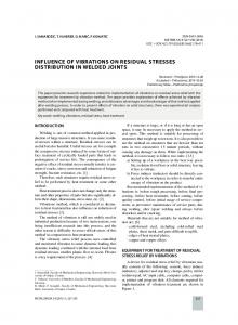
iron. Such measurements allow for sophisticated model validation. This has been done for AA6063 extrusion billets cast at different speeds and measured at two different diffractometers. Using a FE model to compute the stress build-up during casting (Drezet and Phillion, 2010) together with the thermal and mechanical properties, the sawing itself was modeled by the removal of elements, similarly to the strategy adopted by Drezet et al. (2007) to study possible crack initiation and propagation. It was shown, for residual stress measurements, the minimum billet section-length must be greater than at least three times the billet radius to ensure that the residual stresses at its mid-height are not relaxed during sawing. The validation of the FE casting model against residual stresses in AA6063 round billets is fully detailed in Drezet and Phillion (2010), Drezet et al. (2012a). The aim of the present work is to extend this validation to the case of rolling plate ingots in order to assess the benefits of using a wiper during the start-up phase of casting. Residual strain measurements have been undertaken on two rectangular AA7050 rolling Plates 300 mm in thickness, 600 mm in width and 1 m in length cast at 90 mm/min. One ingot is cast with the use of a wiper, the second without it. The residual stress measurements have been carried out at the neutron diffractometer SALSA at ILL-Grenoble, France (SALSA, 1998). The goal of the present work is: • to quantify the level of as-cast residual stresses in the foot of the slab, • to apply the finite element (FE) model of DC casting on a new alloy, AA7050, and a new format, rectangular rolling ingots, • and to quantify the reduction of internal stresses and stored elastic energy when using a wiper. Section 2 provides a description of the material and the principles of residual stress measurement using neutron diffraction. The finite element (FE) model of the DC casting process is briefly recalled in Section 3. The measurements are presented in Section 6 and compared with the values predicted by the three dimensional FE casting model. The reduction in stress level and in stored elastic energy is assessed in the last section. 2. Material and neutron diffraction residual stress measurement 2.1. Material and casting procedure The AA7050 alloy is a heat treatable alloy from the 7xxx series alloy containing Zn, Mg, Cu and Zr. Its solidus, rigidity (corresponding to the onset of thermal contraction) and liquidus temperatures were calculated using the software ProPHASE® , based on a model proposed by Sigli et al. (1998). In order to reduce possible cracking during and after casting, high strength aluminum alloys are usually cast with a wiper placed on its surface as schematically shown in Fig. 1. The wiper ejects the running water from the ingot surface and thus reduces the efficiency of cooling. The ingot being hotter, internal stresses are reduced. Two 1 m long rolling plates were cast semi-continuously at Constellium CRV, Voreppe, France. After the transient start-up phase, the casting speed was set to a steady state speed of 90 mm/min. Keeping all casting parameters constant as much as possible, one ingot was cast with a wiper and one was cast without a wiper. Both ingots were wrapped in security nets in case of erratic explosion and transported to Institut Laue Langevin, Grenoble, for neutron diffraction residual stress measurements. The weight of each sample was slightly lower than 500 kg. Typical grain size in this casting was 100 ± 30 m with a globular microstructure due to the use of grain refiner.
1373
Fig. 1. Schematics of the use of a wiper for casting high strength aluminum alloys.
2.2. Neutron diffraction measurements SALSA (SALSA, 1998) is a neutron diffraction instrument designed for strain measurements through the accurate determination of lattice spacing. In a stressed material, the lattice spacing acts as a kind of strain gauge. The elastic strain is given by ε = (d − d0 )/d0 , where d0 and d are, respectively, the stress-free and actual lattice spacing for a given crystal plane family. Using Hooke’s law, the measured strain can be converted to stress with the appropriate elastic constants. Diffraction can be understood in terms of the Bragg’s law � = 2d sin � where d is the lattice spacing, � the wavelength and 2� the diffraction angle. Therefore in order to measure the lattice spacing for determining strains and stresses, either the wavelength is fixed and the diffraction angle is measured (monochromatic angular dispersive) or the diffraction angle is fixed and the wavelength determined (polychromatic time-of-flight). In the case of monochromatic neutron source where only one diffraction peak is recorded, for fcc metals such as aluminum, the (3 1 1) diffracting planes are commonly used to measure the strain since they do not accumulate significant intergranular stresses and hence exhibit similar behavior as that of the bulk. The (3 1 1) is also recommended for use in the measurement of residual strains by neutrons in aluminum alloys by the ISO VAMAS standard (Webster, 2001). A series of stress free reference samples, for measurement of the reference lattice constant d0 , were also acquired. These samples were electro-discharge machined along the casting direction at the symmetry plane of the slab every 20 mm in order to account for any variation in d0 that may be present due to long range chemical inhomogeneities, i.e. macrosegregation. Located at ILL-Grenoble, SALSA uses a large crystal monochromator to select a particular neutron wavelength. The material to be studied is placed in this monochromatic neutron beam, and the scattered neutrons are collected on a large 2D detector to determine accurately the lattice ˚ and the position of spacing. The wavelength is constant (1.66 A) the diffraction peak is recorded on a position sensitive detector. For the measurements at SALSA, 2 mm radial focusing collimators were used to reduce experimental errors introduced by the optics. The instrumental gauge volume was set to 2 mm × 2 mm × 4 mm as strains may vary in all directions during the transient start up phase. 2.3. Residual stress state in as-cast sheet ingots In DC cast extrusion billets (Drezet et al., 2012a), the elastic stress and strain tensors have only four components due to the axisymmetric billet geometry and casting conditions. For rolling slabs, this is no longer the case and the stress/strain tensor has 6 components. The strain measurements were carried out in the orthogonal (x, y, z) reference frame (axis z is along casting direction and gravity, axis x is along the width of the ingot and axis y along
1374
J.-M. Drezet, Th. Pirling / Journal of Materials Processing Technology 214 (2014) 1372–1378
Fig. 2. Reference frame (xyz) and the 4 scan lines, OA, DE, BC and DF along which xx, yy and zz strain components have been measured. Point O is the center lower point of the slab. One quarter of the ingot is represented owing to the two symmetry planes.
its thickness) along four scan lines, OA, DE, EF and BC. The location of these scan lines are depicted in Fig. 2 where only one quarter of the slab is represented owing to the presence of the two symmetry planes. Applying Hooke’s law with a Young’s modulus E (71.3 GPa) and Poisson’s ratio � (0.3), the stress component along each axis writes: �xx = 2�εxx + �(εxx + εyy + εzz ) �yy = 2�εyy + �(εxx + εyy + εzz )
(1)
�zz = 2�εzz + �(εxx + εyy + εzz ) where � and � are the Lamé coefficients: �=
�E (1 + �)(1 − 2�)
and � =
E 2(1 + �)
(2)
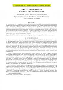
For each of the three measured strain components, both the beam orientation and the position of the ingot within the neutron chamber must be varied. The length of the beam path varies from almost zero at the ingot surface to values of the order of the ingot width, i.e. 300 mm. In that case, time measurements are greatly longer. Fig. 3 shows a picture of the ingot in place in the neutron chamber for measuring different strain components. 3. Thermomechanical model of casting The DC casting process of rectangular rolling sheet ingot was simulated using a transient three dimensional coupled thermal mechanical model implemented in the commercial finite element code ABAQUS® 6.10. Due to symmetry, the computational domain includes one quarter of the rolling plate ingot. The mesh consists of 50 layers of elements, with each 20 mm-high layer containing 75 elements, for a total cast length of 1000 mm. The coordinate system was fixed with respect to the slab and the incoming flow of liquid metal was modeled through the activation of successive layers at a rate that corresponds to the experimental casting speed of 90 mm/min. The total simulation time was 650 s for the casting per se plus a 2 h cool-down period. A CPU time around 10 h was required to run the computation. The initial condition was a pouring temperature of 670 ◦ C. The horizontal boundary conditions were also moved up along the domain at a rate of 90 mm/min. These boundary conditions account for primary cooling through the mold, air gap formation and secondary cooling at the point where the water hits the ingot and flows along its surface (Drezet et al.,
2000). To simulate the presence of a wiper, an adiabatic condition was used at a height corresponding to the position of the liquidus line at the symmetry axis. The heat transfer to the dummy block was simplified and modeled using a mean heat transfer coefficient of 200 W/m2 K. The mechanical properties of the AA7050 alloy were taken from the work of Lalpoor et al. (2009, 2010). At temperatures higher than 200 ◦ C, visco-plastic effects are considered with a positive strain rate exponent. Further details on the FE model of casting can be found in Drezet (1996), Drezet and Rappaz (1996), Droste et al. (2002), Drezet et al. (2012a). Fig. 4 shows the computed temperature distribution and extension of the mushy zone (solid volume fractions between 0.0 and 1.0) on the ingot interior and on its skin at the time metal pouring is stopped, i.e. at 650 s. The results are presented for both casting procedures, i.e. in the absence of a wiper and when a wiper is used. At the moment liquid metal pouring is stopped, a large liquid pool is still present within the ingot and will solidify during further cooling. The efficiency of the primary and secondary cooling clearly appears but the secondary cooling is limited to a portion of the ingot surface above the wiper. Most of the ingot remains above 200 ◦ C when a wiper is used. On the other hand, the mushy zone is little affected, which means that the solidification conditions and therefore the as-cast microstructure are similar for both casting procedures.
4. Computed and measured residual stress profiles In this section, measured as-cast residual stress profiles are compared with the computed ones along the four scan lines OA, DE, DF and BC. Fig. 5 shows the xx, yy and zz stress component distribution along the axis OA, i.e. along the axis of symmetry of the ingot (cf. Fig. 2) when casting was performed with and without a wiper. A similar scale is used to better see the differences in terms of stress level. Both distributions exhibit the same trends and are rather well reproduced by the FE model: a bi-axial compression stress state at the very bottom of the ingot and a transition to a tri-axial stress state after a cast length of 100 mm similarly to the situation reported for round billets (Drezet et al., 2012a). As expected, the stress level is much lower when a wiper is used, roughly 50% lower. In the absence of a wiper, the xx stress component goes through a maximum at a cast length of 120 mm before reaching a plateau. This effect is less pronounced with the presence of a wiper. Fig. 6 shows the stress distribution along the axis DE, i.e. along a short side close to the foot of the ingot (cf. Fig. 2) when casting was performed with and without a wiper. The surface is in bi-axial compression stress state whereas the center is in tri-axial tension. Again, stresses are much lower when a wiper is used during casting. The FE model underestimates the xx stress component at the ingot surface. Fig. 7 presents the stress distribution along the axis DF, i.e. along a long side close to the foot of the ingot (cf. Fig. 2) when casting was performed with and without a wiper. It is interesting to notice that the yy and zz stress components both exhibit a maximum when going from tension close at the symmetry axis (x = 0) to compression at the surface. This result gives valuable information to study sub-surface crack initiation in agreement with the work of Boender et al. (2004) who analyzed J cracks that initiate at the ingot surface in the mold and then propagate in zones of high tensile stresses. Fig. 8 shows the stress distribution along the scan line BC located 165 mm above segment DF (cf. Fig. 2) for both casting procedures. ND stress measurements were not carried out for the ingot cast with a wiper. The stress distributions along scan line BC are similar to these found for the scan line DE except a lower compression appears at the ingot surface.
J.-M. Drezet, Th. Pirling / Journal of Materials Processing Technology 214 (2014) 1372–1378
1375
Fig. 3. Ingot positioning for measuring residual stresses at SALSA.
Fig. 4. Influence of using a wiper on temperature distribution and mushy zone extension on the ingot interior and on its skin. Gray regions correspond to the liquid phase. Time corresponds to the moment liquid metal pouring is stopped, 650 s.
200
200
100
100
50 0 0
100
200
300
400
-50
-100 -150
ND-xx
ND-yy
FEM-xx
FEMyy
ND-zz FEMzz
500
Stress (MPa)
150
stress (MPa)
150
50 0 0
50
100
150
200
250
-50 -100 -150
ND-xx
ND-yy
ND-zz
FEM-xx
FEMyy
FEM-zz
-200
-200
z-mm
z-mm
Fig. 5. Computed and measured stress profiles along OA without the use of a wiper during casting (left) and with the use of a wiper (right).
300
1376
150
150
100
100
50
50
Stress (MPa)
stress (MPa)
J.-M. Drezet, Th. Pirling / Journal of Materials Processing Technology 214 (2014) 1372–1378
0 -50
0
20
40
60
80
120
100
140
160
-100 -150
ND-xx
ND-yy
ND-zz
-200
FEM-xx
FEM-yy
FEM-zz
0 50
0
100
150
-50 -100 -150
ND-xx
ND-yy
ND-zz
FEM-xx
FEM-yy
FEM-zz
-200 -250
-250
y-mm
y-mm
150
150
100
100
50
50
0 50
0
100
150
200
250
300
-50
-100 -150
ND-xx
ND-yy
ND-zz
FEM-xx
FEM-yy
FEM-zz
Stress (MPa)
Stress (MPa)
Fig. 6. Computed and measured stress profiles along DE without the use of a wiper during casting (left) and with the use of a wiper (right).
0 -50
0
-100
50
100
150
200
250
FEM-xx
FEM-yy
FEM-zz
ND-xx
ND-yy
ND-zz
300
-150
-200
-200
x-mm
x-mm
Fig. 7. Computed and measured stress profiles along DF without the use of a wiper during casting (left) and with the use of a wiper (right).
5. Stress level and stored elastic energies
of the AA7050 alloy is not nil (Lalpoor et al., 2010) and stresses are relaxed by visco-plastic deformation. Similarly, Fig. 10 shows the computed evolution of the stored elastic energy, during casting per se, i.e. for times lower than 650 s, and further cooling down to room temperature (25 ◦ C) of the ingot on the casting pit. This energy is calculated for the whole computation domain i.e. for one quarter of the full ingot. It increases gradually as the ingot is cast owing to increasing stresses and plastic flow and reaches a maximum at the end of casting, i.e. at 650 s. This maximum is around 2.6 kJ for the ingot cast without a wiper (high stress level) and much lower, 0.7 kJ, for the other ingot (low stress level). In both cases, this energy rapidly decreases for a short period of time right after casting when the liquid pool solidifies. Later on, the elastic energy continues to decrease for the ingot cast without a wiper whereas it increases steadily for the ingot cast with
200
200
150
150
100
100
50 0 -50
0
30
60
90
-100 -150 -200
120
150
Stress (MPa)
stress (MPa)
The overall agreement between FE results and measured values induces confidence in the DC casting numerical model. This allows us to be more quantitative in terms of both stress and stored elastic energy reductions owing to the use of a wiper during casting. Fig. 9 shows the computed distribution of the Von Mises equivalent stress along the symmetry axis (cf. Fig. 2). High values are found at the very surface of the ingot owing to the high cooling through the dummy block. Then values exhibit a minimum before reaching a plateau in the steady state regime of casting, i.e. when heat transfer is now through the lateral surfaces of the slab. The mean reduction of 33% in the stress level is explained by the fact that the ingot remains rather hot during casting with a wiper, typically above 200 ◦ C (cf. Fig. 4). At these temperatures, the strain rate sensitivity
50 0 -50 0
30
60
90
120
150
-100 ND-xx
ND-yy
ND-zz
FEM-xx
FEM-yy
FEM-zz
y-mm
-150 -200
FEM-xx
FEM-yy
FEM-zz
y-mm
Fig. 8. Computed and measured stress profiles along BC without the use of a wiper during casting (left) and with the use of a wiper (right).
J.-M. Drezet, Th. Pirling / Journal of Materials Processing Technology 214 (2014) 1372–1378
- a 50% reduction in stored elastic energy is obtained when a wiper is used during casting.
90 80
Von Mises (MPa)
1377
70
Considering the numerous input parameters entering into the model (alloy properties, cooling conditions, rheology, etc.), the casting model is able to reproduce the measured stresses and can be used to optimize the position of the wiper along the ingot surface and to determine the stress reduction for other formats and alloys.
60 50 40 30
With a wiper
20
No wiper
10
Acknowledgements
0 0
100
200
300
400
500
z-mm
Stored elastic energy (kJ)
Fig. 9. Influence of using a wiper on the Von Mises equivalent stress along the symmetry axis.
3
The authors express their deep acknowledgements to Constellium CRV, Voreppe, for providing the two rolling plate ingots for neutron diffraction measurements and to the international Neutron Source at ILL for the provision of beam time. References
2.5 2
No wiper 1.5
With a wiper
1 0.5 0 0
2000
4000
6000
8000
10000
time (s) Fig. 10. Computed stored elastic energy for the ingots cast with and without a wiper.
a wiper. This difference is explained by a balance during the cooldown period between stress increase owing to differential thermal contraction and stress decrease by thermally activated plastic flow. The rather high stresses stored in the ingot cast without a wiper are relaxed by visco-plastic flow during cooling whereas the low stresses stored in the ingot cast with a wiper increase slightly owing to thermal contraction. When the ingot is at room temperature, i.e. at the end of the cool-down period, the stored elastic energy is lower for the ingot cast with a wiper, 0.96 kJ, compared to the ingot cast with no wiper, 2 kJ. Dividing this energy by the ingot volume yields an elastic energy density of 43.5 kJ/m3 for the ingot cast without a wiper and 21.3 kJ/m3 for the ingot cast with a wiper. This elastic energy is partially dissipated in case of a sudden crack initiation within the ingot, during casting, further cooling, sawing or even simply during storage. As such, it represents a key value in quantifying the risk of ingot explosion during fabrication. Drezet et al. (2012b) have determined a level of stored elastic energy between 12 and 14 kJ/m3 for AA6063 round billets cast at different speeds. Higher values are found in the present study since AA7050 alloys exhibit higher strength. It is interesting to notice that the reduction in stored elastic energy, 50%, is higher than the reduction in stress level, 33%. 6. Conclusion As-cast residual stresses have been measured on two AA7050 rolling plate ingots cast with and without a wiper using neutron diffraction and compared with the results of a thermomechanical FE model of DC casting: - ingots exhibit tri-axial tension at their interior and bi-axial compression at their surfaces similarly to round billets, - a 33% reduction in internal stress level is determined,
Boender, W., Burghardht, A., van Klaveren, E.P., Rabenberg, J., 2004. Numerical simulation of DC casting, interpreting the results of a thermo-mechanical model. In: Tabereaux, A.T. (Ed.), Light Metals. TMS, Charlotte, USA, pp. 679–684. Drezet, J.-M., (PhD work no. 1509) July 1996. Direct Chill and Electromagnetic Casting of Aluminium Alloys: Thermomechanical Effects and Solidification Aspects. EPFLausanne http://library.epfl.ch/en/theses/ Drezet, J.-M., Phillion, A., 2010. As-cast residual stresses in an aluminum alloy AA6063 billet: neutron diffraction measurements and finite element modeling. Met. Mater. Trans. 41A (December), 3396–3404. Drezet, J.-M., Rappaz, M., 1996. Modelling of ingot distortions during direct chill casting of aluminium alloys. Met. Mater. Trans. A 27A, 3214–3225. Drezet, J.M., Rappaz, M., Grun, G.U., Gremaud, M., 2000. Determination of thermophysical properties and boundary conditions of DC cast aluminium alloys using inverse methods. Met. Trans. A 31, 1627–1634. Drezet, J.-M., Ludwig, O., Jaquerod, C., Waz, E., 2007. Fracture prediction during sawing of DC cast high strength aluminium alloy rolling slabs. International Journal of Cast Metals 20 (3), 163–170. Drezet, J.-M., Pirling, Th., Jacquerod, C., 2012a. Residual stresses in as-cast billets: neutron diffraction measurement and thermomechanical modeling. In: Carlos, E., Suarez (Eds.), Light Metals. TMS, Orlando, USA, pp. 1117–1122. Drezet, J.-M., Evans, A., Pirling, T., Pitié, B., 2012b. Stored elastic energy in aluminium alloy AA6063 billets: residual stress measurements and thermomechanical modelling. Int. J. Cast Met. 25 (March (2)), 110–116. Droste, W., Drezet, J.-M., Gruen, G.-U., Schneider, W., 2000. 3D modeling of ingot geometry development of DC-cast aluminium ingots during the start-up phase. In: Ehrke, K., Schneider, W. (Eds.), Continuous Casting. DGM, Wiley-VCH, Frankfurt, pp. 175–183. Droste, W., Grün, G.-U., Schneider, W., Drezet, J.-M., 2002. Thermo-mechanical modeling to predict shrinkage, shape and mold openings for DC-cast rolling ingots. In: Schneider, W. (Ed.), Light Metals. TMS, Seattle, pp. 703–708. Escobar, K., et al., 2002. On the residual stress control in aluminium alloys 7050. Mater. Sci. Forum. 396–402, 1235–1240. Evans, J.W., 1995. The use of electromagnetic casting for Al, alloys and other metals. JOM Journal of the Minerals, Metals and Materials Society 47 (5), 38–41. Fjaer, H., Mo, A., 1990. Alsp a mathematical model for thermal stresses in direct chill casting of aluminium billets. Met. Trans. Mater. A 21B, 1049–1061. Ganguly, S., Fitzpatrick, M.E., Edwards, L., 2005. Comparative neutron and synchrotron X-ray diffraction studies to determine residuals stress on an as-welded AA2024 plate. Mater. Sci. Forum 790–491, 223–228. Hannart, B., Cialti, F., Schalkwijk, R.V., 1994. Thermal stresses in DC casting of aluminum slabs: application of a finite element model. In: Tabereaux, A.T. (Ed.), Light Metals. TMS, San Fransisco, USA, pp. 879–887. Hao, H., Maijer, D.M., Wells, M.A., Cockcroft, S.L., Rogge, R.B., 2005. Prediction and measurement of residual stresses/strains in a direct chill casting magnesium alloy billet. In: Magnesium Technology, pp. 223–228. Lalpoor, M., Eskin, D.G., Katgerman, L., 2009. Cold cracking assessment in AA7050 billets during direct chill casting ba thermomechanical simulation of residual thermal stresses and application of fracture mechanics. Met. Trans. A 40, 3304–3313. Lalpoor, M., Eskin, D.G., Katgerman, L., 2010. Cold cracking development in AA7050 direct chill cast billets under various conditions. Met. Trans. A 41, 2425–2434. Levy, S.A., et al., 1974. Residual stress measurements for studying ingot cracking. In: Light Metals. TMS, New Orleans, USA, pp. 571–585. Lu, J., 1996. In: Lu, J. (Ed.), Handbook of Measurement of Residual Stresses. Society for Experimental Mechanics Inc., The Fairmont Press. Ludwig, O., Drezet, J.-M., Commet, B., Heinrich, B., 2006. Modelling of internal stresses in DC casting and sawing of high strength aluminum alloys slabs. In: Gandin, C.-A., Bellet, M. (Eds.), Modeling of Casting Welding and Advanced Solidification Processes. Nice, France, pp. 185–192. Moriceau, J., 1975. Thermal stresses in continuous DC casting of Al alloys discussion of hot tearing mechanisms. In: Light Metals. TMS, pp. 119–133.
1378
J.-M. Drezet, Th. Pirling / Journal of Materials Processing Technology 214 (2014) 1372–1378
Phillion, A.B., Maijer, D., Cockcroft, S.L., 2006. Coupled thermal-stress model of the start-up phase of the aluminum direct chill casting process: predictions relating to hot tearing. In: Model Casting, Welding & Adv Solidif Proces XI. TMS, Nice, France, pp. 807–814. 1998. Strain imager for engineering applications SALSA. Institut Laue Langevin, Grenoble, France http://www.ill.eu/instruments-support/instruments-groups/ instruments/salsa/ Sengupta, J., Cockcroft, S.L., Maijer, D.M., Larouche, A., 2005. Quantification of temperature, stress, and strain fields during the start up phase of DC casting process
by using a 3D fully coupled thermal and stress model for AA5182 ingots. Mater. Sci. Eng. A 397, 157–177. Sigli, C., Maenner, L., Sztur, C., Shahani, R., 1998. Phase diagram, solidification and heat treatment of aluminium alloys. In: Sato, T., Kumai, S., Kobayashi, T., Murakami, Y. (Eds.), Proc. International Conference on Aluminum Alloys. JILM, pp. 87–98. Webster, G.A., 2001. VAMAS TWA 20 standard, ISO technical report. ISO, Geneva, Switzerland.