Influence of Friction Stir Welding residual stresses on the mechanical behaviour of aluminium stiffened panels Rui Paulo, Pierpaolo Carlone, Robertt Valente, Filipe Teixeira-Dias, Gaetano Palazzo
To cite this version: Rui Paulo, Pierpaolo Carlone, Robertt Valente, Filipe Teixeira-Dias, Gaetano Palazzo. Influence of Friction Stir Welding residual stresses on the mechanical behaviour of aluminium stiffened panels. 2nd ECCOMAS Young Investigators Conference (YIC 2013), Sep 2013, Bordeaux, France.
HAL Id: hal-00855852 https://hal.archives-ouvertes.fr/hal-00855852 Submitted on 30 Aug 2013
HAL is a multi-disciplinary open access archive for the deposit and dissemination of scientific research documents, whether they are published or not. The documents may come from teaching and research institutions in France or abroad, or from public or private research centers.
L’archive ouverte pluridisciplinaire HAL, est destin´ee au d´epˆot et `a la diffusion de documents scientifiques de niveau recherche, publi´es ou non, ´emanant des ´etablissements d’enseignement et de recherche fran¸cais ou ´etrangers, des laboratoires publics ou priv´es.
YIC2013 Second ECCOMAS Young Investigators Conference 2–6 September 2013, Bordeaux, France
Influence of Friction Stir Welding residual stresses on the mechanical behaviour of aluminium stiffened panels R. Paulo a*, P. Carlone b, R. Valente a, F. Teixeira-Dias a, G.S. Palazzo b a
GRIDS Research Group, Center for Mechanical Technology and Automation (TEMA), Department of Mechanical Engineering, University of Aveiro, Portugal b
Department of Industrial Engineering, University of Salerno, Italy
*
Corresponding author:
[email protected]
Abstract. In this work, the longitudinal residual stresses that arise from FSW processes were measured by means of the Contour Method. These residual stresses were then introduced into a numerical simulation model based on the Finite Element Method (FEM), and their effect on the buckling collapse load of aluminium stiffened panels was assessed. The sensitivity of the models to initial geometrical imperfections was also analysed. Keywords: Stiffened panels; Friction stir welding; Residual stresses; Initial geometrical imperfections.
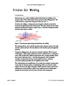
1 INTRODUCTION Stiffened panels are frequently used in engineering applications, when the requirements of strength-to-weight ratio are crucial, as in aeronautical and marine structures. Their design is typically based on the comprehensive strength which is, by itself, highly dependent on the buckling behaviour [1]. The analytical and empirical methods available for the prediction of the stiffened panels' collapse loads have some limitations in their range of application, and not always achieve good accuracy when compared with experimental results [2]. Therefore, numerical analyses based on the FEM can be a good alternative in the study of those structures. Numerical models can also account for some factors related to the welding process, not possible to include with analytical methods. In this field, the influence (on the stiffened panels' strength) of the residual stresses, material properties modifications in the heat affected zone (HAZ) and geometrical distortions have been studied by several authors [1, 3-6]. In this context, remarkable research effort is focused on the application of the FSW process as a suitable alternative to fusion welding processes. FSW is a solid-state welding process, developed and patented by The Welding Institute (TWI) of Cambridge in 1991. Following the early successful applications in aluminium welding, FSW has been applied to other engineering materials such as, for example, copper, steel, titanium and metal matrix composites. During the process, a non-consumable rotating tool, constituted by a shoulder and a pin, is plunged between the adjoining edges of the parts to be welded and moved along the desired weld line. The combined rotation and translation of the tool locally increases the temperature due to heat generated by frictional effects and plastic deformation. The induced softening allows the material being processed to flow around the pin, from the front (leading edge) to the rear (trailing edge) according to complex patterns, resulting in a solid state weld [7]. At the present time, a deeper understanding of static strength as well as of fatigue behaviour of FSW assemblies is highly desired for a wider implementation of the technique in safety-critical components. It is generally accepted that the aforementioned properties mainly depend on the microstructure, the micro-hardness and, to a large extent, on the process induced residual stresses. Even if FSW residual stresses are generally lower with respect to conventional welding processes, an accurate knowledge of their distributions is crucial to numerically investigate buckling behaviour as well as crack growth [8] of welded assemblies. In the present work, the characterisation of FSW residual stresses fields in a section orthogonal to the welding direction was performed by means of the contour method. The collected data was introduced in a stiffened panel finite element model, including a welded zone. The impact of the residual stresses in the collapse load level, when the stiffened panels are subjected to compressive solicitations, was then studied in detail. The sensitivity of the models to distinct geometrical imperfections was also assessed.
2
R. Paulo et al. | Young Investigators Conference 2013
2 CHARACTERISATION OF THE FSW RESIDUAL STRESS FIELDS The Contour Method (CM) is a relaxation method, originally proposed by Prime [9] in 2001, allowing for the evaluation of the residual stress distribution on a specimen section. Theoretically, the method allows for the evaluation of all the three stress components acting on the cut surface. However, evident limitations in the measurement of in-plane displacements reduce the effective applicability of the method to the normal stress component [9]. The application of the conventional contour method is based on four consecutive steps: the cutting of the welded specimen, the shape acquisition on the relaxed surface, the data reduction and the stress computation. In the present investigation, AA2024-T3 aluminium rolled plates were joined by FSW. The process parameters, i.e. tool geometries’ tilt angle and pin penetration, were defined as 2° and 0.2 mm, respectively, according to literature indication and preliminary tests. The used tool consisted of a 20 mm diameter shoulder with a conical pin, characterised by the following dimensions: height of 3.80 mm, larger diameter of 6.20 mm and cone angle of 30°. The residual stress scenario used in the present analysis was obtained assuming an angular velocity of 1400 rpm and a linear velocity of 70 mm/min. As far as the application of the contour method is regarded, an FSW specimen was sectioned in correspondence of the mid-length and orthogonally to the weld line by a WEDM process. Out of plane displacements of the sectioned surfaces have been recorded by means of a Coordinate Measuring Machine (CMM) in a moisture and temperature controlled room. Experimental data was then imported, averaged and fit to a unique smoothing surface in MATLAB. The residual stress distribution was finally inferred by means of an elastic FE model of the cut sample. The measured and digitalised out-of-plane displacements were used, with reversed sign, as input nodal boundary conditions, assuming a block shaped geometry [9]. Additional constraints were imposed on a node on the opposite surface to the displaced one, in order to prevent rigid body motion. The commercial software ANSYS was used to solve the linear elastic boundary value problem. The computed residual stresses, according to the imposed displacements, are shown in Figure 1. In the following section, the procedure developed to investigate the influence of welding stress on the buckling behaviour of stiffened panels is described in detail.
Fig. 1: Plot of the residual stresses as provided by the contour method (dimensions in mm, stresses in MPa).
3 SENSITIVITY OF THE STIFFENED PANELS TO RESIDUAL STRESSES 3.1
Numerical model
The geometry of the stiffened panel adopted in this work, for longitudinal compression load cases, was based on the panel studied by Yoon et al. [6]. A two-stiffener panel was modelled including a welded section between stiffeners. The material of the HAZ was modelled based on a yield stress reduction of 30% when compared to the base material in the surroundings, not affected by thermal effects. The boundary conditions used, when the compressive load was applied are shown in Figure 2. The model uses a mesh of S4R elements in ABAQUS FEM code (shell elements with 4 nodes and reduced integration) with 5 integration points across thickness. 3.2
Methodology
In order to introduce the previously measured residual stresses in the model and assess their influence in the collapse load of the panel, two methodologies were implemented. In the first methodology a two-stage procedure was adopted, based on the literature [4, 10]. In the first stage, the (i) residual stress and (ii) initial geometrical imperfection were applied. A numerical analysis was performed to establish a global equilibrium of the model, using boundary conditions that restrict only rigid body movements. The second stage consisted on the creation of rigid walls on the load edges of the panel and the posterior compression of the panel. Since the first stage of this methodology inevitably induces some distortions on the structure (that can affect the collapse load magnitude), in the second methodology this stage was not considered. Thus, both the residual stresses and the initial geometrical imperfection were applied in a model already including the rigid load walls and, after that, the panel was subjected to compression.
F. Author et al. | Young Investigators Conference 2013
3
For both methodologies, considering the introduction of the experimentally measured residual stresses into the FE model, this stress field was applied in the area indicated in Figure 2. A stress gradient in the 20 elements along the width direction (60 mm), as well as along the 5 integration points in the thickness direction, was considered. Some stress level was added to the rest of the panel aiming for the equilibrium along the longitudinal direction. Finally, analyses with a stress free model were also performed for comparison purposes. In all methodologies the models included initial geometrical imperfections obtained from a preliminary eigenvalue (EV) analysis. The use of these imperfections accounts for similar collapse buckling shapes in the models (with and without initial residual stresses), and therefore enabled the comparison of the collapse loads. The performed analyses included 3 different imperfection shapes, related to the 1 st, 2nd and 3rd eigenvalues (designated by EV1, EV2 and EV3 in what follows), and 2 different maximum magnitudes (0.5 and 1 mm) for each ones of them.
Fig. 2: Description of the model boundary conditions. 3.3
Results
The results for the collapse load, obtained from the FEM analyses, are presented in Table 1, where results for stress-free models and models including residual stresses are listed. Regarding the models including residual stresses, and for both methodologies, it can be seen that the panel collapse load does not show a clear variation trend between the stress free model and the models including residual stresses. However, and for most of the geometrical imperfections, the first method obtained slightly lower collapse loads when compared to the second method. These effects can be somewhat justified by the smaller distortion added to model the equilibrium step in the first method. Table 1: Collapse load results (and respective variation) when compared to the stress free models. Geometrical imp. EV1 mag. = 0.5 mm EV2 mag. = 0.5 mm EV3 mag. = 0.5 mm EV1 mag. = 1 mm EV2 mag. = 1 mm EV3 mag. = 1 mm
Stress free 504.8 504.0 492.0 504.3 501.0 488.2
Method 1 504.64 505.12 490.88 504.16 501.28 487.2
Collapse load (kN) Variation (%) -0.03 0.22 -0.23 -0.03 0.06 -0.20
Method 2 505.6 504.8 492.2 505.0 501.4 488.2
Variation (%) 0.16 0.16 0.03 0.13 0.10 0.00
The variation of strength, exclusively related to the magnitude of the imperfection, is listed in Table 2. The same trend in the results can be observed in all the studied cases (i.e. Stress free, Method 1 and Method 2). The models show some sensitivity to the magnitude when the imperfections EV2 and EV3 were used, while very small variations were observed for imperfection EV1. It is worth mentioning that distinct sensitivity to the magnitude values, depending on the initial imperfection shape, was also previously reported by Paulo et al. [1].
4
R. Paulo et al. | Young Investigators Conference 2013
Table 2: Collapse load variation with the initial imperfection magnitude. Imperfection shape EV1 EV2 EV3
Collapse load variation (%) Comparison between 0.5 and 1 mm magnitudes Stress free Method 1 Method 2 -0.10 -0.10 -0.13 -0.60 -0.76 -0.67 -0.78 -0.75 -0.81
4 CONCLUSIONS In terms of the characterisation of the FSW residual stress fields, the described procedure led to a detailed description of longitudinal residual stresses (orthogonal to the welding direction) in the cross section of the welded plate. Concerning the effect of the residual stresses in the stiffened panel collapse, both the adopted methodologies to include the residual stresses were shown to lead to similar results. As a consequence, the models do not show a clear variation of the collapse load magnitude when residual stresses were considered in the numerical simulation. Also, the structure shows sensitivity to the initial geometrical imperfection shape and magnitude, as expected.
ACKNOWLEDGEMENT The authors wish to acknowledge the support given by Fundação para a Ciência e a Tecnologia, Ministério para a Educação e Ciência, Portugal, under the grants PTDC/EME-PME/113835/2009 and SFRH/BD/82456/2011.
REFERENCES [1] Paulo, R. M. F.; Teixeira-Dias, F.; Valente, R. A. F.; Numerical simulation of aluminium stiffened panels subjected to axial compression: Sensitivity analyses to initial geometrical imperfections and material properties, Thin-Walled Structures 62:65-74, 2013. [2] Paik, J. K.; Veen, S.; Duran, A.; Collette, M.; Ultimate compressive strength design methods of aluminum welded stiffened panel structures for aerospace, marine and land-based applications: A benchmark study, ThinWalled Structures 43:1550-1566, 2005. [3] Khedmati, M. R.; Bayatfar, A.; Rigo, P.; Post-buckling behaviour and strenght of multi-stiffened aluminium panels under combined axial compression and lateral pressure, Thin-Walled Structures 23:39-66, 2010. [4] Murphy, A.; McCune, W.; Quinn, D.; Price, M.; The characterisation of friction stir welding process effects on stiffened panel buckling performance, Thin-Walled Structures 45:339-351, 2007. [5] Rigo, P.; Sarghiuta, R.; Estefen, S.; Lehmann, E.; Otelea, S. C.; Pasqualino, I.; Simonsen, B. C.; Wan, Z.; Yao, T.; Sensitivity analysis on ultimate strength of aluminium stiffened panels, Marine Structures 16:437-468, 2003. [6] Yoon, J. W.; Bray, G. H.; Valente, R. A. F.; Childs, T. E. R.; Buckling analysis for an integrally stiffened panel structure with a friction stir weld, Thin-Walled Structures 47:1608-1622, 2009. [7] Schmidt, H. N. B.; Dickerson, T. L.; Hattel, J. H.; Material flow in butt friction stir welds in AA2024-T3, Acta Materialia 54:1199–1209, 2006. [8] Carlone, P.; Citarella, R.; Lepore, M.; Palazzo, G. S.; Numerical Crack Growth Analysis in AA2024-T3 Friction Stir Welded Butt Joints, Proceedings of the Eighth International Conference on Engineering Computational Technology 2012. [9] Prime, M. B.; Cross-sectional mapping of residual stresses by measuring the surface contour after a cut, Journal of Engineering Materials and Technology 123:162–168, 2001. [10] Murphy, A.; Price, M.; Curran, R.; Integration of strength and process modeling of friction-stir-welded fuselage panels, Journal of aerospace computing, information and communication 3:159-176, 2006.