JOURNAL OF APPLIED PHYSICS 104, 054509 共2008兲
Influence of SiO2 surface energy on the performance of organic field effect transistors based on highly oriented, zone-cast layers of a tetrathiafulvalene derivative Pawel Miskiewicz,1,4,a兲 Sylwia Kotarba,1 Jaroslaw Jung,1 Tomasz Marszalek,1 Marta Mas-Torrent,2 Elba Gomar-Nadal,2 David B. Amabilino,2 Concepcio Rovira,2 Jaume Veciana,2 Waldemar Maniukiewicz,3 and Jacek Ulanski1 1
Department of Molecular Physics, Technical University of Lodz, Lodz 90-924, Poland Institut de Ciència de Materials de Barcelona (CSIC), Campus Universitari de Bellaterra, Cerdanyola del Vallès 08193, Spain 3 Institute of General and Ecological Chemistry, Technical University of Lodz, Lodz 90-924, Poland 4 School of Electronics and Computer Science, Southampton University, Southampton SO17 1BJ, United Kingdom 2
共Received 16 March 2008; accepted 12 June 2008; published online 8 September 2008兲 In this paper we present that the surface energy of silicon dioxide employed as the dielectric in bottom gate organic field effect transistors has large impact on the device performance. By the use of the zone-casting simple solution processing technique, we ensured reproducibility of active layer preparation confirmed by the atomic force microscopy and x-ray diffraction that showed high crystalline quality. Electrical measurements revealed that charge carrier mobility based on highly ordered zone-cast tetrakis-共octadecylthio兲-tetrathiafulvalene layer was increased 30 times to 0.2 cm2 / V s, when dielectric surface energy decreased from 51.8 to 40.1 mN/m. © 2008 American Institute of Physics. 关DOI: 10.1063/1.2968441兴 I. INTRODUCTION
Organic field effect transistors 共OFETs兲 have demonstrated high enough performance to make them suitable for commercial application in simple circuits or as driving elements for displays.1 Although a major advantage of using organic semiconductors 共OSCs兲 is the possibility of using flexible substrates for creating devices, highly doped silicon wafers with a thin layer of silicon dioxide 共SiO2兲 are more commonly employed as substrates for OFETs due to their well-established and widespread use in the semiconductor industry.2 One important benefit of SiO2 layers is the easiness of the surface modification commonly toward hydrophobic character by treatment with trichlorosilane derivatives.3,4 Such a treatment can result in the improvement of OFET performance by providing a more uniform dielectric-OSC interface and/or favoring molecular orientation that can increase the OSC crystal grain size, both effects reducing the resistance in the channel.5 Silicon dioxide layers are commonly produced using one of the two following methods: by high temperature thermal oxidation of a silicon wafer or by a low temperature plasma enhanced chemical vapor deposition 共PECVD兲 process. It has been shown that the method used may influence the final device performance. Field effect transistors 共FETs兲 produced by deposition of pentacene on thermally grown SiO2 show charge carrier mobilities FET approximately ten times higher than OFETs produced on PECVD SiO2 under identical conditions. This difference has been explained by the greater surface roughness of the PECVD SiO2 that is detrimental to molecular ordering and, thus, to device performance.6 Steudel et al.7 refined this a兲
Electronic mail:
[email protected].
0021-8979/2008/104共5兲/054509/4/$23.00
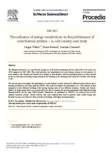
observation by showing that pentacene deposited on sputtered SiO2 grew with a different crystal morphologies depending on the dielectric surface roughness, the smoother surface improving the OFET device performance. In contrast, Shin et al.8 found that a variation of roughness in a polymethylmetacrylate layer had a little effect on the charge carrier mobility in pentacene based OFETs. The process of SiO2 growth has been optimized to enable virtually defect-free surfaces to be obtained. However, the presence of even small amounts of surface defects in the form of Si–OH groups, adsorbed water, or alkali ions can negatively influence the performance of OFETs, increasing the hysteresis and shifting the threshold voltage.9,10 Despite the SiO2 dielectric constant, k, of approximately 3.9, transistors with charge carrier mobility FET greater than 1.5 cm2 / V s were demonstrated,11 showing the potential for even higher values of FET if low-k dielectrics were to be employed.9,12,13 Here we report the influence of the SiO2 surface energy on the performance of transistors, based on highly ordered zone-cast tetrakis-共octadecylthio兲-tetrathiafulvalene 共TTF4SC18兲 layers. The zone-casting technique consists of continuous supply of an organic material solution, via a stationary nozzle, onto a moving substrate 共see Fig. 1兲. The zonecasting apparatus allows full control of deposition conditions by modification of several parameters.14 These include the solvent type, solution concentration, temperature of substrate and solution, substrate velocity, solution dosing rate, and meniscus height. Previously we have demonstrated, using crystalline perylene derivative and liquid crystalline hexabenzocoronenes, that the zone-casting technique is a suitable way of producing large area, uniaxially aligned thin films of OSCs.15 TTF materials have been shown to be very promis-
104, 054509-1
© 2008 American Institute of Physics
Downloaded 16 Sep 2008 to 155.250.129.25. Redistribution subject to AIP license or copyright; see http://jap.aip.org/jap/copyright.jsp
054509-2
J. Appl. Phys. 104, 054509 共2008兲
Miskiewicz et al.
FIG. 2. 共Color online兲 Surface morphology 共amplitude image兲 of highly oriented zone-cast TTF-4SC18 layer prepared on Si substrate with CVD 共left兲 and thermally grown 共right兲 SiO2; arrow indicates the casting direction.
FIG. 1. 共Color online兲 Schematic view of the zone-casting equipment and chemical structure of TTF-4SC18.
ing materials for the preparation of solution-processed OFETs, and single crystal OFETs based on TTFs have shown mobilities of up to 1.4 cm2 / V s 共Refs. 16–19兲. Recently, OFETs obtained from zone-cast layers of TTF-4SC18 showed a charge carrier mobility close to 0.1 cm2 / V s.20,21
mally grown SiO2 with capacitance Cox = 11 nF/ cm2 共Cemat Silicon, Poland兲. The surface of the substrates was cleaned with chloroform then with isopropyl alcohol and dried with nitrogen. Contact angle measurements were performed with KRUSS DSA10 system with water and diiodomethane. Surface energy was calculated with Owens–Wendt method, implemented in KRUSS software. III. RESULTS AND DISCUSSION
共1兲
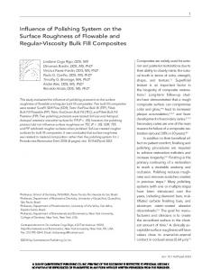
Although in literature it has been demonstrated that the surface roughness is higher for CVD SiO2 than for thermally grown SiO2, all the substrates investigated in our experiments were shown to possess a similar surface morphology, with root-mean-square roughness equal to 2 Å determined by AFM inspection for a 10⫻ 10 m2 scan area. However, contact angle measurements revealed considerable differences in the SiO2 surface energy of 40.1 mN/m for thermally grown SiO2 and 51.8 mN/m for CVD SiO2. The contact angle measurements of zone-cast TTF-4SC18 layers on Si/ SiO2 substrate demonstrated that its surface energy is lower than that of silicon dioxides equal to 20.5 mN/m. The AFM images 共Fig. 2兲 reveal a little visible difference in surface textures of the TTF-4SC18 films, zone cast on the two kinds of SiO2 substrates. In both cases the orientation imposed by the casting direction is well defined; the surface of the films is smooth in the casting direction, while in the perpendicular direction terraces with step heights of approximately 4–5 nm of several micrometers in width are formed. XRD measurements 共Fig. 3兲 indicate that a highly ordered and layered structure exists in TTF-4SC18 films zone cast on thermal SiO2 substrate. However a noticeable difference in the interlayer spacing d was observed; for the CVD
where W is the channel width 共mm兲, L is the channel length 共mm兲, Cox is the capacitance of insulator per unit area 共nF/ cm2兲, UGS is the gate-source voltage 共V兲, UT is the threshold voltage 共V兲, and IDS is the drain-source current 共A兲. In all the calculations the IDS values were read for drainsource voltage UDS = −40 V and UGS = −40 V. All experiments were carried out in dust-free air atmosphere. Two kinds of highly doped n-type silicon wafers were used as substrates for the zone-cast films: with 100 nm Si3N4 followed by 50 nm SiO2 as a dielectric layer with capacitance Cox = 21 nF/ cm2, both obtained by a PECVD method 共CVD SiO2, Wafernet, USA兲, or with 310 nm thick layer of ther-
FIG. 3. X-ray diffractogram of TTF-4SC18 thin film zone cast on the thermally grown SiO2 substrate.
II. EXPERIMENTAL
A 2 mg/ml solution of TTF-4SC18 共Fig. 1兲 synthesized, as previously described,20 in toluene was continuously supplied through the 3 cm wide nozzle onto a substrate moving with a speed of 25 m / s. Substrate and nozzle were independently thermally stabilized at 80 and 75 ° C, respectively. The dimensions of the TTF-4SC18 layers obtained in this way were 3 ⫻ 10 cm2. Atomic force microscopy 共AFM兲 images were taken with a SOLVER PRO scanning probe microscope 共NT-MDT, Russia兲 in resonant mode. Room temperature powder x-ray diffraction 共XRD兲 patterns were collected using a PANalytical X’Pert Pro MPD diffractometer. Divergent optics were used in the Bragg–Brentano 共flat-plate sample兲 geometry. Bottom gate top contact FETs were prepared by vacuum evaporation of 150 nm thick gold electrodes through a shadow mask, creating a channel with 100 m length and 2 mm width oriented parallel to the casting direction. Electrical characteristics were measured using two Keithley 2410 source-measuring units, and charge carrier mobility FET was calculated in the saturation regime from the standard equation IDS = FET共W/2L兲Cox共UGS − UT兲2 ,
Downloaded 16 Sep 2008 to 155.250.129.25. Redistribution subject to AIP license or copyright; see http://jap.aip.org/jap/copyright.jsp
054509-3
J. Appl. Phys. 104, 054509 共2008兲
Miskiewicz et al.
of 0.2 cm2 / Vs. In all tested devices the drain current modulation was in the range of 103 – 104 共CVD SiO2兲 and 104 – 105 共thermal SiO2兲 with turn-on voltage ranging from −10 to −15 V, independent of the substrate origin 共see Fig. 2兲. Due to uniformity of the uniaxially aligned TTF-4SC18 zone-cast layer, the influence of the crystal size on the charge carrier mobility can be excluded. Ordered crystals observed in AFM measurements are longer than the channel length, independent of the substrate origin. In OFET transfer curves one can see that the turn-on voltage value is similar for both substrates. This indicates that charges, which might be trapped in PECVD processes,21 are not crucial for the OFETs investigated. The difference in performance of the devices based on the two kinds of SiO2 is related to two factors: 共a兲 FIG. 4. Output characteristics of FETs based on zone-cast TTF-4SC18 layer prepared on Si substrate with 共a兲 CVD SiO2 and 共b兲 thermally grown SiO2; channels L and W are equal to 100 m and 2 mm, respectively, for each device.
SiO2, d = 41.8 Å 共Ref. 20兲, while for the thermally grown SiO2, d = 40.8 Å. These values are in agreement with the heights of steps seen in AFM images, indicating that the terraces are monolayers of vertically oriented TTF-4SC18 molecules. However, these values are lower when compared to the molecule length of 53 Å, explained by the fact that the molecules in the layers are arranged with their long axis oblique to the surface.20 The difference in the d values suggests that different SiO2 surfaces induce slightly different molecular packings with a different tiltings of the TTF4SC18 molecules with respect to the surface, probably due to the differences in the surface energy. Electrical characterization of OFET devices made from TTF-4SC18 layers zone cast on two types of the SiO2 substrates 共see Figs. 4 and 5 with output and transfer characteristics, respectively兲 revealed that FET differs by a factor of 30. In the transistors prepared on CVD SiO2, an average FET of 0.006 cm2 / V s is found, while when prepared on thermally grown SiO2 the mobility reaches the average value
FIG. 5. 共Color online兲 Transfer characteristics of FETs based on zone-cast TTF-4SC18 layer prepared on Si substrate with CVD SiO2 共black, dashed line, FET = 0.006 cm2 / V s兲 and thermally grown SiO2 共blue, solid line, FET 0.12 cm2 / Vs兲; channels L and W are equal to 100 m and 2 mm, respectively, for each device.
共b兲
The first factor is the difference in the molecular arrangement of the TTF-4SC18 molecules caused by the difference in the surface energy between the dielectric and the semiconductor. As it was previously shown in TTFs and other OSCs, the crystal structure strongly determines the resulting device performances.22 For the TTF-4SC18 layer on thermally grown SiO2 the difference in the surface energy is 19.6 mN/m, while in the case of CVD SiO2 it is 31.3 mN/m. A smaller mismatch in surface energy may result in better molecular packing and consequently more efficient charge transport in a few TTF-4SC18 layers, critical for the OFET performance at the dielectric-OSC interface. In our experiments differences in the crystal structure are relatively small but have contribution into the device performance. Similar influences in the surface energy of the dielectric were observed by Chou et al.23 in pentacene based transistor deposited on polyimide coated SiO2. The second factor is the influence of the energetic disorder at the OSC-dielectric interface due to the dielectric surface energy. It was shown in the literature that dielectric constant k of employed dielectric layer can have serious impact on the OFET performance— decrease in FET from 20 to 1.5 cm2 / V s when k increases from 1 to 25 共Ref. 12兲 for rubrene single crystal devices—and the reason for that behavior is related to enhancement of carrier localization at the OSCdielectric interface.24,13 Surface energy of the insulating layer can mirror the bulk properties because high-k materials have usually higher surface energy than low-k ones. As it was demonstrated in the literature,9,24–28 dielectric surface modifications resulting in lower surface energy lead to better performance of the OFET, although in some cases the changes in morphology make it difficult to distinguish morphology and surface energy effects 共lower surface energy usually leads to smaller crystal grown on the dielectric; nevertheless, total performance is higher for bigger crystal on the higher surface energy兲. In our case we are able to prepare very similar TTF-C18 layer on different surface energy dielectrics. CVD SiO2 used in our experiment is thick enough 共50 nm兲 to shield OSC from higher k
Downloaded 16 Sep 2008 to 155.250.129.25. Redistribution subject to AIP license or copyright; see http://jap.aip.org/jap/copyright.jsp
054509-4
Si3N4; nevertheless it can possess less uniform surface in terms of energy fluctuation that can localize charge carrier at the interface and lower the mobility. Thermally grown SiO2, employed as the dielectric with lower surface energy, decreases the energetic disorder and thus enables to achieve higher performance OFETs. IV. SUMMARY
In summary we have demonstrated that the surface energy of the dielectric can have large impact on the performance of FETs based on TTF-4SC18. Average charge carrier mobility was increased from 0.006 to 0.2 cm2 / V s when the surface energy of the employed SiO2 dielectric surface was decreased 共from 51.8 to 40.1 mN/m兲. The performance of the OFETs produced on SiO2 of different origin is more complex, and other factors such as surface energy and method of OSC deposition, in addition to the surface roughness, should be taken into account. The achieved FET of 0.2 cm2 / V s is among the best results published for large area solutionprocessed OFETs prepared and measured in air, especially taking into account the reproducibility and uniformity of zone-cast layers. ACKNOWLEDGMENTS
This work was partially financially supported through the EC Integrated Project NAIMO 共Grant No. NMP4-CT2004-500355兲, DGI Spain 共Grant No. CTQ2006-06333/ BQU兲, Dursi Catalunya 共Grant No. 2005 SGR 00591兲, NoE PolyNet 共Grant No. UE ICT 214006兲, MNiI 共Grant No. T08E 1327兲, and Poland and KTP 共Grant No. 1326-A02兲, United Kingdom. 1
J. Appl. Phys. 104, 054509 共2008兲
Miskiewicz et al.
R. A. Street, W. S. Wong, S. E. Ready, M. L. Chabinyc, A. C. Arias, S. Limb, A. Salleo, and R. Lujan, Mater. Today 9, 32 共2006兲. 2 S. M. Sze, Semiconductor Devices: Physics and Technology, 2nd ed. 共Wiley, New York, 2001兲. 3 Y. Y. Lin, D. J. Gundlach, S. F. Nelson, and T. N. Jackson, IEEE Electron Device Lett. 18, 606 共1997兲. 4 A. Salleo, M. L. Chabinyc, M. S. Yang, and R. A. Street, Appl. Phys. Lett.
81, 4383 共2002兲. A. Di Carlo, F. Piacenza, A. Bolognesi, B. Stadlober, and H. Maresch, Appl. Phys. Lett. 86, 263501 共2005兲. 6 D. Knipp, R. A. Street, A. Völkel, and J. Ho, J. Appl. Phys. 93, 347 共2003兲. 7 S. Steudel, S. De Vusser, S. De Jonge, D. Janssen, S. Verlaak, J. Genoe, and P. Heremans, Appl. Phys. Lett. 85, 4400 共2004兲. 8 K. Shin, C. Yang, S. Y. Yang, H. Jeon, and C. E. Park, Appl. Phys. Lett. 88, 072109 共2006兲. 9 J. Veres, S. Ogier, G. Lloyd, and D. de Leeuw, Chem. Mater. 16, 4543 共2004兲. 10 L.-L. Chua, J. Zaumseil, J.-F. Chang, E. C.-W. Ou, P. K.-H. Ho, H. Sirringhaus, and R. H. Friend, Nature 共London兲 434, 194 共2005兲. 11 S. Subramanian, S. K. Park, S. R. Parkin, V. Podzorov, T. N. Jackson, and J. E. Anthony, J. Am. Chem. Soc. 130, 2706 共2008兲. 12 A. F. Stassen, R. W. I. De Boer, N. N. Iosad, and A. F. Morpurgo, Appl. Phys. Lett. 85, 3899 共2004兲. 13 I. N. Hulea, S. Fratini, H. Xie, C. L. Mulder, N. N. Iossad, G. Rastelli, S. Ciuchi, and A. F. Morpurgo, Nat. Mater. 5, 982 共2006兲. 14 J. Ulanski, E. El Shafee, A. Tracz, G. Debrue, and R. Deltour, Synth. Met. 35, 221 共1990兲. 15 P. Miskiewicz, A. Rybak, J. Jung, I. Glowacki, J. Ulanski, Y. Geerts, M. Watson, and K. Mullen, Synth. Met. 137, 905 共2003兲. 16 M. Mas-Torrent, M. Durkut, P. Hadley, X. Ribas, and C. Rovira, J. Am. Chem. Soc. 126, 984 共2004兲. 17 M. Mas-Torrent and C. Rovira, J. Mater. Chem. 16, 433 共2006兲. 18 X. Gao, W. Wu, Y. Liu, W. Qiu, X. Sun, G. Yu, and D. Zhu, Chem. Commun. 共Cambridge兲 2006, 2750. 19 I. Doi, E. Miyazaki, K. Takimiya, and Y. Kunugi, Chem. Mater. 19, 5230 共2007兲. 20 P. Miskiewicz, M. Mas-Torrent, J. Jung, S. Kotarba, I. Glowacki, E. Gomar-Nadal, D. B. Amabilino, J. Veciana, B. Krause, D. Carbone, C. Rovira, and J. Ulanski, Chem. Mater. 18, 4724 共2006兲. 21 P. Wu, G. Saito, K. Imaeda, Z. Shi, T. Mori, T. Enoki, and H. Inokuchi, Chem. Lett. 15, 441 共1986兲. 22 M. Mas-Torrent, P. Hadley, S. T. Bromley, X. Ribas, J. Tarres, M. Mas, E. Molins, J. Veciana, and C. Rovira, J. Am. Chem. Soc. 126, 8546 共2004兲. 23 W. Y. Chou, C. W. Kuo, H. L. Cheng, Y. R. Chen, F. C. Tang, F. Y. Yang, D. Y. Shu, and C. C. Liao, Appl. Phys. Lett. 89, 112126 共2006兲. 24 J. Veres, S. D. Ogier, S. W. Leeming, D. C. Cupertino, and S. M. Khaffaf, Adv. Funct. Mater. 13, 199 共2003兲. 25 S. Y. Yang, K. Shin, and C. E. Park, Adv. Funct. Mater. 15, 1806 共2005兲. 26 S. E. Fritz, T. W. Kelley, and D. Frisbie, J. Phys. Chem. B 109, 10574 共2005兲. 27 C. S. Kim, S. J. Jo, S. W. Lee, W. J. Kim, H. K. Baik, and S. J. Lee, Adv. Funct. Mater. 17, 958 共2007兲. 28 M. Zirkl, A. Haase, A. Fian, H. Schön, C. Sommer, G. Jakopic, G. Leising, B. Stadlober, I. Graz, N. Gaar, R. Schwödiauer, S. Bauer-Gogonea, and S. Bauer, Adv. Mater. 共Weinheim, Ger.兲 19, 2241 共2007兲. 5
Downloaded 16 Sep 2008 to 155.250.129.25. Redistribution subject to AIP license or copyright; see http://jap.aip.org/jap/copyright.jsp