Modern Methods and Advances in Structural Engineering and Construction Cheung, S. O., Yazdani, S., Ghafoori, N., and Singh, A. (eds.) ISEC-6, Zürich, June 21–26, 2011
DESIGN ANALYSIS OF SUPERPOSED AQUEDUCT WITH LONGITUDINAL PPCBS AND SEGREGATE CAST-IN-SITU RCF S.B. Zhao, S.W. Pei and X.J. Liang School of Civil Engineering and Communication, North China Institute of Water Conservancy and Hydroelectric Power, Zhengzhou, P.R. China. E-mail:
[email protected] Combined with the structural design of left-shore drainage aqueducts in China South-to-north Water Transfer Project, the superposed aqueduct with longitudinal precast prestressed concrete beams (PPCBs) and segregate cast-in-situ reinforced concrete flume (RCF) was drafted, 11 longitudinal T-sectional PPCBs with flange width of 2.1m and height of 1.45m were composited to support the cast-in-situ RCF in span of 17.0m with total width of 25.6m and height of 2.0m, the subplate of RCF is segregated by asphalt layer on the top surface of PPCBs. The threedimensional finite element models were built to study the normal service behaviors of the large superposed aqueduct compared with that of the entire cast-in-situ structure. Based on the calculation, the stresses and displacements of longitudinal PPCBs, the subplate of RCF in different loading cases of self-weight load, design water load and check water load are analyzed. The results provide valuable reference for designing the same kind of aqueduct. Keywords: Aqueduct, Superposed structure, precast prestressed concrete, cast-in-situ reinforced concrete, longitudinal beam, flume, segregate layer, finite element analysis.
1
Introduction
Considering that the wide and shallow section of aqueduct should be selected to suit the conflux drainage requirements of the many river/channels scatter region and the sloping water region on the left shore, and the large span prestressed concrete structure should be selected to avoid setup the middle pier in the backbone canal and abate the unfavorable effect on the water transfer ability of backbone canal, the prestressed concrete aqueduct with multi-longitudinal beams becomes the prefer structure for the left-shore drainage aqueduct of China South-to-north Water Transfer Project in Hebei province (Zhao et al, 1999 and 2003). Based on the practical situations, the aqueduct can be constructed with different
1
procedures such as casting in-situ of the entire structure or precasting the longitudinal beams firstly and casting in-situ the superposed reinforced concrete flume. It is necessary to study the effect of constructing procedures on loading behaviors of aqueduct. Therefore, combined with the actual engineering design and by means of the 3D FEM, the paper analyzes the loading behaviors of aqueducts superposed by cast-in-situ reinforced concrete flume (RCF) with segregate asphalt layer on top surface of precast prestressed concrete beams (PPCBs). 2
Basic Facts of Aqueduct
Zhao Guzhuang drainage aqueduct is the two spans prestressed concrete structure with longitudinal beams, each span is 17.0m, the
Design Analysis of Superposed Aqueduct with longitudinal PPCBs and Segregate Cast-in-situ RCF S.B. Zhao, S.W. Pei, and X.J. Liang
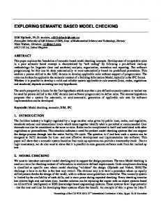
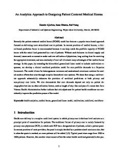
cross section of drainage flume is width of 25.0m and height of 1.8m, the design water depth is 1.33m, the check water depth is 1.68m. Other design parameters are first classes of building level and structural safety grade, strength grade C50 of concrete, HRB335 steel bar for load-bearing reinforcement, HPB235 steel bar for constructional reinforcement, post-tensioning prestressed system, high strength and low relaxation strand in diameter of 15.24mm tensioned with control stress σcon=0.75fptk =1395MPa after the concrete reaching the 100% design strength, clamping pieces anchorage, plastic corrugated pipe and vacuum assisted grouting. The thickness of concrete covering reinforcements is 25mm for sidewall and subplate, 35mm for longitudinal beams. The cross sectional shape and dimensions of superposed aqueduct is shown in Figure 1, each crossbeam in width of 0.2m and height of 1.3 m is set with distance of 4.5m or 3.6m along the span, which is linked by cast-in-situ reinforced concrete node. The strands of longitudinal PPCBs are arranged by two rows, which are all 7фj15.24 with linear add curve shapes shown in Figure 2.
Figure 1. Cross-section of superposed aqueduct (unit: cm).
stresses without regarding to the loss of prestress. Second, hoist the PPCBs and cast the crossbeam nodes in-situ, consider the first loss of prestress, taking the hoisting dynamic factor as 1.5 for checking the sectional stresses. Third, spray emulsified asphalt and lay the asphalt felt layer. Fourth, cast concrete in-situ of the flume subplate and sidewall up to height of 300mm above stiffener, considering the whole loss of prestress. Finally, cast the remnant concrete of side wall. To study the effects of construction procedures and segregate asphalt layer on normal service behaviors of SA, the entire cast-in-situ aqueduct (EA) with the same dimensions and reinforcements as SA is comparatively analyzed. According to the current design code (SL 191-2008), the aqueduct is in the second class environment, the crack is controlled by normally un-cracked requirement. To simplify the explanation, it is named that the loading cases C1, C2 and C3 correspond to the selfweight, the self-weight add design water load and the self-weight add check water load respectively. In view of that the self-weight is the long-term effect, and the design and check water loads are all short-term effects, the tensile stress should not appear at the section edges in loading case C1. In the loading cases C2 and C3, the limit coefficient of tensile stress is 0.7 for concrete of PPCBs, crossbeams and RCF subplate and 0.85 for concrete of sidewall, which correspond to the tensile stresses 1.85MPa and 2.24MPa respectively. 3
Figure 2. Strands arrangment of PPCBs (unit: cm).
The construction process of superposed aqueduct (SA) is made referenced prior studies by Zhao et al (1999, 2001). First, precast the PPCBs, checking the sectional
2
Method of Analysis
The numerical models of aqueduct are made of the 3D finite element method in software ANSYS, the concrete and the segregate asphalt layer are simulated by the block element Solid45, the strands are simulated by the space bar element Link8. The pretensioning forces were applied point by point on the Link 8 elements according to the
Modern Methods and Advances in Structural Engineering and Construction Cheung, S. O., Yazdani, S., Ghafoori, N., and Singh, A. (eds.) ISEC-6, Zürich, June 21–26, 2011
Disscussion of Analytical Results
According to the calculation, the aqueduct satisfies the requirements of design code in the prestressed construction period and the hoisting period of PPCBs. Therefore, only the stresses and deformations of aqueduct after construction are compared under the actions of self-weight and design or check water loads. 4.1
Behaviors of Longitudinal Beams
-2 -1 0 1 2 3 4
Stress /MPa
2
Distance from sidebeam center /m 2.1
C1 C2
4.2
SA SA
6.3
EA EA
8.4
C3
10.5 12.6
SA
Distance from sidebeam center/m
2.1
4.2
6.3
8.4
1
Distance from support center /m 2 3 4 5 6 7
8
9
1
Distance from support center /m 2 3 4 5 6 7
8
9
1
Distance from support center /m 2 3 4 5 6 7
SA
bottom
top
EA
bottom
8
9
top
Figure 4. Variations of normal stresses along span direction at the top and bottom edges of 6# PPCB.
EA
1 0
2 1 0 -1 -2 -3 -4 2 1 0 -1 -2 -3 -4 2 1 0 -1 -2 -3 -4
Stress /MPa
Deflection /mm
Figure 3 shows the variations of mid-span deflections and normal stresses at sectional bottom edge of PPCBs. Figure 4 shows the variations of normal stresses in span direction at the top and bottom edges of 6# PPCB corresponding to the loading cases C1, C2 and C3 accordingly.
Stress /MPa
4
of PPCBs are affected in some extent by the segregate asphalt layer, the PPCBs of EA obtains better prestress effect with larger midspan arch deflection in range of 1.06mm to 1.45mm and larger compressive prestress in range of 2.69MPa to 2.88MPa. The whole compressive prestress states are there on the middle spans. The obvious differences take place in the length of 0.8 m near each ends, where the maximum tensile stress of 0.17 MPa only occurs on top surfaces of PPCBs of EA, but the maximum tensile stresses of 2.07 MPa and 1.34 MPa appear on top and bottom surfaces of PPCBs of SA.
Stress /MPa
calculation of the loss of prestress along the strands. The ‘live and death element’ was used to simulate the concrete in different construction process. The contribution of ordinary reinforcements on structural stiffness was considered by the elastic modulus of uniform reinforced concrete (Zhao et al, 1999).
10.5 12.6
-1 -2 -3
Figure 3. Variations of mid-span deflections and sectional bottom edge normal stresses of PPCBs.
From the variations of deflections and stresses under loading case C1, the prestresses
3
From the variations of deflections and stresses under loading case C2, the PPCBs of EA are in whole sectional compressive states with stress in range of 0.15MPa to 1.31MPa and small deflections in range of 0.31mm to 0.99mm. The maximum tensile stresses of 2.15MPa and 0.86MPa appear on the top and bottom surfaces of PPCBs of SA in length of 0.8m near each ends, and 0.48MPa on the bottom surface in middle span. From the variations of deflections and
Design Analysis of Superposed Aqueduct with longitudinal PPCBs and Segregate Cast-in-situ RCF S.B. Zhao, S.W. Pei, and X.J. Liang
It is noted that the subplate of RCF is almost in unstressed state in transversal and longitudinal direction under loading case C1. Figure 5 shows the variations of stresses at top and bottom edges of subplate longitudinal section along flange edge of 6# PCCB corresponding to the loading cases C2 and C3 accordingly. The subplates are almost in compressive states in longitudinal direction, but the compressive stresses on subplate of SA are smaller than that of EA.
1
Stress /MPa
1
bottom bottom
-0.25
top top
Distance from support center /m 2 3 4 5 6 7 8 9
0 -1 bottom bottom
top
2.1
Distance from support center /m 4.2 6.3 8.4 10.5
12.6
0.0 -0.2 SA
0.2
bottom
top
EA
bottom
top
2.1
Distance from support center /m 4.2 6.3 8.4 10.5
12.6
0.0 -0.2 -0.4
SA
bottom
0.25
top
EA
bottom
top
2.1
-0.25 0.25
EA
Figure 5. Variations of stress in span direction at top and bottom edges of subplate longitudinal section along flange edge of 6# PPCB.
4
12.6
top
12.6
0.00 -0.25 SA
bottom
top
EA
bottom
top
Distance from support center /m 2.1 4.2 6.3 8.4 10.5
12.6
0.00 -0.25 -0.50
Figure 6 and Figure 7 show the variations
bottom
Distance from support center/m 2.1 4.2 6.3 8.4 10.5
0.25
top top
Distance from support center /m 4.2 6.3 8.4 10.5
0.00
-0.50 SA
bottom
0.4
-2 -3 EA
EA
0.2
-0.4
Stress /MPa
SA EA
12.6
0.00
0.4
Stress /MPa
0
-3
Distance from support center /m 4.2 6.3 8.4 10.5
Figure 6. Vairations of transversal stress at top and bottom edges of 1/4-span section.
Distance from support center /m 1 2 3 4 5 6 7 8 9
-1 -2
2.1
Stress /MPa
Stress /MPa
1
Stress /MPa
Behaviors of Subplate
0.25
Stress /MPa
4.2
of transversal stresses at top and bottom edges of 1/4-span section and mid-span section of subplate respectively, in which from the upper to lower corresponds to the loading cases C1, C2 and C3. Obviously, the loading behavior of subplate is just like a continuous beam supported on the PPCBs in transversal direction. Because the subplate of EA bears water loads together with the flange of PPCBs, there are smaller tensile stress at the bottom surfaces of subplate accompanying with the compressed top surfaces except tensioned in width about 0.5m near sidewall with maximum of 0.25MPa in loading case 3.
Stress /MPa
stresses under loading case C3, the top surface of PPCBs of EA is in whole compressive states, and the maximum tensile stress of 0.56MPa appears on the bottom surface of middle span. The maximum tensile stresses of 2.17MPa and 0.79MPa appear on the top and bottom surfaces of PPCBs of SA in length of 0.8 m near each ends, and 1.23MPa on the bottom surface in middle span. Obviously, the deformation concerted ability of PPCBs bearing water loads together with RCF is weakened by the segregate layer of SA, which results in the decrease of total depths and the smaller flexural stiffness of the PPCBs.
SA
bottom
top
EA
bottom
top
Figure 7. Variations of transversal stress at top and bottom edges of mid-span section
Modern Methods and Advances in Structural Engineering and Construction Cheung, S. O., Yazdani, S., Ghafoori, N., and Singh, A. (eds.) ISEC-6, Zürich, June 21–26, 2011
On the contrary, the RCF of SA carries water loads on its own firstly, the subplate directly bears the tensile force resulted from the water loads on sidewall, which leads many longitudinal sections of subplate into the whole tensile state. The width of subplate near sidewall with larger tensile stress at top edges becomes longer, and the maximum tensile stress of 0.58 MPa tends on the top edges in loading case 3. 4.3
Behaviors of Sidewall
Figure 8 shows the variations of vertical stress at internal surface and lateral displacement in height of sidewall at 1/4-span section and mid-span section in loading cases C2 and C3. Obviously, while the aqueduct builds with segregate layer, the deformation of sidewall is only confined by the subplate, the vertical tensile stresses at internal surface of sidewall increase, the lateral displacements are all to the internal of RCF with smaller values at 1/4span section and larger values at mid-span section. 1.8
1.8 SA EA
C2 C2
C3 C3
1.2 0.9 0.6
0.9 0.6
0.0 0.1 0.2 0.3 0.4 0.5 0.6 Stress /MPa 1.8
1.5
1.5
1.2 0.9
0.0
SA EA
C2 C2
C3 C3
0.1 0.2 0.3 0.4 Displacement /mm
Height /m
1.8
0.3
C3 C3
1.2
0.0 0.1 0.2 0.3 0.4 0.5 0.6 Stress /MPa
0.6
C2 C2
0.3
0.3
Height /m
SA EA
1.5
Height /m
Height /m
1.5
1.2 0.9 0.6 0.3 0.0
SA EA
C2 C2
C3 C3
0.1 0.2 0.3 0.4 Displacement /mm
Figure 8. Variations of internal surface stress and lateral displacement of side wall in height.
5
5
Conclusions
The segregate layer between top surface of PPCBs and RCF may result in the larger mid-span displacements and tensile stresses of PPCBs. The segregate layer brings the RCF into bearing water loads on its own firstly, which results in the subplate directly carrying the tensile force due to the water loads on sidewall, and the sidewall only confined by subplate. Many longitudinal sections of subplate are in the whole tensile state, the width of subplate near sidewall with larger tensile stress at top edges becomes larger, vertical tensile stresses with larger values appear on the internal surface of sidewall. However, the aqueduct with segregate layer still satisfies the design requirements. References Zhao S.B., Hu Z.Y. and Li X.K., Experimental Investigation of Large Reinforced Concrete Aqueduct with Multi-longitudinal Beams, Journal of Hydroelectric Engineering, 18 (3), 42-52, Sept, 1999. Zhao S.B., Zhang L.M. and Li S.Y., Experimental Investigation of Large Prestressed Concrete Aqueduct, Journal of Hydroelectric Engineering, 22 (1), 42-52, March, 2003. Zhao S.B. and Zhang X.Z., Design principle and application of concrete superposed structures, China Hydroelectric Press, Beijing, 2001. Zhao S.B., Chen W.Y. and Huang H.F., Study of Congruent Structure Design of Prestressed Concrete Aqueduct in Water Diversion from the Yangtze River into the Yellow River, Yellow River, 21 (2), 35-37, Feb, 1999. SL 191-2008, Design code for hydraulic concrete structures, China Hydroelectric Press, Beijing, 2008. Zhao S.B., Li X.K. and Zhao P., On the Design Method for Large Reinforced Concrete Aqueduct with Multi-longitudinal Beam, Journal of Hydraulic Engineering, 30 (4), 35-39, April, 1999.
Modern Methods and Advances in Structural Engineering and Construction Cheung, S. O., Yazdani, S., Ghafoori, N., and Singh, A. (eds.) ISEC-6, Zürich, June 21–26, 2011
6