Instrumentation and Control of a High Power BLDC Motor for Small Vehicle Applications Alexander Rowe1, Gourab Sen Gupta1, Serge Demidenko2 1
School of Engineering and Advanced Technology, Massey University, Palmerston North, New Zealand School of Electronics and Computer Engineering, RMIT International University Vietnam
[email protected],
[email protected],
[email protected]
Abstract—Brushless DC (BLDC) motors are becoming an increasingly popular motor of choice for low powered vehicles such as mopeds, power assisted bicycles, mobility scooters, and in this reported application, motorised mountain boards. With rapid developments in technology, high energy density batteries such as Lithium-ion Polymer batteries are becoming more affordable and highly suitable for such vehicles due to the superior charge rate and light weight of the lithium chemistry batteries. This combined with the high power, light weight, and low cost BLDC motor results in the BLDC motor being a very favourable solution over an internal combustion engine for low power vehicles with power requirements of up to 7kW. A BLDC motor controller was developed specifically for the motorised mountain board application. The motor controller is a sensored BLDC motor controller which takes inputs from Hall Effect sensors to determine the rotor position. Many other sensors are used to monitor the variables that are critical to the operation of the motor controller such as the motor phase current, battery voltage, motor temperature, and transistor temperature. The reported system is further enhanced by several additional features such as output for an LCD screen, regenerative braking, timing advance, cruise control, and soft start functions. These topics are discussed briefly in this paper.
A sensorless controller requires the motor to produce a measureable back EMF for the motor controller to be able to determine the position of the rotor and therefore cannot provide smooth commutation at start up and low speeds. In contrast, a sensored BLDC motor controller uses position sensors and therefore is able to determine the rotor position at any speed. This allows for smooth commutation during start up. A sensored BLDC motor controller was built for this reason. II.
ELECTRICAL SYSTEM OVERVIEW
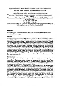
A mixed-signal field programmable microcontroller, the Silicon Laboratories C8051F020, has been used to control the motor driver circuit according to a range of inputs from various sensors. Custom made software was programmed in C which runs on the microcontroller. This software determines the operation of the motor controller. Fig. 1 shows the functional blocks of the motor controller. The motor controller uses a three phase H-bridge to drive the motor. This circuit was chosen because it allows for four quadrant operation of the motor, as well as coasting. Fig. 2 shows the schematic diagram of the three phase H-bridge.
Keywords- sensored BLDC motor controller, regenerative braking, timing advance, electric skateboard, Hall sensors I.
INTRODUCTION
A motorised mountain board allows users to take the extreme sport of mountain boarding, which is normally limited to downhill use only, to flat and uphill surfaces. This gives the users a much wider choice of locations where they can use the mountain board. A BLDC outrunner motor has been used for this application. An outrunner motor was chosen for its low speed (130 RPM/v), high torque characteristics which reduces the gearing requirements; a 3.8:1 gear ratio is used which is achieved in a direct chain drive. The motor is a Turnigy C80100-130 which has a power rating of 6.5 kW. This amount of power is sufficient to drive small vehicles to speeds of approximately 70 km/hr; however the gearing and battery voltage has been selected to limit the mountain board to 50 km/hr. Consequently, the torque at the wheels is increased and is sufficient to allow the motorised mountain board to climb steep hills.
978-1-4577-1772-7/12/$26.00 ©2012 IEEE
Figure 1
Overview of the major components of the motor controller
Figure 2. Three phase H-bridge circuit for driving a BLDC motor
The motor controller is built to meet the specifications of the motor - the motor controller should be capable of supplying 130A at 48V for bursts of 5s and be able to supply at least 40A continuously. The devices of choice for the switches in the Hbridge are N-channel metal oxide semiconductor field effect transistors (N-MOSFETS). These were chosen for their low cost and their ability to share current relatively evenly when paralleled together [1]. To achieve the target current capability of 130A, two N-MOSFETS are used in parallel for each of the six switches in the three phase H-bridge. A. Motor Driver Circuit A gate driver IC is used between the microcontroller and the gates of the MOSFETS for three reasons: •
To step up the 3.2V logic signal from the microcontroller to a 12V signal for the low side transistors in order to saturate the MOSFET
•
To provide a charge pump circuit for driving the gate of the high side transistors to 12V above the voltage on the source pin in order to saturate the MOSFETS
•
To provide shoot-through protection with programmable dead time for the three phase H-bridge
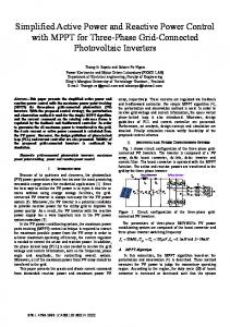
Gate resistors between the output from the gate driver IC and MOSFET gate are used to slow the switching times of the transistors. This is to reduce the rate of change of current (di/dt) through the motor windings [2]. The self inductance of the windings causes an induced voltage across the winding that is proportional to the rate of change of current when the transistors are switched on and off. This induced voltage can cause the transistors to experience a voltage that exceeds the Vdss rating, causing them to blow. These gate resistors are arranged in a way to reduce ringing issues with the paralleled transistors [3]. Fig 3 shows the schematic diagram for the gate resistor circuit that will reduce ringing in a half bridge circuit. This can be extended if more transistors are required in parallel. Slowing the switching time of the transistors alone is not enough to protect the transistors from blowing; bus capacitors are also used to absorb the voltage spikes [2]. Low equivalent series resistance (ESR) capacitors are required because the frequency of the voltage spike is very high (around 50 MHz). Standard electrolytic capacitors are not fast enough to absorb transient voltages of such frequencies.
Figure 3. Circuit diagram for gate resistors to minimize the effect of ringing in the MOSFET gates
The Motor Controller circuit incorporates a Hall Effect current sensor to measure the phase current of the motor. This allows the Motor Controller to cut the power to the motor if the phase current exceeds the specified limit in order to protect the motor windings from burning out and the transistors from blowing due to the current exceeding the maximum rating. The Hall Effect current sensor output is an analogue signal that is proportional to the current flowing through a wire. A bidirectional current sensor is used in this application to allow for current measurements while regenerative braking. The Motor Controller also uses a voltage sensor circuit to take measurements of the battery voltage. If the voltage is lower than the specified minimum voltage of the battery, the motor controller will cut the power to the motor. This is important as to not over discharge the Lithium-ion Polymer battery pack which can permanently reduce the capacity of the battery [4]. Because of the wide range of operating voltages that the motor controller is able to run on (from 16V to 70V), voltage sensing is done using a simple voltage divider circuit with a low pass RC filter; a level shifter is not used. Temperature sensors are installed in the motor and on the heat sink of the transistors to allow the motor controller to cut the power to the motor if either of the temperatures exceeds a pre-defined limit. The on-board temperature sensor of the microcontroller is also used to take measurements of the microcontroller temperature. Again, the motor controller will cut the power if the microcontroller is overheating. The current sensor, voltage sensor, and temperature sensors all output analogue signals. Because these sensors are in close proximity to the power electronics in the motor driver circuit, the small signal analogue outputs from the sensors are highly susceptible to noise. For this reason, a RC low pass filter is used for each of the analogue signals to filter out the high frequency noise. Each filter is tuned to filter any noise that is of slightly higher frequency than the highest expected frequency from the sensor.
B. Regenerative braking The motor controller incorporates a simple regenerative breaking function. The amount of energy regenerated during normal use in a flat or uphill application is very little. However, because regenerative braking is the only braking method that does not simply convert kinetic energy into heat energy, which heats up the transistor heat sink and the motor, it was included in the project.
would require a dedicated microcontroller [7]. The large amount of processing is required because the microcontroller must predict when the next motor position will occur based on the speed of the motor, and then calculate the time delay between the last motor position transition and the next transition for the desired angle of advance. With this information the microcontroller can trigger the commutation at the calculated time after the previous transition.
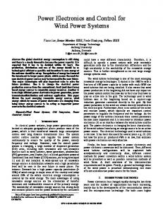
Regenerative braking is achieved by boosting the back EMF of the motor to a higher voltage than the battery voltage by using a boost converter circuit. Fig. 4 shows the schematic diagram of a basic boost converter circuit [5]
D.
This circuit is implemented without any additional hardware. It is created by using the low side transistors of the three phase H-bridge as the switching device, the motor windings as the inductor, and the high side flyback diodes as the diode in the boost converter circuit. Three of these circuits are in fact used, one for each of the three phases. The output voltage of the boost converter is controlled by varying the PWM duty cycle of the low side transistor. As the output voltage is increased, the charging current is increased which results in the braking force being increased. Therefore the braking force is controlled by reading the position of the brake lever and adjusting the duty cycle accordingly. The charging current has to be kept within specified limits to prevent damage to the battery pack. For the Lithium-ion Polymer battery pack used in this application, the maximum charging current is 20A. It was calculated that 20A of charge current provides sufficient brake power to slow down from 30 km/hr to a complete stop in 3s
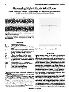
Internal position sensors In this application, a simple approach to timing advance has been taken; two sets of Hall Effect sensors have been installed inside the motor. One set is positioned for neutral timing, the other set is positioned 30° (electrical rotation) from the neutral timing set. This second set of Hall Effect sensors produce a signal for 30° advanced timing in the forward direction or 30° retarded timing in the reverse direction. This angle of advance was recommended by [8] as an optimum amount of timing advance for this motor at 5000RPM which is near the top speed of the motor when running on a 42V battery. Also, because the motor has a 12 pole stator, each pole is spaced 30° apart. This means that both the neutral timing and advanced timing set of Hall Effect sensors can conveniently be mounted in the gaps between the stator poles. Fig. 5 shows waveforms of the signals from the neutral and 30° advanced motor position sensors. The top three waveforms are from the neutral timing set and the bottom three are from the advanced timing set of motor position sensors. This shows the advanced timing transitions occurring 30° of electrical rotation before the neutral timing transitions.
Figure 4. Circuit diagram showing how the boost converter circuit is implemented using a half bridge
C. Timing Advance Timing advance is used in both brushed and brushless DC motors [6]. In brushed DC motors this is done by mechanically moving the position of the brushes relative to the motor windings. In BLDC motors, timing advance is done electronically by commutating the motor sooner than it would normally do so. Ideally, the amount of timing advance (expressed as an angle of electrical rotation) would be continuously variable from 0° at zero speed to some maximum advance angle at the maximum motor speed. This can be done with a microcontroller, however it requires much processing and
Figure 5. Waveforms from the neutral and 30° advanced motor position sensors
With this angle of timing advance, it also works out that the signal for 30° advanced timing in the reverse direction can be generated from the signal from the second set of hall sensors. This is because the signal for 30° retarded timing is identical to the 30° advanced signal when phase shifted by 60° (which is the spacing between motor position transitions). This results in the 30° retarded signal being exactly one sequence behind the 30° advanced signal. By generating this third signal, it is possible for the Motorboard to use 30° advanced timing in the
forward and reverse direction. The microcontroller is able to switch between neutral timing and advanced timing depending on the speed of the motor. The software makes use of a hysteresis by switching to advanced timing at 4800 RPM and back to neutral timing at 4700 RPM. III.
SOFTWARE DESIGN
The microcontroller is programmed with custom made software to allow for additional functions that are unique to this motor controller. The software is largely interrupt based for improved computational efficiency and reliability. Each time the microcontroller reads an analogue input, eight consecutive readings are taken and the average of these readings is calculated and used to set the new value of the variable that is being read. This helps to further reduce the effect of noise on the analogue signals from the various sensors. Distance measurements are done by counting the number of new motor positions. For this particular motor, there are 6 rotor positions in an electrical revolution, and 7 electrical revolutions in a physical revolution of the motor. With a wheel diameter of 200mm and a gear ratio of 3.8:1, it can be calculated that after 254 new motor positions, the mountain board will have travelled 1 meter. When the “new position” counter reaches 254, the distance counter is incremented by 1 m and the “new position” counter is reset to zero. Speed measurement is achieved by using one of the on board timers to time the interval between two consecutive motor position readings. The distance travelled for a single position increment is known and therefore the speed can be calculated. At high speeds, the average of eight speed readings is used for improved accuracy. Fig 6 illustrates the basic flow diagram of the motor controller software. A. Soft Start The purpose of the soft start function is to protect the motor and motor driver circuit from experiencing an over current condition during start up. This is required because when the motor is at low speed or stationary, there is little or no back EMF produced by the motor. The back EMF opposes the voltage applied to the motor terminals, therefore the voltage experienced by the motor is the difference between the supply voltage and the back EMF voltage. With no back EMF, the voltage experienced by the motor is large. The only resistance in the circuit is that of the on-resistance of the transistors (0.008 Ω) [9], the resistance of the motor windings (0.036 Ω), and the resistance of the wires which is also very low. Thus the current can reach very large levels when the motor is stationary or running at a low speed. The soft start function limits the power to the motor as a function of speed at which the motor is running. This is done by setting a maximum allowable duty cycle of 5% at zero speed and increasing this limit linearly to 100% at 1900 RPM. This function is implemented in the main loop of the program and therefore does not effect the operation of the critical interrupt based functions.
Figure 6. Basic flow diagram of the microcontroller program
B. Cruise control The cruise control function uses PI control to maintain the speed of the Motorboard at the speed set point. The set point is taken as the current speed at the time when the cruise control is activated by switching on the cruise control switch on the handheld controller. The PI controller varies the PWM duty cycle in order to maintain the speed at the set point as the load changes, i.e. when travelling up a hill. The cruise control function is deactivated then the user applies the brakes. When the user stops using the brakes, the new speed is taken as the set point. The values for the proportional factor and integral factor were found experimentally. IV.
HANDHELD CONTROLLER
The user interface for the motorised mountain board is a handheld controller. The shell of a radio controlled car transmitter was used as the base of the handheld controller. This shell was modified by stripping out the circuit board, cutting off the battery case, and mounting a LCD module into it. The trigger mechanism was retained and is used as the accelerator and brake control (pull back the trigger to accelerate, push forward to brake). There are two variable resistors (rotary potentiometers) that are also utilised; one is used to set the maximum duty cycle for the controller. This allows the maximum speed of the Motorboard to be limited by the user which is useful when someone is using the Motorboard for the first time. The other variable resistor is used to cycle through the various data that is
displayed on the LCD module. There are two switches that are used by the motor controller; one is used to turn the controller on and off, the other is used as the cruise control on/off switch. The completed Motorboard and the handheld controller are shown in Fig 7. The LCD screen is only large enough to display two lines of 16 characters. In order to display more data than would otherwise be possible, one of the variable resistors in the handheld controller is used to allow the user to select from a range of data screens. There are six data displays: 1.
Main data screen: Displays current speed, distance travelled, battery voltage, and instantaneous power output
2.
Temperature screen: Displays the temperature of the transistors, motor, microcontroller, and ambient temperature
3.
Max value screen: Displays the max speed reached, max current drawn, and max power output during the run
4.
Secondary data screen: Displays motor speed in RPM, and instantaneous current
5.
Program I/O screen: Displays the maximum duty cycle limit set by the user, error code, and trip code from the motor controller program
6.
Debug screen: Displays the instantaneous duty cycle, throttle value (the value used to set the PWM duty cycle), and also which transistors will be switched on for the current motor position
V.
EXPERIMENTAL RESULTS
Experimental results show the on-board distance measurement to be accurate to ±0.5% when measured against a tape measure. The resolution of this measurement allows the software to measure distances as small as 4mm. However, there is uncertainty introduced in the measurement by the diameter of the wheel. The wheels are inflatable and therefore the diameter changes slightly depending on the air pressure and the mass of the rider. A lap around a 400m athletics track has shown the distance measurement to be within 1m of accuracy. An experiment was also conducted to test the accuracy of the on-board speed measurement. The Motorboard was brought up to an arbitrary speed of 17 km/hr on the LCD screen and held at that speed. It was then filmed pasting a 5m tape measure. The video recording was then reviewed to determine the time taken to travel the 5m distance. It was calculated that the actual speed for this run was 17.42 km/hr. This experiment was repeated at a speed of 25 km/hr according to the on-board instrumentation. The calculated actual speed for this run was 25.68 km/hr. These results establish that the speed measurement reads slightly low; however it is inaccurate by less than 1 km/hr for speeds of less than 25 km/hr. VI.
CONCLUSION AND FUTURE WORK
As with any prototype, there is much room for improvement. One area for improvement is the commutation of the motor based on the position sensor readings. Currently this is done by reading the motor position at a frequency of 30 kHz to check for a new motor position. The commutation function can be done more efficiently using an interrupt based trigger. The Silicon Laboratories C8051F020 has four external interrupt pins that can be configured as either rising edge sensitive or falling edge sensitive, not both. Therefore six external interrupt pins would be required in order to trigger an interrupt for any motor position transition. A different microcontroller should be used that will allow for the motor commutation to be done entirely based on interrupts. This will improve the accuracy of the timing of the commutations and significantly reduce the computational resources required. The motor controller board could be miniaturised by using surface mount components and using closer spacing of components. In order to reduce the size of the motor controller the microcontroller should be mounted directly on to the motor controller PCB as opposed to using a development board. The layout of the components on the PCB can also be improved on, particularly the layout of the power transistors. They should be positioned such that the high side and low side transistors are as close as possible to reduce issues in transient voltage spikes. The regenerative braking function requires further development to protect the batteries from being charged at a rate greater than the specified limit. Precautions should also be in place to prevent the battery form being overcharged if the Motorboard is used down a hill when the battery is fully charged.
Figure 7. Motorboard and the handheld controller
REFERENCES [1]
[2]
[3]
[4]
James B. Forsythe, Paralleling of Power MOSFETS For Higher Power Output, International Rectifier. California, USA http://www.irf.com/technical-info/appnotes/para.pdf Fiel, A., & Wu, T., MOSFET Failure Modes in the Zero-VoltageSwitched Full-Bridge Switching Mode Power Supply Applications, . International Rectifier. California, USA. http://www.irf.com/technical-info/whitepaper/s30p5.pdf Colton, S. (2009, March 13). Simple Modular Half-Bridge. Massachusetts Institute of Technology, USA, http://web.mit.edu/first/kart/controller_rev1.pdf Palmer, S. (2009, July 16). General Car Lipo FAQ. Augusta, USA, http://www.jconceptsevents.com/events/clash/Lipos.pdf
[5]
[6]
[7]
[8]
[9]
Alltek Technology Corporation. (2011). DC-DC Power Converter. Retrieved August 14, 2011, from Alltek Technology Corporation: http://www.alltek.com/application_view.php?item=27 Sung-Yoon Jung, Kwanghee Nam, PMSM Control Based on Edge-Field Hall Sensor Signals Through ANF-PLL Processing, IEEE Transactions on Industrial Electronics, Vol. 58, Iss. 11, Nov. 2011, pp. 5121-5129 Hultqvist, K. (2009, December 6). Controlling a PM-Motor with Low Cost Hall Sensors, Masters Thesis, KTH Electrical Engineering, Stockholm, Sweeden. Williams, B. (2011, March 18). Timing Adjustment tool. Retrieved July 16, 2011, from Endless Sphere: http://endlesssphere.com/forums/viewtopic.php?f=31&t=26068&hilit=timing+tool International Rectifier. (2007, March 25). Part Search. Retrieved May 3, 2011, from International Rectifier: http://www.irf.com/productinfo/datasheets/data/irf3205.pdf