BIOMICROFLUIDICS 5, 013415 共2011兲
Integrated carbon fiber electrodes within hollow polymer microneedles for transdermal electrochemical sensing Philip R. Miller,1 Shaun D. Gittard,1 Thayne L. Edwards,2 DeAnna M. Lopez,2 Xiaoyin Xiao,2 David R. Wheeler,2 Nancy A. Monteiro-Riviere,1,3 Susan M. Brozik,2 Ronen Polsky,2 and Roger J. Narayan1,a兲 1
Joint Department of Biomedical Engineering, UNC/NCSU, 911 Oval Drive, Campus Box 7115, Raleigh, North Carolina 27695-7115, USA 2 Department of Biosensors and Nanomaterials, Sandia National Laboratories, P.O. Box 5800, MS-0892, Albuquerque, New Mexico 87185, USA 3 Center for Chemical Toxicology Research and Pharmacokinetics, North Carolina State University, Raleigh, North Carolina 27606, USA 共Received 31 January 2011; accepted 2 March 2011; published online 30 March 2011兲
In this study, carbon fiber electrodes were incorporated within a hollow microneedle array, which was fabricated using a digital micromirror device-based stereolithography instrument. Cell proliferation on the acrylate-based polymer used in microneedle fabrication was examined with human dermal fibroblasts and neonatal human epidermal keratinocytes. Studies involving full-thickness cadaveric porcine skin and trypan blue dye demonstrated that the hollow microneedles remained intact after puncturing the outermost layer of cadaveric porcine skin. The carbon fibers underwent chemical modification in order to enable detection of hydrogen peroxide and ascorbic acid; electrochemical measurements were demonstrated using integrated electrode-hollow microneedle devices. © 2011 American Institute of Physics. 关doi:10.1063/1.3569945兴
I. INTRODUCTION
In vivo sensors may be used to provide real-time detection of physiological processes, such as monitoring of a neurotransmitters, medically relevant molecules, cancer biomarkers, and pathogenic microorganisms.1 Devices for monitoring physiologically relevant compounds such as acetylcholine, dopamine, glutamate, glucose, lactate, and pyruvate have been described in the literature.2 Stett et al. described the use of a microelectrode array for evaluating physiologic and pathologic activity within a tissue; in particular, they considered the use of biosensors for drug discovery as well as drug screening.3 Electrochemical biosensors provide several advantages for point-of-care monitors, including small sensor size, low cost, simplicity, rapid response, and sensitivity; in addition, electrochemical methods may enable simultaneous monitoring of several biomarkers.1,4,5 For example, Wang et al. developed disposable electrodes by means of screenprinting, which contained carbon inks with sol-gel-derived enzymes.4,5 Disposable glucose oxidase electrodes have been very important in the development and clinical translation of hand-held diagnostic devices, which are used for patient self-management of diabetes. As described by Mastrototaro and Newman et al., many conventional monitoring methods utilize macroscale systems; these systems are associated with several shortcomings, including transfer of fluids between devices, painful device-tissue interactions, and large sample volumes.6,7 An ideal sensor should exhibit several properties, including capability of monitoring a variety of biological markers, compatibility with small sample volumes, and minimal tissue damage. An approach for achieving real-time, minimally invasive point-of-care sensing would be the realiza-
a兲
Electronic mail:
[email protected]. FAX: 509-696-8481.
1932-1058/2011/5共1兲/013415/14/$30.00
5, 013415-1
© 2011 American Institute of Physics
013415-2
Miller et al.
Biomicrofluidics 5, 013415 共2011兲
tion of a device that is capable of obtaining biological samples 共e.g., interstitial fluid兲 through the skin while protecting the sensing transducer from biofouling elements.8,9 Hollow microneedles have recently been developed for point-of-care transdermal biosensing and drug delivery.10 McAllister et al. described microneedles as small-scale projections containing either hollow bores or solid bores; these devices exhibit features between 1 and 1000 m.11 McAllister et al. described the use of microneedles for minimizing tissue trauma and pain.12 Gill et al. demonstrated that microneedles with lengths between 480 and 1450 m were associated with less pain in normal human volunteers than conventional 26-gauge hypodermic needles; this result is attributed to the fact that microneedles have less contact with Pacinian corpuscles, Meissner’s corpuscles, and nerve endings located within the dermis than conventional hypodermic needles.9,13 Hollow microneedles are commonly used to create pores in the stratum corneum layer of the epidermis, enabling controlled delivery of one or more pharmacologic agents to deeper layers of the epidermis or to the papillary dermis.12,13 This approach is particularly useful for delivery of nucleic acid-based agents 共e.g., gene delivery agents兲 and protein-based agents 共e.g., insulin兲; these agents are currently administered using hypodermic needles.11,12 To date, the majority of microneedle research activities have involved the use of microneedles as transdermal drug delivery devices. Microneedles have also been considered for use in micrototal analysis systems, which may be used for evaluation of biological samples; microneedle-based monitors provide simplified acquisition and transfer of biological samples to the electrode, reduced patient pain, reduced energy consumption, and smaller device dimensions than conventional monitors.14,15 Suzuki et al. utilized micromachining for fabrication of a disposable microanalysis device, which contained a microscopic needle, a sampling 共pumping兲 mechanism, and a microglucose sensor; they demonstrated sensor responses to glucose solutions with concentrations up to 8 mM and 90% response times of 30–40 s.16 Zimmermann et al. described the fabrication of a device containing an enzyme-based glucose sensor, a porous silicon dialysis membrane, and hollow out-of-plane microneedles; they introduced interstitial fluid to the microneedles and observed a significant sensor response.17 Mukerjee et al. utilized a device containing a hollow microneedle array and microfluidic channels for measuring the glucose concentration of interstitial fluid, which was extracted from human skin.18 Tsuchiya et al. described the development of a blood sampling device, which consisted of titanium microneedle with dimensions similar to those of a female mosquito labrum, a shape memory alloy actuator for skin penetration, and a glucose oxidase-based biosensor; they demonstrated that this pumping system was capable of extracting 2 l / min of whole blood.19 Zahn et al. noted that large molecular weight compounds 共e.g., large molecular weight proteins兲 have negative effects on sensor function, including altering signal stability and disrupting enzyme function; they discussed the use of a microdialysis microneedle for filtering glucose and other small molecule weight compounds from biological samples.15 It should be noted that hollow microneedle-based biosensors commonly require the use of pumping systems for sample acquisition and complex microfluidic channels for sample calibration; furthermore, hazardous chemicals may be required for biosensor calibration.17,18 As described by McAllister et al., early microneedle fabrication methods were adopted from microelectronics industry-based processes, including lithography-based processes.20 Due to its compatibility with conventional microfabrication processes, microneedles were initially fabricated out of silicon. For example, Henry et al. utilized reactive ion etching to fabricate 150 m long solid microneedles out of silicon.21 Chun et al. used Bosch deep reactive ion etching to fabricate holes on a silicon substrate; hollow microcapillary arrays were subsequently fabricated on the substrate.22 Mukerjee et al. described machining a hollow microneedle array with microfluidic channels out of single crystal silicon.18 Kim et al. fabricated a hollow metallic microneedle array using a multiple step process, which involved backside exposure of SU-8 and conformal electroplating of nickel.23 Park et al. prepared microneedles out of biodegradable polymers, including polyglycolic acid and polylactic acid, using either electromechanical masking/etching and polydimethylsiloxane 共PDMS兲 micromolding or in situ lens-based lithography and PDMS micromolding.12,24 Pérennès et al. demonstrated fabrication of hollow microneedle arrays out of polymethylmethacrylate using a multiple step process, which utilized a double deep x-ray lithog-
013415-3
Fiber electrodes within microneedles
Biomicrofluidics 5, 013415 共2011兲
raphy, electrodeposition, and molding.25 Wang et al. described the use of conventional drawn glass micropipette methods for preparing hollow microneedles out of borosilicate glass.26 Many conventional microneedle fabrication processes are not compatible with preparation of large numbers of devices due to the fact that these processes involve complex, multiple step procedures and/or long fabrication times. In order to overcome these obstacles, rapid prototyping methods have recently been utilized for microneedle fabrication. Rapid prototyping, also known as solid freeform fabrication or layer manufacturing, involves building a structure in an additive manner by means of layer-by-layer, selective joining of material.27–29 Fabrication of the structure is commonly directed by a computer-aided design drawing. In addition, this approach is compatible with low processing costs and high yield; furthermore, a specialized processing environment 共e.g., a clean room兲 is not required.30 Stereolithography is one rapid prototyping method that is associated with low processing costs as well as short processing times; Tse et al. demonstrated use of stereolithography for fabricating high aspect ratio three-dimensional microscale structures.30 Matsuda and Mizutani used a stereolithography apparatus with an ultraviolet light pen to create microneedles out of acrylate-endcapped poly共epsilon-caprolactone-co-trimethylene carbonate兲 materials.31 Microneedles loaded with indomethacin, an anti-inflammatory pharmacologic agent, were shown to minimize inflammation in a murine model. Zhang et al. demonstrated that microstereolithography, a process that is capable of creating structures with 1.2 m resolution, may be used to prepare microscale channels, microcones, and other three-dimensional structures.32 Choi et al. utilized microstereolithography to create microneedle arrays.33 Two photon polymerization is another rapid prototyping technology that has been used for microneedle fabrication. In two photon polymerization, selective polymerization of a photosensitive resin is obtained by means of nearly simultaneous absorption of ultrashort laser pulses; the voxel size is dependent on several parameters, including laser power, sensitivity of the resin, and numerical aperture of the objective lens.10 Ovsianikov et al. recently demonstrated fabrication of poly共ethylene glycol兲 diacrylate structures with 200 nm features by means of two photon polymerization.34 Doraiswamy et al. demonstrated fabrication of a microneedle array out of organically modified ceramic 共Ormocer®兲 material using two photon polymerization.35 Ovsianikov et al. used two photon polymerization to create in-plane microneedles and out-of-plane hollow microneedles.36 More recently, Gittard et al. fabricated microneedle arrays out of an acrylate-based polymer using two photon polymerization.37 A rapid prototyping approach involving use of a digital micromirror device 共DMD™兲, which was originally developed by Texas Instruments, as a dynamic mask was used for selective polymerization of a photosensitive acrylate-based polymer resin into a microneedle device. In recent years, several investigators have utilized digital micromirror device-based stereolithography to fabricate small-scale devices. For example, Sun et al. used a digital micromirror device-based stereolithography system to prepare three-dimensional microscale structures, including a matrix and a microspring array with minimum feature size of 0.6 m.38 Gittard et al. utilized digital micromirror device-based stereolithography to prepare scaphoid and lunate bone prostheses from computed tomography data; the prostheses exhibited ⬃50-mm-thick layers.39 In this study, the minimum compressive force to obtain fracture was 1248 N for the lunate prosthesis and 1360 N for the scaphoid prosthesis. Han et al. used digital micromirror device-based stereolithography to create multilayered scaffolds out of a resin containing poly共ethylene glycol兲 diacrylate and fibronectin; attachment of murine marrow-derived progenitor cells to fibronectin-containing scaffolds was demonstrated.40 Choi et al. prepared tissue engineered scaffolds with ⬃100 m interconnected pores out of poly共propylene fumarate兲 by means of digital micromirror device-based stereolithography.41 In more recent work, Choi et al. demonstrated processing of structures containing multiple materials using digital micromirror device-based stereolithography; these materials have potential use as scaffolds in tissue engineering.42 A variety of materials have been used for microneedle fabrication, including silicon, glass, metal 共e.g., stainless steel and nickel兲, and resorbable polymers 共e.g., polyglycolic acid and polylactic acid兲.11,24,26,43 A commercially obtained acrylate-based polymer, e-Shell 200, was utilized for microneedle fabrication. The material is a class-IIa biocompatible, water-resistant material; it
013415-4
Miller et al.
Biomicrofluidics 5, 013415 共2011兲
has been used in thin-walled hearing aid shells, solid microneedle arrays, as well as nonmedical applications.44,45 Information provided by the manufacturer 共Envisiontec, Gladbeck, Germany兲 shows that e-Shell 200 contains 0.5%–1.5% weight phenylbis共2,4,6 trimethylbenzoyl兲-phosphine oxide photoinitiator, 15%–30% weight propylated 共2兲 neopentyl glycoldiacrylate, and 60%–80% weight urethane dimethacrylate. Energy-dispersive x-ray spectroscopy indicated that e-Shell 200 contains carbon, oxygen, and titanium; these elements are known to possess excellent biocompatibility.39 According to technical data supplied by the manufacturer, e-Shell 200 exhibits a water absorption value of 0.12% 共D570-98 test method兲 and a glass transition temperature of 109 ° C 共E1545-00 test method兲. It exhibits tensile strength of 57.8 MPa 共D638M test method兲, flexural strength of 103 MPa 共D790M test method兲, and elongation at yield of 3.2% 共D638M test method兲. Gittard et al. showed using nanoindentation that e-Shell 200 exhibits hardness and Young’s modulus values of 93.8⫾ 7.25 and 3050⫾ 90 MPa, respectively.39 Work by Park et al. suggests that microneedles fabricated out of materials with Young’s modulus values greater than ⬃1 GPa possess fracture forces that exceed skin insertion forces.24 In this study, we report on the use of a digital micromirror device-stereolithography instrument to fabricate hollow microneedles and the integration of carbon fiber electrodes within the bores of these hollow microneedles. Carbon fiber-containing materials have been considered for use in a variety of medical device applications, including joint prostheses, spinal surgery devices, and tumor surgery devices.46 Wolter described carbon fibers as well as carbon fiber microparticles as having excellent biocompatibility.47 It should be noted that fragmentation of carbon fibers remains a source of concern. Neugebauer et al. showed that carbon fiber fragments were associated with a small amount of fibrosis as well as a foreign body giant cell reaction; it should be noted that inflammation, tissue necrosis, and toxic effects on tissues were not associated with carbon fiber fragments.48 Mendes et al. suggest that carbon fibers are biocompatible as long as the fiber structure is preserved.49 The carbon fibers were chemically modified to enable detection of two medically significant molecules, hydrogen peroxide and ascorbic acid. Electrochemical characterization was performed on the chemically modified electrode-hollow microneedle devices. Hydrogen peroxide 共H2O2兲 is a reactive oxygen species that is monitored in many common enzyme-based electrochemical sensors.5,50 For example, most glucose sensors contain immobilized glucose oxidase. Hydrogen peroxide and gluconolacone are produced in reactions between glucose and glucose oxidase; monitoring of released hydrogen peroxide is used for quantification of glucose. Monitoring of released hydrogen peroxide may also be used for quantification of glutamate in brain dialysate; hydrogen peroxide is produced in reactions between glutamate and glutamate oxidase.1,51 Glutamate is an excitatory neurotransmitter, which has been linked with aggressive activity.1,52 Ascorbic acid has recently been described as an indicator of oxidative stress that is experienced by cells.53 Harrison et al. noted that ascorbic acid deficiency is associated with obstetric complications, such as preterm labor and premature rupture of the membranes.54 Deficient levels of ascorbic acid 共⬍14.1 M兲 were noted in 6% of individuals in a sample of 200 lactating women; no symptoms of clinical deficiency 共e.g., scurvy兲 were noted in these individuals.55 Assessment of ascorbic acid levels may be useful for detecting clinically silent ascorbic acid deficiencies in individuals, particularly nursing mothers. Downard et al. described covalent modification of glassy carbon fiber microelectrodes and glassy carbon electrodes with P-phenylacetate groups; these electrodes exhibit excellent resolution between ascorbic acid and dopamine.56 We anticipate that integrated electrode-hollow microneedle devices fabricated using this approach may be used to provide real-time detection of a wide variety of physiologically relevant biomarkers. II. MATERIALS AND METHODS
Proliferation of human dermal fibroblasts and neonatal human epidermal keratinocytes on e-Shell 200 surfaces was evaluated using the MTT 共3-共4,5-dimethylthiazol-2-yl兲2,5-diphenyl tetrazolium bromide兲 assay, which involves reduction of a yellow tetrazolium salt to a purple formazan dye by mitochondrial succinic dehydrogenase.57 In this study, e-Shell 200 wafers 共diameter= 15 mm, thickness= 2 mm兲 were compared against glass cover slips 共diameter
013415-5
Fiber electrodes within microneedles
Biomicrofluidics 5, 013415 共2011兲
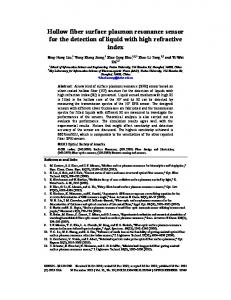
FIG. 1. Computer-aided design drawing of the microneedle array that was fabricated using the digital micromirror device-based stereolithography instrument.
= 15 mm兲. The cover slips and e-Shell 200 wafers were rinsed and sterilized in two 30 min rinses of 70% ethanol; the materials were subsequently rinsed in sterile de-ionized water. The e-Shell 200 wafers were placed in sterile Petri dishes in a laminar flow cabinet and sterilized with ultraviolet B light; both surfaces were exposed to ultraviolet B light. The materials were rotated 90° after a minimum of 2 h light exposure. Polymers were transferred to sterile 24-well culture plates, rinsed twice in sterile Hank’s balanced salt solution, and once in the appropriate cell culture medium. The e-Shell 200 wafers were placed in 2 ml of the appropriate cell culture medium and held in the incubator until seeded. Cryopreserved neonatal human epidermal keratinocytes and human dermal fibroblasts were obtained from a commercial source 共Lonza, Walkersville, MD兲. Fibroblast growth media 共FGM-2兲 and keratinocyte growth media 共KGM-2兲 were also obtained from a commercial source 共Lonza, Walkersville, MD兲. The human dermal fibroblasts and neonatal human epidermal keratinocytes were propagated in 75 cm2 flasks, grown to 75% confluency, and subsequently harvested. The cells were then seeded 共concentration= 40 000 cells per well兲 in a 24-well plate on e-Shell wafers 200 共n = 4兲, glass cover slips 共n = 4兲, and polystyrene well plates 共n = 4兲. Material rinsing and all media changes were performed by moving the test materials from one solution to the other using a forceps. The materials were placed in fresh medium after 48 h; this time point corresponded with 80% confluency for human dermal fibroblasts and neonatal human epidermal keratinocytes. MTT viability was assessed 24 h later. The materials with cells were rinsed using Hank’s balanced salt solution; desorption using isopropyl alcohol and agitation were subsequently performed. Isopropyl alcohol 共quantity= 100 l兲 was transferred to a new 96-well plate. Absorbance was determined 共 = 550 nm兲 with a Multiskan RC plate reader 共Labsystems, Inc., Franklin, MA兲. The mean values for percent viability were calculated. Significant differences 共p ⬍ 0.05兲 were determined using the PROC GLM Procedure 共SAS 9.1 for WINDOWS兲 共SAS Institute, Cary, NC兲. When significant differences were found, then multiple comparisons were performed using Tukey’s Studentized Range HSD 共Honestly Significant Difference兲 test at p ⬍ 0.05 level of significance. Arrays of hollow microneedles were fabricated from three-dimensional drawings that were created using Solidworks 共Dassault Systemes S.A., Velizy, France兲. Support structures were fabricated from three-dimensional drawings that were created using Magics RP 13 共Materialise NV, Leuven, Belgium兲. In the tetrahedron-shaped microneedle design, two faces of the microneedle exhibit a vertical orientation with respect to the substrate 共Fig. 1兲. The microneedle input dimen-
013415-6
Miller et al.
Biomicrofluidics 5, 013415 共2011兲
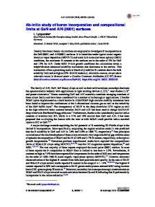
FIG. 2. Schematic showing steps used for assembly of the microneedle device.
sions included a triangular base with 1.2 mm sides, a height of 1.5 mm, and a vertical cylindrical channel 共diameter= 400 m兲. The needles were arranged into a 2 ⫻ 2 square array with 2 mm intermicroneedle spacing. The substrate input dimensions included lateral dimensions of 1 cm ⫻ 1 cm and a thickness of 500 m. Rapid prototyping of the microneedle array was performed using a Perfactory III SXGA⫹instrument 共EnvisionTEC GmbH, Gladbeck, Germany兲. A 150 W halogen bulb was used as the light source for polymerization of liquid e-Shell 200 resin. Selective polymerization of the resin in the X-Y plane was achieved using DMD optics 共Texas Instruments, Dallas, TX兲, specifically a DMD SXGA+ guidance chip with 1280⫻ 1024-pixel resolution. This instrument contains a build envelope of 90 mm⫻ 67.5 mm. After fabrication, the e-Shell 200 microneedle array was washed in isopropanol in order to remove the unpolymerized material. Postbuilding curing was accomplished using an Otoflash Post Curing System instrument 共EnvisionTEC GmbH, Gladbeck, Germany兲. This system contains two photoflash lamps and provides light exposure over a wavelength range of 300–700 nm. A Hitachi S-3200 共Hitachi, Tokyo, Japan兲 variable pressure scanning electron microscope with a Robinson backscattered electron detector was used for imaging the microneedle arrays. The microneedle arrays were coated with 60% gold-40% palladium using a Technics Hummer II instrument 共Anatech, Battle Creek, MI兲 prior to imaging. Skin penetration testing was performed with full-thickness cadaveric porcine skin since human skin and porcine skin exhibit similar structures. Trypan blue 共Mediatech, Inc., Manassas, VA兲, a toluidine-based dye, was used to assess the transdermal drug delivery functionality of the hollow microneedle arrays.24,43,58 Cadaveric full-thickness weanling Yorkshire/Landrace skin was stored at 3 ° C until testing was performed. Hollow microneedle arrays were inserted into full-thickness porcine skin. After removal of the arrays, trypan blue was applied to the insertion site; the site was subsequently washed with isopropanol swabs. The trypan blue-treated skin was subsequently imaged using optical microscopy. Images of a microneedle device before and after insertion into porcine skin were obtained using optical microscopy. The completed microneedle device was comprised of two layers 共Fig. 2兲. The upper layer consisted of the microneedle array; the lower layer provided support for the carbon fibers and facilitated the alignment of the carbon fibers to the microneedle array. The support component was fabricated from a 1.6 mm thick poly-共methylmethacrylate兲 共PMMA兲 piece. An array of holes was laser drilled through the PMMA piece using a Model PLS instrument, consisting of a 6.75 60 W CO2 laser and a computer-controlled XY stage 共Universal Laser Systems, Scottsdale, AZ兲 关Fig. 2共a兲兴. The holes were placed in a square pattern with 2 mm spacing. Using a Model HPDFO high
013415-7
Fiber electrodes within microneedles
Biomicrofluidics 5, 013415 共2011兲
FIG. 3. Optical images of 共a兲 an array of carbon fiber electrodes 共scale bar= 1 mm兲 and 共b兲 a single carbon fiber electrode 共scale bar= 100 m兲.
power density focusing optics lens 共Universal Laser Systems, Scottsdale, AZ兲, the diameter of the hole at the exit surface was measured at ⬃45 m. To control the carbon fiber length beyond the support surface, the support component was placed on top 共exit-side down兲 of a well with a depth of 100 m. Carbon fiber was manually inserted into each of the holes 共entrance side兲 and allowed to rest at the bottom of the well 关Fig. 2共b兲兴. The fibers were secured in place with acrylic adhesive on the entrance side after the desired well depth had been achieved 关Fig. 2共c兲兴. Figure 3 shows the optical images of an array of carbon fiber electrodes and a single carbon fiber electrode. The support layer and the microneedle layer were brought together in such a manner that the carbon fibers were positioned within the hollow shafts of the microneedles. The layers were subsequently adhered to each other. Metallic epoxy was applied to the back of the fibers in order to create the connection for the working electrode 关Fig. 2共d兲兴. 7 m carbon fibers 共Alfa Aesar, St. Louis, MO兲 were activated in a KOH solution 共concentration= 0.1 M兲 at a pH of 13 and at a potential of 1.3 V for 5 min. In situ diazotation of 2-amino-4-nitrophenol was performed by mixing a solution of 8 mM sodium nitrite and 6 mM 2-amino-4-nitrophenol on ice for 5 min to create the corresponding diazonium salt. After 5 min, the activated carbon fibers were inserted. Two cyclic voltammetry 共CV兲 scans were run from 0.4 to ⫺0.8 V at 0.1 V/s to enable the electrochemical grafting of the 2-nitrophenol and subsequent reduction to the aminophenol. The carbon fibers were modified with palladium to enable the detection of hydrogen peroxide. Activated carbon fiber bundles were placed in a solution of 1 mM palladium 共II兲 chloride; Pd was deposited by applying a potential of ⫺0.8 V for 120 s. All electrochemical measurements were obtained using a PGSTAT12 Autolab electrochemical instrument 共EcoChemie, Utrecht, The Netherlands兲. Data were acquired versus an Ag/AgCl reference and a Pt counterelectrode. III. RESULTS AND DISCUSSION
24 h MTT assay data for neonatal epidermal keratinocytes and human dermal fibroblasts are shown in Figs. 4共a兲 and 4共b兲, respectively. The test materials were noted to remain intact in the cell culture media over the course of the MTT assay. The e-Shell 200 and glass materials did not float in the wells; data for each material were fairly consistent. MTT viability of neonatal human keratinocytes was significantly higher for glass than for e-Shell 200 关Fig. 4共a兲兴. MTT viability for human dermal fibroblasts was significantly higher for glass than for e-Shell 200 关Fig. 4共b兲兴. Very slight differences in viability were noted; both neonatal epidermal keratinocytes and human dermal fibroblasts showed a slight decrease on e-Shell 200. Dissimilar responses by neonatal human epidermal keratinocytes and human dermal fibroblasts were attributed to the fact that epithelial
013415-8
Miller et al.
Biomicrofluidics 5, 013415 共2011兲
FIG. 4. MTT viability data for cells grown on e-Shell 200 acrylate-based polymer and glass cover slip. 共a兲 MTT viability of human epidermal keratinocytes grown on e-Shell 200 acrylate-based polymer compared to glass cover slip. A and B denote statistical differences 共p ⬍ 0.05兲 between the polymer and the control. 共b兲 MTT viability of human dermal fibroblasts grown on e-Shell 200 acrylate-based polymer compared to glass coverslip. A and B denote statistical differences 共p ⬍ 0.05兲 between the polymer and the control.
cells are derived from ectoderm; on the other hand, fibroblasts are derived from mesoderm.37 Consequently, these cell types have dissimilar cell receptors and responses to synthetic materials. It should be noted that e-Shell 200 only exhibited a slight but significant decrease in viability, which would not raise concerns regarding potential in vivo use in a transdermal medical device. The digital micromirror device-based stereolithography instrument allowed for the fabrication of approximately 200 arrays over a 3 h period. Figure 5 contains the scanning electron microscopy 共SEM兲 images of a hollow microneedle array and a single hollow microneedle prior to incorporation of carbon fiber electrodes. Measurements obtained from scanning electron micrographs showed that the microneedles exhibited heights of ⬃1030 m, triangular bases with side lengths of ⬃1120 m, and bore diameters of ⬃375 m. Good microneedle-to-microneedle uniformity was noted among the microneedles in the microneedle array. Differences between input and measured dimensions were attributed to translation of the computer-aided design drawing by the software. Digital micromirror device-based stereolithography and other rapid prototyping techniques involve tessellation, a conversion of the surface of the computer-aided design drawing into
013415-9
Fiber electrodes within microneedles
Biomicrofluidics 5, 013415 共2011兲
FIG. 5. Scanning electron microscopy image of hollow microneedles prior to incorporation of carbon fiber electrodes: 共a兲 plan view of hollow microneedle array and 共b兲 isometric view of single hollow microneedle.
a series of polygons. This polygon series is converted into a series of cross-sectional layers, which is subsequently used for layer-by-layer fabrication of the microneedle device. It is not possible to predict how the computer-aided design drawing is manipulated by the software. Microneedles undergo bending forces, compressive forces, shear forces, and skin resistance during skin insertion; the pressure necessary for human skin penetration exceeds 3.0⫻ 106 Pa.21 The skin penetration properties of the microneedle devices were evaluated using cadaveric porcine skin, which has been previously used as a model for assessing microneedle functionality.12,43 Figure 6共a兲 shows the porcine skin after application of the microneedle array, removal of the microneedle array, and application of trypan blue. The trypan blue spots indicate the penetration through the stratum corneum layer 共outermost layer兲 of the epidermis by the microneedle array and the localization of Typan Blue within the microneedle-generated pores. Figures 6共b兲 and 6共c兲 show optical micrographs of hollow microneedles before insertion into porcine skin and after insertion into porcine skin, respectively. These images indicate that the microneedles remain intact after skin insertion. The positioning of the carbon fiber electrodes within the microneedle device should 共a兲 facilitate interactions with the biological sample and 共b兲 minimize carbon fiber exposure to stresses associated with microneedle insertion into skin and movement at the microneedle device-skin interface. To facilitate interactions between the biological sample and the carbon fiber electrodes, the carbon fiber electrodes must be positioned at the centers of the microneedle bores. In addition, dead space between the carbon fiber electrodes and the microneedle sidewalls may allow for infiltration of the biological sample. Figure 7 contains the scanning electron microscopy images of a hollow microneedle array and a single hollow microneedle after incorporation of carbon fiber
FIG. 6. Images of microneedle array and cadaveric porcine skin after microneedle insertion. 共a兲 Optical micrograph showing delivery of trypan blue into microneedle-fabricated pores within cadaveric porcine skin 共scale bar 1 = mm兲. 共b兲 Optical micrograph showing hollow microneedles before insertion into cadaveric porcine skin. 共c兲 Optical micrograph showing hollow microneedles after insertion into cadaveric porcine skin.
013415-10
Miller et al.
Biomicrofluidics 5, 013415 共2011兲
FIG. 7. Scanning electron microscopy images of hollow microneedles after incorporation of carbon fiber electrodes: 共a兲 plan view of electrode-hollow microneedle array and 共b兲 isometric view of single electrode-hollow microneedle.
electrodes. Figure 7共b兲 shows a scanning electron microscopy image of a single hollow microneedle after incorporation of carbon fiber electrodes; this image reveals that the carbon fiber electrodes do not extend beyond the tip of the microneedle bore. Placement of carbon fibers within the microneedle bores necessitated a precise alignment of the microneedle bores and the carbon fibers 关Figs. 2共e兲 and 2共f兲兴; the positions of the laser-ablated holes in the lower layer of the microneedle device were coordinated with the positions of the microneedle bores in the upper layer of the microneedle device. The electrochemical response of the carbon fibers within the electrode-hollow microneedle device toward 5 mM Fe共CN兲63−/4− / 1 M KCl was evaluated. Figure 8 shows a cyclic voltammetric scan of 5 mM ferricyanide in 1 M KCl versus Ag/AgCl and Pt reference counterelectrodes, respectively, at a scan rate of 100 mV/s. Well defined oxidation/reduction waves were observed, indicating interaction between the carbon fiber electrodes and the test solution as a result of
FIG. 8. Cyclic voltammetric scan of 5 mM ferricyanide in 1 M KCl vs Ag/AgCl and Pt reference counterelectrodes, respectively, at a scan rate of 100 mV/s.
013415-11
Fiber electrodes within microneedles
Biomicrofluidics 5, 013415 共2011兲
FIG. 9. Cyclic voltammetric scans of 0, 50, 100, 300, and 500 M hydrogen peroxide 共pink, black, green, blue, and red curves兲 vs Ag/AgCl and Pt reference counterelectrodes, respectively, at a scan rate of 100 mV/s.
permeation of the microneedle bore by the test solution. The average formal potential 共E0⬘兲 for Fe共CN兲63−/4− was measured at 220 mV versus Ag/AgCl reference and platinum counterelectrodes, respectively. The average peak separation was ⌬Ep = 125 mV. These results indicate that the carbon fibers within the electrode-hollow microneedle device were capable of providing electrochemical measurements. Palladium-catalyzed oxidation of hydrogen peroxide on the carbon fibers within the electrodehollow microneedle devices was also investigated. Palladium was deposited onto the carbon fibers by applying a potential of ⫺0.8 V for 120 s in 1 mM Pd/0.5 M HCl prior to insertion into the microneedle device. Figure 9 contains cyclic voltammetric scans of 0, 50, 100, 300, and 500 M hydrogen peroxide, represented by pink, black, green, blue, and red curves, respectively, versus Ag/AgCl and Pt reference counterelectrodes, respectively, at a scan rate of 100 mV/s. This figure shows an increase in reductive currents after additions of 0, 50, 100, 300, and 500 M hydrogen peroxide, exhibiting a linear range of 100– 500 M and a detection limit of ⬃15 M 共based on the response of 50 M hydrogen peroxide; S / N = 3兲. Following the examples by Civit et al. and Nassef et al., the carbon fibers were modified with aminophenol 共o-AP兲 groups following in situ diazotination and electrografting of the corresponding diazonium salt.59,60 Modification of the carbon fiber electrode with o-AP has been shown to result in electrocatalytic oxidation of ascorbic acid and selective oxidation of ascorbic acid in the presence of common interferents such as uric and citric acids. Uric acid is a well-known interferent in electrochemical analysis of ascorbic acid, which is attributed to the fact that uric acid and ascorbic acid possess similar oxidation potential values.61 Linear sweep voltammograms of 100 mM phosphate buffer 共blank solution兲 and 1 mM ascorbic acid in 100 mM phosphate buffer 共pH = 7兲 versus Ag/AgCl and Pt reference counterelectrodes, respectively, at a scan rate of 100 mV/s are shown in Fig. 10. This result indicates that the carbon fibers within the electrode-hollow microneedle device are able to detect the ascorbate analyte with the low potential oxidation of ascorbic acid at 195 mV. IV. CONCLUSIONS
In summary, we have demonstrated that carbon fiber electrodes integrated within hollow microneedles, which were produced using digital micromirror device-based stereolithography, can
013415-12
Miller et al.
Biomicrofluidics 5, 013415 共2011兲
FIG. 10. Linear sweep voltammograms of 0 mM 共black兲 and 1 mM 共red兲 ascorbic acid in 100 mM phosphate buffer 共pH = 7兲 vs Ag/AgCl and Pt reference counterelectrodes, respectively, at a scan rate of 100 mV/s.
function as electrochemical transducers. The low cost and high yield offered by the digital micromirror device-based stereolithography process suggest that it is a suitable approach for large-scale production of hollow microneedles. The rapid processing rate offered by the digital micromirror device-based stereolithography process suggests that it is an appropriate approach for tailoring microneedle design. Studies involving porcine skin demonstrated that the microneedle arrays were able to penetrate the outermost layer of the skin and that the microneedles remained intact after insertion. The MTT assay indicated that the e-Shell 200 only exhibited a slight decrease in viability in a manner that would raise concerns regarding potential in vivo use in a nonimplantable medical device. Electrochemical measurements by the carbon fibers within the electrode-hollow microneedle device were demonstrated. In addition, chemical modification of the carbon fibers for selective analytes was shown; detection of hydrogen peroxide and ascorbic acid using these modified carbon fibers was demonstrated. While these experiments used outside reference and counterelectrodes, it is envisioned that selective microneedles within the microneedle arrays can be modified to integrate quasireference and counterelectrode components. It is also envisioned that a single microneedle array can include multiple functionalities, including drug delivery and monitoring of several analytes; such a device would be capable of integrated, closed-loop sensing and drug delivery. As mentioned by Wilson et al., biocompatibility issues must be successfully addressed in order achieve continuous in vivo monitoring.2 Decreasing the microneedle length is another important parameter that must be considered in future efforts; Gill et al. demonstrated that microneedle length was positively correlated with pain; patient pain may be reduced by decreasing microneedle length.13 Use of novel stereolithography-compatible materials, including materials based on vinyl esters, may provide higher cell viability rates.62 ACKNOWLEDGMENTS
Sandia is a multiprogram laboratory operated by Sandia Corporation, a Lockheed Martin Co., for the United States Department of Energy’s National Nuclear Security Administration under Contract No. DE-AC04-94AL85000. The authors acknowledge the support from Sandia National Laboratories’ Laboratory Directed Research and Development 共LDRD兲 program.
013415-13
Fiber electrodes within microneedles
Biomicrofluidics 5, 013415 共2011兲
C. I. L. Justino, T. A. Rocha-Santos, and A. C. Duarte, Trends Analyt. Chem. 29, 1172 共2010兲. G. S. Wilson and R. Gifford, Biosens. Bioelectron. 20, 2388 共2005兲. 3 A. Stett, U. Egert, E. Guenther, F. Hofmann, T. Meyer, W. Nisch, and H. Haemmerle, Anal. Bioanal. Chem. 377, 486 共2003兲. 4 J. Wang, P. V. A. Pamidi, and D. S. Park, Anal. Chem. 68, 2705 共1996兲. 5 J. Wang, Electroanalysis 13, 983 共2001兲. 6 J. D. Newman and A. P. F. Turner, Biosens. Bioelectron. 20, 2435 共2005兲. 7 J. J. Mastrototaro, Diabetes Technol. Ther. 2, 13 共2000兲. 8 S. Vaddiraju, I. Tomazos, D. J. Burgess, F. C. Jain, and F. Papadimitrakopoulos, Biosens. Bioelectron. 25, 1553 共2010兲. 9 S. Kaushik, A. H. Hord, D. D. Denson, D. V. McAllister, S. Smitra, M. G. Allen, and M. R. Prausnitz, Anesth. Analg. 共Baltimore兲 92, 502 共2001兲. 10 S. D. Gittard, A. Ovsianikov, B. N. Chichkov, A. Doraiswamy, and R. J. Narayan, Exp. Opin. Drug Deliv. 7, 513 共2010兲. 11 D. V. McAllister, P. M. Wang, S. P. Davis, J. H. Park, P. J. Canatella, M. G. Allen, and M. R. Prausnitz, Proc. Natl. Acad. Sci. U.S.A. 100, 13755 共2003兲. 12 J. H. Park, Y. K. Yoon, S. O. Choi, M. R. Prausnitz, and M. G. Allen, IEEE Trans. Biomed. Eng. 54, 903 共2007兲. 13 H. S. Gill, D. D. Denson, B. A. Burris, and M. R. Prausnitz, Clin. J. Pain 24, 585 共2008兲. 14 J. G. E. Gardeniers, J. W. Berenschot, M. J. de Boer, Y. Yeshurun, M. Hefetz, R. van ‘t Oever, and A. van den Berg, Proceedings of the IEEE Conference on MEMS, 2002, p. 141. 15 J. D. Zahn, D. Trebotich, and D. Liepmann, Biomed. Microdevices 7, 59 共2005兲. 16 H. Suzuki, T. Tokuda, and K. Kobayashi, Sens. Actuators B 83, 53 共2002兲. 17 S. Zimmermann, D. Fienbork, B. Stoeber, A. W. Flounders, and D. Liepmann, IEEE Proceedings of the 12th International Conference on Transducers, Solid-State Sensors, Actuators and Microsystems, 2003, p. 99. 18 E. V. Mukerjee, S. D. Collins, R. R. Isseroff, and R. L. Smith, Sens. Actuators, A 114, 267 共2004兲. 19 K. Tsuchiya, N. Nakanishi, Y. Uetsuji, and E. Nakamachi, Biomed. Microdevices 7, 347 共2005兲. 20 D. V. McAllister, M. G. Allen, and M. R. Prausnitz, Annu. Rev. Biomed. Eng. 2, 289 共2000兲. 21 S. Henry, D. V. McAllister, M. G. Allen, and M. R. Prausnitz, J. Pharm. Sci. 87, 922 共1998兲. 22 K. Chun, G. Hashiguchi, H. Toshiyoshi, and H. Fujita, Jpn. J. Appl. Phys., Part 2 38, L279 共1999兲. 23 K. Kim, D. S. Park, H. M. Lu, W. Che, K. Kim, J. B. Lee, and C. H. Ahn, J. Micromech. Microeng. 14, 597 共2004兲. 24 J. H. Park, M. G. Allen, and M. R. Prausnitz, J. Controlled Release 104, 51 共2005兲. 25 F. Pérennès, B. Marmiroli, M. Matteucci, M. Tormen, L. Vaccari, and E. D. Fabrizio, J. Micromech. Microeng. 16, 473 共2006兲. 26 P. M. Wang, M. Cornwell, J. Hill, and M. R. Prausnitz, J. Invest. Dermatol. 126, 1080 共2006兲. 27 A. Bertsch, P. Bernhard, C. Vogt, and P. Renaud, Rapid Prototyping J. 6, 259 共2000兲. 28 D. W. Hutmacher, M. Sittinger, and M. V. Risbud, Trends Biotechnol. 22, 354 共2004兲. 29 F. P. W. Melchels, J. Feijen, and D. W. Grijpma, Biomaterials 31, 6121 共2010兲. 30 L. A. Tse, P. J. Hesketh, D. W. Rosen, and J. L. Gole, Microsyst. Technol. 9, 319 共2003兲. 31 T. Matsuda and M. Mizutani, J. Biomed. Mater. Res. 62, 395 共2002兲. 32 X. Zhang, X. N. Jiang, and C. Sun, Sens. Actuators, A 77, 149 共1999兲. 33 J. W. Choi, I. B. Park, Y. M. Ha, M. G. Jung, S. D. Lee, and S. H. Lee, Proceedings of the SICE-ICASE 2006 International Joint Conference 共IEEE兲, 3678 共2006兲. 34 A. Ovsianikov, M. Malinauskas, S. Schlie, B. Chichkov, S. Gittard, R. Narayan, M. Löbler, K. Sternberg, K.-P. Schmitz, and A. Haverich, Acta Biomater. 7, 967 共2011兲. 35 A. Doraiswamy, C. Jin, R. J. Narayan, P. Mageswaran, P. Mente, R. Modi, R. Auyeung, D. B. Chrisey, A. Ovsianikov, and B. Chichkov, Acta Biomater. 2, 267 共2006兲. 36 A. Ovsianikov, B. Chichkov, P. Mente, N. A. Monteiro-Riviere, A. Doraiswamy, and R. J. Narayan, Int. J. Appl. Ceram. Technol. 4, 22 共2007兲. 37 S. D. Gittard, P. R. Miller, B. D. Boehm, A. Ovsianikov, B. N. Chichkov, J. Heiser, J. Gordon, N. A. Monteiro-Riviere, and R. J. Narayan, Faraday Discuss. 149, 171 共2011兲. 38 C. Sun, N. Fang, D. M. Wu, and X. Zhang, Sens. Actuators, A 121, 113 共2005兲. 39 S. D. Gittard, R. J. Narayan, J. Lusk, P. Morel, F. Stockmans, M. Ramsey, C. Laverde, J. Phillips, N. A. MonteiroRiviere, A. Ovsianikov, and B. N. Chichkov, Biotechnology 4, 129 共2009兲. 40 L. H. Han, G. Mapili, S. Chen, and K. Roy, J. Manuf. Sci. Eng. 130, 021005 共2008兲. 41 J. W. Choi, R. Wicker, S. H. Lee, K. H. Choi, C. S. Ha, and I. Chung, J. Mater. Process. Technol. 209, 5494 共2009兲. 42 J. W. Choi, E. MacDonald, and R. Wicker, Int. J. Adv. Manuf. Technol. 49, 543 共2010兲. 43 H. S. Gill and M. R. Prausnitz, J. Controlled Release 117, 227 共2007兲. 44 Technical Data: EnvisionTEC e-Shell 200 Series, http://www.envisiontec.de/fileadmin/pdf/matsheet_eshell200_en_s.pdf. Retrieved 27 January 2011. 45 S. D. Gittard, A. Ovsianikov, N. A. Monteiro-Riviere, J. Lusk, P. Morel, P. Minghetti, C. Lenardi, B. N. Chichkov, and R. J. Narayan, J. Diabetes Sci. Techmol. 3, 304 共2009兲. 46 R. Bader, E. Steinhauser, H. Rechl, W. Siebels, W. Mittelmeier, and R. Gradinger, Orthopade 32, 32 共2003兲. 47 D. Wolter, Aktuelle Probl Chir. Orthop. 26, 28 共1983兲. 48 R. Neugebauer, G. Helbing, D. Wolter, W. Mohr, and G. Gistinger, Biomaterials 2, 182 共1981兲. 49 D. G. Mendes, D. Angel, A. Grishkan, and J. Boss, J. Bone Joint Surg. Br. 67B, 645 共1985兲. 50 C. B. Jacobs, M. J. Peairs, and B. J. Venton, Anal. Chim. Acta 662, 105 共2010兲. 51 S. Chakraborty and C. R. Raj, J. Electroanal. Chem. 609, 155 共2007兲. 52 G. N. Babu, M. Bawari, V. N. Mathur, J. Kalita, and U. K. Misra, Clin. Chim. Acta 273, 195 共1998兲. 53 A. Grano and M. C. De Tullio, Med. Hypotheses 69, 953 共2007兲. 54 F. E. Harrison, M. E. Meredith, S. M. Dawes, J. L. Saskowski, and J. M. May, Brain Res. 1349, 143 共2010兲. 55 L. Salmenpera, Am. J. Clin. Nutr. 40, 1050 共1984兲. 56 A. J. Downard, A. D. Roddick, and A. M. Bond, Anal. Chim. Acta 317, 303 共1995兲. 57 T. Mosmann, J. Immunol. Methods 65, 55 共1983兲. 1 2
013415-14 58
Miller et al.
Biomicrofluidics 5, 013415 共2011兲
F. J. Verbaan, S. M. Bal, D. J. Van den Berg, W. H. H. Groenink, H. Verpoorten, R. Lüttge, and J. A. Bouwstra, J. Controlled Release 117, 238 共2007兲. 59 L. Civit, H. M. Nassef, A. Fragoso, and C. K. O’Sullivan, J. Agric. Food Chem. 56, 10452 共2008兲. 60 H. M. Nassef, A. E. Radi, and C. O’Sullivan, Anal. Chim. Acta 583, 182 共2007兲. 61 R. Bravo, C. Hsueh, A. Brajter-Toth, and A. Jaramillo, Analyst 共Cambridge, U.K.兲 123, 1625 共1998兲. 62 C. Heller, M. Schwentenwein, G. Russmueller, F. Varga, J. Stampfl, and R. Liska, J. Polym. Sci. A 47, 6941 共2009兲.