Integrated Online Localization and Navigation for People with Visual Impairments using Smart Phones Ilias Apostolopoulos, Navid Fallah, Eelke Folmer and Kostas E. Bekris Abstract— Indoor localization and navigation systems for individuals with visual impairments (VI) typically rely upon extensive augmentation of the physical space or heavy, expensive sensors; thus, few systems have been adopted. This work describes a system able to guide people with VI through buildings using inexpensive sensors, such as accelerometers, which are available in portable devices like smart phones. The method takes advantage of feedback from the human user, who confirms the presence of landmarks. The system calculates the user’s location in real time and uses it to provide audio instructions on how to reach the desired destination. Previous work suggested that the accuracy of the approach depended on the type of directions and the availability of an appropriate transition model for the user. A critical parameter for the transition model is the user’s step length. The current work investigates different schemes for automatically computing the user’s step length and reducing the dependency of the approach to the definition of an accurate transition model. Furthermore, the direction provision method is able to use the localization estimate and adapt to failed executions of paths by the users. Experiments are presented that evaluate the accuracy of the overall integrated system, which is executed online on a smart phone. Both people with visual impairments, as well as blindfolded sighted people, participated in the experiments. The experiments included paths along multiple floors, that required the use of stairs and elevators.
I. I NTRODUCTION Sighted people can navigate environments by primarily relying upon their visual senses to find their way. Individuals with visual impairments (VI) have to rely upon their compensatory senses (e.g., touch, hearing) for way-finding, resulting in reduced mobility. Unfamiliar environments are especially challenging as it is difficult to build a mental map of the surroundings using non-visual feedback [1]. To increase the mobility of individuals with VI, various navigation systems have been developed. There are many solutions for outdoor navigation systems [2], [3] which use GPS. Nevertheless, GPS signals cannot be received in indoor environments. Existing indoor navigation systems typically rely upon augmenting the physical infrastructure with identifiers such as RFID tags [4]–[6]. While RFID tags might be cheap, a large amount of them is required to cover a whole building. Although it is possible to install tags under carpets, hallways or large open spaces with concrete floor or tiles make such installation challenging and expensive. Other solutions employ laser sensors [7], [8] or cameras [9]. This work is supported by NSF CNS 0932423. Any opinions expressed in this paper are those of the authors and do not necessarily reflect the views of the sponsor. The authors are with the Department of Computer Science and Engineering, University of Nevada, Reno, 1664 N. Virginia St., MS 171, Reno, NV, 89557. Corresponding author:
[email protected].
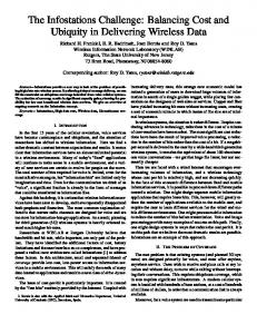
Fig. 1.
An individual with visual impairments testing the system.
A. System Overview and Challenges This paper describes an inexpensive solution that does not require physical infrastructure and depends on cheap, lightweight sensors, such as an accelerometer, already available on popular hand-held devices. The goal is a computationally light system that can operate on a smart phone. The approach utilizes interaction with the user through an audio/speech interface to provide directions using landmarks common to buildings and easily recognizable by people with VI, such as doors and hallway intersections. The user confirms landmarks through the smart phone interface allowing the system to track the user’s location by using sensor readings, a map, and the landmark confirmations. The proposed system does not focus on movable objects and local obstacle avoidance, which people with VI can already achieve with a cane. The proposed system has to deal with uncertainty at multiple levels, such as the user’s behavior, e.g., how quickly does the person move, how accurately one turns, and how good is one at identifying landmarks. For instance, users cannot easily distinguish a specific door, when there are multiple other doors close to it. The system has to consider the possibility the user confirmed an adjacent landmark of the same type. Furthermore, the sensors are erroneous, as portable devices usually carry low accuracy encoders. An additional complexity is that the system can only infrequently utilize landmark observations. This is in contrast to most robot localization solutions, where the system can frequently gather observations. Robot localization using smartphones corresponds to actively pursued work [10].
The approach described in this work considers the above sources of uncertainty and integrates localization and path planning primitives. Different variations of filtering algorithms are considered and evaluated in terms of their ability to simultaneously adapt to the step length of the user and provide accurate localization. To provide directions, a path is created from the start to the goal using the A* algorithm. Then, turn-to-turn directions are provided based on the location estimation of the user, provided by localization. Experiments show that this system is capable of successfully locating and guiding the user to the desired destination when a path with sufficiently identifiable landmarks is provided. B. Contribution The proposed approach and accompanying implementation are a significant extension of previous work by the authors [11]. The system is now executed online on a smartphone while previously the results were computed offline using precollected data. Due to a phone’s computational limitations, a new preprocessing step is introduced. This process analyzes the map and extracts data in order to avoid costly computations during online execution. The previous version of the system was using a fixed set of directions to evaluate different types of direction provision (e.g., frequent or infrequent use of landmark confirmations). The new implementation provides a dynamic direction provision, which makes use of infrequent confirmations of highly identifiable landmarks. It dynamically generates directions to the user based on the latest location estimation. The dynamic direction provision is able to correct the user’s path in case one doesn’t follow the instructions correctly. An important improvement is the introduction of the user’s step length as a state parameter in the filtering process so as to simultaneously estimate both the user’s location and step length. A variety of approaches to achieve this objective is described and evaluated. Furthermore, the final location estimation utilizes a k-means algorithm [12] to get a better estimation of the user’s location out of the particle filter. The k-means algorithm divides the particles in different clusters based on where they are concentrated and picks the cluster that corresponds to the highest probability. Significant changes have also been made in the experimental process. A new ground truth system is used in order to get a more accurate estimation of the user’s true location during the execution of the experiments. In particular, a vision-based system is used that detects landmarks installed on the ceiling. The accuracy of this ground truth procedure is approximately 2cm but costs more than an order of magnitude compared to the proposed method and requires carrying a heavy sensor. Additionally, extensive experiments are executed that involve multiple floors, as well as an increased number of landmarks that now include stairs, ramps and elevators. Finally, while in previous work the experiments involved only blindfolded people, this paper presents experiments with a number of people with visual impairments. The system is shown to work at least as good as it does with blindfolded people.
II. R ELATED W ORK Certain assistive devices focus on local hazard detection to provide obstacle-avoidance capabilities [13], [14]. Navigation systems, however, locate the user and provide directions to a user-specified destination. Many alternatives exist: A) Dead-Reckoning techniques integrate measurements of the human motion. Accelerometers [15] and radar measurements [16] have been used but without an external reference the error grows unbounded. B) Beacon-based approaches augment the physical space with identifiers, such as retro-reflective digital signs [9], infrared [3] or ultrasound identifiers [17], or RFID tags [4]– [6]. Nevertheless, locating identifiers may be hard, as beacons may require line of sight or close proximity. Wireless nodes suffer from multi-path effects or interference [18]– [20]. Another drawback is the significant time and cost spent installing and calibrating beacons. C) Sensor-based solutions employ sensors, such as cameras [21], that can detect pre-existing features, such as walls or doors. For instance, a multi-camera rig has been developed to estimate the 6 DOF pose of a person [22]. A different camera system matches physical objects with objects in a virtual representation of the space [23]. Nevertheless, cameras require good lighting conditions, and may impose a computational cost prohibitive for portable devices. An alternative makes use of a 2D laser scanner and achieves 3D pose estimation by integrating data from an IMU unit, a laser scanner, and the 3D structure of the space [7], [8]. While this setup has led to sophisticated algorithms and laser scanners can robustly detect low-level features, it depends on relatively expensive and heavy sensors. The proposed approach is also sensor-based. The user acts as a sensor together with light-weight, affordable devices, such as a pedometer, that are available on smart phones. It is interesting to study the feasibility of using such devices to interact effectively with a user with VI; and run localization primitives in real-time on a smartphone. Towards these objectives, this work utilizes probabilistic tools that have been shown effective in robotic localization. Bayesian methods work incrementally. They compute a new belief, given a previous one, a displacement measurement and sensor readings. One way to represent the belief is with a normal distribution as in the Extended Kalman filter (EKF) [24], [25]. While Kalman filters provide a compact representation and return the optimum estimate under linear Gaussian assumptions, they face problems when the true distribution is multi-modal. An alternative is to use particle filters [26]–[31], which sample estimates of the agent’s state. Particle filters can represent multi-modal distributions, which arise often in this work, at the expense of increased computation. This paper shows that it is possible to achieve sufficient accuracy and real-time performance with a particle filter. This project is also building upon multi-model state estimation work, which is used to calculate both the state and the model of the system, when the later is uncertain [32]–[35].
o(0:T ). A transition ut = (uft , uθt ) corresponds to a motion where the agent acquires the global orientation uθt and moves forward uft at time t giving rise to the following simplified model: (xt+1 , yt+1 , θt+1 ) = (xt +uft ·cos(uθt ), yt +uft ·sin(uθt ), uθt ) In this application the translation is measured by a pedometer and the orientation with a compass. An observation ojt of a landmark type Lj from state ξt = (xt , yt , θt ) implies: ∃ lj ∈ Lj : ||(xt , yt ), lj || < Robs
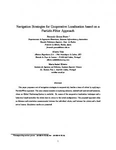
Fig. 2.
A communication graph between the components of the system.
III. A PPROACH A. High-level: Closed loop By incorporating the unique sensing capabilities of users with VI, the system aims to provide guidance in spaces for which the user does not have a prior cognitive map. The system assumes the availability of a 2D map with addressing information (room numbers), landmark locations, the user’s current location estimation and desired destination: 1. It then computes the shortest path to the destination using A* and translates the path into a set of directions that involve landmark confirmations. 2. The first direction is automatically provided to the user. The user presses a button on the phone after successfully executing each direction. 3. Directions are provided iteratively upon the confirmation of each landmark, or when the user is considered not to be following the appropriate path. Figure 2 lists a high-level overview of the four different components of the system: (1) the cyber-representation component stores annotated models of indoor environments; (2) the localization component provides a location estimate of the user with VI; (3) the direction provision component provides directions to a user specified location; and (4) the audio/speech interface component interacts with the user. The focus in this paper is on localization and direction provision. The landmarks used are features such as doors, hallway intersections, floor transitions, water coolers, ramps, stairs and elevators. Such landmarks play an important role in the cognitive mapping of indoor spaces by users with VI and are easily recognizable by touch and sound, thus limiting the need for additional physical infrastructure [36], [37]. B. Localization Consider a planar system (human with VI) moving among n static landmarks (tactile features of indoor spaces). Let ξ = (x, y, θ) denote the state of the system. A grid map m specifies whether each point (x, y) is occupied by an obstacle or not. The map also stores the n landmarks present in the world. The landmarks belong to k different types {L1 , . . . , Lk }, such as doors, hallway intersections or floor transitions (typically k < n). The data dT = (o(0:T ), u(0:T −1)) available to the system up to time T are transitions u(0:T − 1) and observations
i.e., a user can sense a landmark type Lj if such a landmark is within a predefined observation distance Robs . The objective is to be able to incrementally estimate the user’s state ξT at time T , for which the general Bayes filter provides a solution: Z BT = η · P (oT |ξT , m) P (ξT |uT −1 , ξT −1 ) · BT −1 · dξT −1 where P (ξT |uT −1 , ξT −1 ) is the transition model, P (oT |ξT , m) is the observation model and η is a normalization factor. Integrating over all states renders the explicit computation of the above equation inefficient. Most online algorithms simplify the problem by approximating the previous equation. This work follows a Particle Filter approximation. a) Particle Filter: BT can be represented through a set of P particles pi = (ξ i , wi ) (i ∈ [1, N ]). Each particle stores a state estimate ξ i and a weight wi , representing the probability of ξ i being the true state. As the number of particles increases, the particle filter converges to the belief distribution. This work follows an importance sampling approach for updating the particle filter [26]. b) Transition Model: Raw data become available from the accelerometer, which are then filtered to detect when the user has made a step. The approach collects all the pedometer readings that have been produced during the last time step, which typically correspond to zero or one steps. This value has to be translated into a distance estimate. Because the compass is highly erroneous, the system does not use its raw readings. Instead it splits them into 8 discrete orientations at 0 degrees, 45 degrees, 90 degrees, 135 degrees, etc. c) Observation Model: If the particle estimate crosses a wall, then the weight of a particle is zero. If there is a landmark confirmation of type Lj , then the approach searches for the closest landmark of this type and prunes all the particles not in the vicinity of such a landmark. Particles that detect the landmark on the wrong side of the wall based on the particle’s estimated orientation get a zero weight. d) Sampling: Particles with zero weight get replaced with particles that have higher weight. If all particles die, they get reset to the vicinity of the closest landmark of the type confirmed. If all particles die without a landmark confirmation, the particles backtrack to their previous state. e) Location Estimation: After the sampling process, a k-means algorithm is used to estimate the user’s current location [12]. The k-means algorithm classifies the particles into clusters. The number of clusters changes dynamically.
The method is initialized with three clusters. Then the algorithm checks the pairwise distances of cluster centers. If the centers of two clusters are closer than a threshold, the two merge into one. If a cluster’s radius gets bigger than a given threshold then the cluster splits into two. Thus, if the particles are concentrated in one place, only one cluster can be used while if they are dispersed throughout the environment more are used. After clustering, the algorithm selects the cluster with the highest accumulated weight and returns its center as a location estimate.
C. Adapting to Different Step Lengths It is highly desirable for the localization process to be able to simultaneously localize the user and estimate one’s step length. This is important since the step length might be different from user to user, from path to path, or even within the same path. To accomplish this objective, three variations of particle filtering were implemented: A. A benchmark particle filter where the standard deviation for the noise in the step length estimate is significantly increased. The standard deviation was large enough so as to include all possible step lengths for different users. B. A particle filter which includes a step length estimate as part of a particle’s state. The particles are initialized so that they cover all possible step lengths for different users. Each particle advances based on the local estimate it keeps for the user’s step length. The step length estimation is updated using a very small deviation value so as to allow the approach to detect small changes in the user’s step length during the execution of a path. After a landmark confirmation, only the particles that estimate that the user is in the vicinity of such a landmark based on a more accurate estimation of the user’s step length, will survive. C. A technique that utilizes 10 particle filters, where the total number of particles is equal to the approaches above. Each filter has a different mean estimate for the step length and the standard deviation is somewhere in between the above two methods. The particles in each filter advance based on the step length estimation of the individual filter. After landmark confirmations, the filters with the correct step length estimation survive while the rest get replaced with a variation of the filters that survived. The objective of the last two alternatives is to adapt the location estimate to the user’s step length. In particular for the third method, during the sampling process, the filter with the highest weight is calculated. This is achieved by summing the weights of all particles in each filter and choosing the one with the maximum accumulated weight. Within each filter, the particles with the higher weights are the ones sampled. In case that all particles in a filter die, the whole filter copies the position estimates from the filter with the highest weight. It also copies the mean of the step length distribution and alters it slightly given a small standard deviation. The exact parameters used for the experiments in this paper are provided in the experimental section.
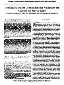
Fig. 3. Example of a tile storing information about the closest doors and hallway intersections.
D. Preprocessing Step Because of the limited processing power of portable devices, some computationally expensive operations have been moved to an offline process, which creates maps and integrates additional data to provide them during the online execution of the system. The maps can be easily created by a sighted user without the need for additional sensors. During the offline process, the following 3 steps are executed: 1. Given the map M and some accessible points {a1 , . . . , an }, the offline process finds the set of accessible spaces A = {A1 , . . . , Am } on the map using an eight neighbor flooding algorithm. The set A typically represents hallways and spaces where the user can navigate through. In the experiments for this paper, only corridors were considered. A is represented as a bitmap with ones for accessible points and zeros for inaccessible ones. 2. The accessibility map M A is used to create a set of prestored positions pi (li ) in the vicinity of each landmark li in the accessible space (i.e., within a landmark’s observation range). The positions are randomly sampled around each landmark li and assigned to this landmark in the map data structure M . 3. A lower resolution map m of M A is created by dividing M A into non-overlapping tiles mpq . Each mpq has a size of 1m2 . Only tiles mpq that overlap with accessible areas are maintained. Each accessible tile mpq holds information for all types of landmarks {L1 , . . . , Lk } close to it (Fig. 3). Up to five landmarks in the vicinity of a tile (8m radius) for each landmark type Lj are stored for each mpq . Weights W = {w1 , . . . , wi } inversely proportional to the distance of landmark li to the center of mpq are also stored for each landmark. When all accessible tiles mpq are created, they are stored in the map M . The offline data are used during the online process when all particles die after a landmark confirmation. In this case, it is necessary to reset the particles in the vicinity of landmarks of the type Lj that was confirmed. When a particle Pi needs to be resampled close to a landmark of type Lj , the system finds the tile mpq in m that Pi was previously located and retrieves the list of landmarks with type Lj assigned to mpq .
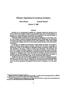
Fig. 4.
The map of the first (left) and second (right) floor of the building where the experiments took place.
A landmark lj from the list is randomly selected with a probability proportional to the weights W , which represents the probability that the user might actually be close to any of these landmarks instead of the particle’s location. The particle location is replaced randomly by one of the positions (from step 2 above) in the vicinity of lj . By storing the specified offline information, the online process avoids searching for accessible spaces to reset the states of the landmarks as this might become computationally expensive. The proposed offline process may be heavy for a smart phone but it can be executed on a desktop computer, where it takes less than a second. E. Direction Provision The A* algorithm is used for path planning. The path can be optimized based on a criterion such as shortest path, as done in this work. Alternative objectives can also be considered for the path. In particular, the path should be easy to follow by a person with VI, it should reduce localization uncertainty, and ensure the user’s safety. The number and frequency of landmarks for which commands are provided can affect the performance and usability of the system. Requiring the user to confirm all the landmarks along a path may seem the best approach for accurate localization but previous work has shown that the uncertainty can be reduced by using infrequent confirmations of distinctive and unique landmarks, such as hallway intersections [11]. Furthermore, planning a path that guides the user along walls and avoids open areas will help the user to maintain their orientation and lower uncertainty. To ensure safety, the path avoids obstacles or hazardous areas such as ramps with no handrails. The landmarks specified in the directions must be safe to touch as the user will confirm their existence using a cane or a hand. In case the user did not follow the instructions correctly and walks away from the prespecified path, the system can detect it and issue new instructions. The system calculates the location estimate after every step and checks the distance from the path. If the distance is higher than 2 meters then the system informs the user, calculates a new path based on the latest location estimate and provides to the user a new set of instructions.
IV. E XPERIMENTS A. Setup The system was implemented in Java for the Android mobile platform. Maps of the 1st and 2nd floors of the engineering building of the University of Nevada, Reno were created (Figure 4). The maps include: (i) 211 doors, (ii) 15 hallway intersections, (iii) 6 water coolers, (iv) 1 floor transition, (v) 2 elevators, (vi) 8 sets of stairs and (vii) 1 ramp. For the experiments, 10 paths were tested from which 2 included multiple floors. The application provided the instructions through a text to speech synthesis library embedded on the Android platform. The user could confirm the landmarks by pressing anywhere on the screen. Thirteen volunteers participated in the experiments. Five of them were people with VI while the rest were sighted people who were blindfolded. Some of the participants had visited the building before, while others had not. All users were provided with a white cane and the phone. Before the experiments, the blindfolded users were trained in the use of a cane. A commercial localization system called Hagisonic StarGazer was used to capture the ground truth. The product is consisting of (1) a set of passive landmarks with unique IDs mounted on the ceiling; (2) an infrared camera that outputs ID, distance, and angle of the closest landmark; and (3) an open source software library. To use the system for human tracking, the camera and a battery are installed on a belt that the user wears during experiments. The user carries a tablet (Fig. 5) that records the landmark information received from the camera and calculates the user location based on the relative landmark location. The accuracy of the camera is 2cm when installed on a flat surface; but the camera is sensitive to tilt and might result in incorrect readings when in- Fig. 5. A sighted user, running exstalled on a belt. To re- periments blindfolded wearing the duce the noise the ground ground truth equipment truth is smoothed using an outlier detection algorithm.
As mentioned in Section III-C, there were three approaches evaluated for their ability to adapt to the user’s step length. The first has one filter that updates the position estimates given a Gaussian distribution for the step length with a mean of 0.54 meters and a standard deviation of 0.08 meters. The second system has one filter where the step length is stored together with the state estimate. Initially, the particles’ internal estimate of the step length is distributed according to the same probability distribution as in the first approach. Each particle advances based on the local value it stores for the step length. In every step the step length changes in order to be able to detect small changes in the step length of the user. A Gaussian distribution is used with a 0m mean and st. dev. of 0.007 meters. The third alternative uses 10 filters. The step length mean value starts at 0.37 meters for the first particle filter and increases by 0.06 meters for each consecutive filter. The standard deviation of these distributions is 0.02 meters. B. Localization Accuracy Table I provides the average distance between the ground truth and the localization estimate when the path is completed. The system works as well, if not better, for users with VI compared to blindfolded users. For users with VI, there is an additional path, which is an alternative route from 242A to 231A. The original path was failing most of the times because it required counting 6 doors to reach the desired destination without a landmark confirmation in between. In order to deal with this issue an alternative path was also tested as shown in Figure 6. Although this path is longer, it has higher probability of leading the user to the desired destination. This is confirmed also from the error values extracted from the experiments on this alternative path. This motivates a path planning process which calculates alternatives that don’t belong in the same homotopic class and take into consideration the probability of each path to lead the user to the desired destination based on the quality of the landmarks. Fig. 7 shows the localization error during the progression of a path. In this figure one can notice that, for some particle filters the localization error increases during the execution of the path while for the ones that have a step length that is close to the actual step length of the user the error remains Distance from Ground Truth Path 109-118 Path 118-129 Path 129-109 Path 206-260 Path 231A-208 Path 242A-231A Path 251-240A Path 260-131 Path 260-251 Path J1-206 Path 242A-231A(Alt)
Blindfolded Users Mean STDEV 1.31 0.48 4.25 8.27 2.61 1.53 1.11 0.38 1.23 0.78 13.95 7.95 1.29 0.33 4.05 3.04 1.18 0.23 2.16 1.09 -
Users with VI Mean STDEV 1.23 2.17 1 0.68 1.86 1.49 2.73 2.37 1.37 1.52 12.81 5.1 0.49 0.66 2.73 1.76 0.81 1.06 1.44 1.72 0.56 0.57
Two different paths that lead to the same goal. The alternative has a higher success probability. Fig. 6.
low. After the first confirmation of a landmark, though, the particle filters that have an incorrect step length estimation are replaced with the ones that have a better estimation and the error decreases. However, one landmark confirmation is not always enough to estimate an accurate value of the user’s step length. That is why after the first landmark confirmation, the error starts growing again for some particle filters. However, after the second confirmation, the particles converge to similar step lengths. When the user reached the goal all the values were close to 0.5-0.6 meters step length. C. Adaptation to the User’s Step Length The three different particle filters described in Section III-C were tested in order to conclude which one is more suitable for adapting to the user’s step length. Table II holds the mean localization error and standard deviation for the three different methods. In each case, six experiments were executed by three different participants. The two methods that do aim to estimate the user’s step length perform better than the straightforward particle filter with large standard deviation. Overall the approach that utilizes multiple particle filters calculates a better estimation of the user’s step length. D. Computational overhead Table III holds performance data obtained from profiling. The system managed to run all the experiments smoothly without running into issues due to the limited computational power of the phone. To avoid delays in the computations, we used a relatively small number of particles (1,000). E. Direction Provision Table IV shows the average distance of the ground truth (i.e., the true location of the user) from the desired destination. The majority of the paths were completed successfully. In particular, in 76% of the experiments the system guided the user to the desired destination within an average distance of 1.5 meters. In 11% of the experiments the system guided the user to a location adjacent to the desired destination with an average distance of 2.75 meters. Distance from Destination Method 1 Method 2 Method 3
Mean 2.31 1.02 0.02
STDEV 2.30 1.12 0.05
TABLE I
TABLE II
G ROUND TRUTH VS LOCALIZATION ESTIMATE UPON COMPLETION ( M ).
L OCALIZATION VS GROUND TRUTH FOR THE ADAPTIVE METHODS ( M )
Profiling
Average total time Average time per step Time st. dev. Max step time Average steps Average time for transition Average time for observation Average time for sampling
Path 109118 2808.13 39.14 22.11 95.13 71.63 1281.75 2048.13 39.88
Path 118129 4332.13 37.72 21.47 99.75 114.75 1970.88 3116.75 58.25
Path 129109 5237.13 39.88 23.03 106.25 131.5 2220.38 3764.75 64
Path 206260 3444.13 39.23 23.40 104.88 87.88 1556.75 3764.75 35.25
Path 231A208 3114.75 40.01 22.29 106.38 77.25 1409.38 2241.63 44.38
Path 242A231A 4387.88 39.41 23.152 114.13 111.375 2007.5 3158.5 40.5
Path 251240A 3397.88 39.02 22.04 99.5 86.38 1490.25 2358.38 43.25
Path 260131 4861.86 41.25 24.16 118 117.86 2118.57 3549.57 69.714
Path 260251 3953.5 40.39 23.24 105.13 97.13 1811.75 2883.75 46.88
Path J1206 3684.38 38.69 21.79 92.5 95.5 1676.13 2629 39.13
TABLE III P ROFILING DATA ( MSEC ) Distance from Destination Path 109-118 Path 118-129 Path 129-109 Path 206-260 Path 231A-208 Path 242A-231A Path 251-240A Path 260-131 Path 260-251 Path J1-206
Mean 1.17 3.47 1.78 1.15 0.83 4.08 0.51 2.05 0.74 1.21
STDEV 0.5 5.39 0.95 0.35 0.24 2.92 0.25 2.34 0.32 0.77
TABLE IV D ISTANCE BETWEEN GROUND TRUTH AND DESTINATION ( M )
Fig. 7.
A graph showing the localization error during a path.
Users might fail to follow the instructions correctly. In this case the system adapts the instructions depending on what the location estimation of the user is. For example, in a path the user had to follow these instructions: (a) “Follow the wall to your left until you reach an intersection”, (b) “Turn left” and (c) “Follow the wall to your right until you reach the second door to the right” (last part of the path in Figure 8). The user, however, advanced beyond the intersection without turning left. In this case the phone provided the following: (a) “Follow the wall to your left until you reach an intersection”, (b) “Off course. Recalculating path. Turn around”, (c) “Follow the wall to your right until you reach an intersection”, (d) “Turn right” and (e) “Follow the wall to your right until you reach the second door to the right”. This example shows how the phone can detect the event a user has advanced beyond a landmark confirmation location and that the method can adapt to such failures.
V. D ISCUSSION This paper presented an indoor navigation system for people with VI that uses a minimalistic and interactive sensing approach achievable with a smart phone. The sensors used in the experiments are inexpensive and widely available but they are also highly erroneous. For instance, compass sensors perform very poorly indoors due to metal structures and electro-magnetic noise. This was also the case in the building where the experiments of this paper were executed. Despite this challenge, it was still possible to track multiple human users, who did not have any visual feedback, with sufficient accuracy through an interactive process. The impressions of the users were positive. All users found that the directions were easy to follow and that the system navigated them efficiently. They also agreed this system could minimize the chance that they would get lost in unfamiliar environments. Suggestions for improvement included: (1) improving the accuracy; (2) being able to repeat directions and (3) not holding the phone in the hand but in a pocket. This line of research opens the door to exciting new applications for methods from robotics in the area of humancentered autonomous intelligent systems. It is interesting to study how to plan alternative paths that lead along a larger number of distinguishable landmarks, so as to further increase the probability the user arrives at the destination and the localization estimate is more accurate. Furthermore, it would be interesting to investigate more robust methods for automatically detecting significant changes in the user’s
Fig. 8.
Example of path correction.
step length during a path. Similarly, it is possible to make use of more realistic models of human motion [38] instead of the unicycle-like system employed in this work. Additionally, there is connection to human-robot research which could help address cases were there are incorrect observations. 2D maps of indoor environments can be acquired from architectural blueprints. Nevertheless, it may be useful to use richer representations. 3D virtual models can be employed to represent indoor environments with multiple levels and features like low ceilings, ramps, uneven floors, and rails, which are impediments to navigation for users with VI. It is interesting to investigate how to extract landmarks, such as doors or staircases, automatically from the geometry of such models in order to utilize them in navigation and localization tools for individuals with VI. Crowdsourcing tools could be used so that 3D models of popular environments can be dynamically updated when they change so as to support tools such as the one described here. Still the focus of this work is on high-level navigation and not on local obstacle avoidance, which people with VI can already achieve with a cane. R EFERENCES [1] O. Lahav and D. Mioduser, “Multisensory virtual environment for supporting blind persons’ acquisition of spatial cognitive mapping – a case study,” in World Conference on Educational Multimedia, Hypermedia and Telecommunications, 2001, pp. 1046–1051. [2] J. M. Loomis, R. G. Golledge, and R. L. Klatzky, “Navigation system for the blind: Auditory display modes and guidance,” Presence: Teleoper. Virtual Environ., vol. 7, no. 2, pp. 193–203, 1998. [3] D. A. Ross and B. B. Blasch, “Development of a wearable computer orientation system,” Personal Ubiquitous Comput., vol. 6, no. 1, pp. 49–63, 2002. [4] V. Kulyukin, C. Gharpure, J. Nicholson, and S. Pavithran, “Rfid in robot-assisted indoor navigation for the visually impaired,” in Proc. of the IEEE/RSJ Int. Conf. on Intelligent Robots and Systems, Sendai, Japan, Sept. 28-Oct.2 2004, pp. 1979–1984. [5] M. Bessho, S. Kobayashi, N. Koshizuka, and K. Sakamura, “Assisting mobility of the disabled using space-identifying ubiquitous infrastructure,” in 10th Int. ACM Conf. on Computers and Accessibility (ASSETS). Halifax, Canada: ACM, 2008, pp. 283–284. [6] T. Amemiya, J. Yamashita, K. Hirota, and M. Hirose, “Virtual leading blocks for the deaf-blind: A real-time way-finder by verbal-nonverbal hybrid interface and high-density rfid tag space,” in Proc. of the IEEE Virtual Reality, Washington, DC, USA, 2004. [7] J. A. Hesch and S. I. Roumeliotis, “An indoor localization aid for the visually impaired,” in IEEE International Conference on Robotics and Automation (ICRA), Roma, Italy, April 10-14 2007, pp. 3545–3551. [8] J. A. Hesch, F. M. Mirzaei, G. L. Mariottini, and S. I. Roumeliotis, “A 3D Pose Estimator for the Visually Impaired,” in IEEE/RSJ Intern. Conf. on Intel. Robots and Systems (IROS), Oct. 2009, pp. 2716–2723. [9] B. Tjan, P. Beckmann, N. Giudice, and G. Legge, “Digital sign system for indoor wayfinding for the visually impaired,” in IEEE CVPR: Workshop on Computer Vision Applications for the Visually Impaired, San Diego, CA, June 20-25 2005. [10] N. Kothari, B. Kannan, and M. B. Dias, “Robust indoor localization on a commercial smart-phone,” The Robotics Institute, Carnegie-Mellon University, Tech. Rep., 2011. [11] E. Apostolopoulos, N. Fallah, E. Folmer, and K. E. Bekris, “Feasibility of interactive localization and navigation of people with visual impairments,” in 11th IEEE Intelligent Autonomous Systems (IAS-10), Ottawa, CA, August 2010 2010. [12] J. A. Hardigan, “Clustering algorithms,” 1975. [13] S. Shoval, J. Borenstein, and Y. Koren, “Auditory guidance with the navbelt - a computerized travel aid for the blind,” IEEE Trans. on Systems, Man and Cybernetics, vol. 28(3), pp. 459–467, Aug. 1998. [14] D. Yuan and R. Manduchi, “Dynamic environment exploration using a virtual white cane,” in IEEE Conf. on Computer Vision and Pattern Recognition, San Diego, CA, June 20-25 2005, pp. 243–249.
[15] F. Cavallo, A. M. Sabatini, and V. Genovese, “A step towards gps/ins personal navigation systems: real-time assissment of gait by foot inertial sensing,” in IEEE/RSJ Int. Conf. on Intelligent Robots and Systems, Edmonton, Canada, August 2-6 2005, pp. 1187–1191. [16] P. Van Dorp and C. A. Groen, F., “Human walking estimation with radar,” IEE Proceedings, Radar, Sonar and Navigation, vol. 150, no. 5, pp. 356–365, 2003. [17] L. Ran, S. Helal, and S. Moore, “Drishti: An integrated indoor/outdoor blind navigation system and service,” IEEE International Conference on Pervasive Computing and Communications, p. 23, 2004. [18] T. H. Riehle, P. Lichter, and N. A. Giudice, “An indoor navigation system to support the visually impaired,” in 30th Annual International Conference of the IEEE Conference on Engineering in Medicine and Biology Society (EMBS), Aug. 2008, pp. 4435–4438. [19] A. M. Ladd, K. E. Bekris, A. Rudys, G. Marceau, L. E. Kavraki, and D. S. Wallach, “Robotics-based location sensing using wireless ethernet,” in Eight ACM International Conference on Mobile Computing and Networking (MOBICOM 2002), ACM Press. Atlanta, GA: ACM Press, September 2002. [20] A. M. Ladd, K. E. Bekris, A. Rudys, L. E. Kavraki, and D. S. Wallach, “On the feasibility of using wireless ethernet for indoor localization,” IEEE Transactions on Robotics and Automation, vol. 20, no. 3, pp. 555–559, June 2004. [21] O. Koch and S. Teller, “Wide-area egomotion estimation from known 3d structure,” in Proc. of the IEEE Conf. on Computer Vision and Pattern Recognition, Minneapolis, MN, June 17-22 2007, pp. 1–8. [22] F. Dellaert and S. Tariq, “A multi-camera pose tracker for assisting the visually impaired,” in 1st IEEE Workshop on Computer Vision Applications for the Visually Impaired, June 20-25 2005. [23] A. Hub, J. Diepstraten, and T. Ertl, “Design and development of an indoor navigation and object identification system for the blind,” in 6th Int. ACM SIGACCESS Conf. on Computers and Accessibility (ASSETS). Atlanta, GA, USA: ACM, 2004, pp. 147–152. [24] R. E. Kalman, “A new approach to linear filtering and prediction problems,” Transactions of the ASME-Journal of Basic Engineering, vol. 82, no. 35-45, 1960. [25] R. Smith, M. Self, and P. Cheeseman, Estimating Uncertain Spatial Relationships in Robotics. Springer Verlag, 1990. [26] N. J. Gordon, D. J. Salmond, and A. F. M. Smithm, “Novel approach to nonlinear/non-gaussian bayesian state estimation,” IEE Proceedings on Radar and Signal Processing, vol. 140, no. 2, pp. 107–113, 1993. [27] S. Thrun, D. Fox, W. Burgard, and F. Dellaert, “Robust monte carlo localization for mobile robots,” Artificial Intelligence, vol. 128, no. 1-2, pp. 99–141, 2000. [28] S. Lenser and M. Veloso, “Sensor resetting localization for poorly modelled mobile robots,” in Proc. of the IEEE Int. Conf. on Robotics and Automtion (ICRA), San Francisco, April 2000. [29] I. M. Rekleitis, “A particle filter tutorial for mobile robot localization,” Centre for Intelligent Machines, McGill Univrsity, Montreal, Quebec, Canada, Tech. Rep. TR-CIM-04-02, 2002. [30] S. M. Oh, S. Tariq, B. Walker, and F. Dellaert, “Map-based priors for localization,” in IEEE/RSJ International Conference on Intelligent Robots and Systems (IROS), 2004. [31] S. Thrun, W. Burgard, and D. Fox, Probabilistic Robotics. MIT Press, September 2005. [32] Stochastic Models, Estimation and Control, ser. Mathematics in Science and Engineering. Maybeck, P. S., 1982, vol. 2. [33] E. Mazor, A. Averbuch, Y. Bar-Shalom, and J. Dayan, “Interacting multiple model methods in target tracking: A survey,” IEEE Trans. on Aerospace and Electronic Systems, vol. 34, pp. 103–123, 1998. [34] X. R. Li, X. Zhi, and Y. Zhang, “Multiple-model estimation with variable structure, part iii: model-group switching algorithm,” in IEEE Trans. Aerosp. Electron. Syst.,, vol. 35, no. 1, 1999, pp. 225–241. [35] S. Skaff, A. Rizzi, H. Choset, and M. Tesch, “Context identification for efficient multiple-model state estimation of systems with cyclical intermittent dynamics,” IEEE Transactions on Robotics, vol. 27, no. 1, February 2011. [36] A. A. Kalia, G. E. Legge, and N. A. Giudice, “Learning building layouts with non-geometric visual information: the effects of visual impairment and age,” Perception, vol. 37, no. 11, pp. 1677–99, 2008. [37] A. P. B Tsuji, G Lindgaard, “Landmarks for Navigators who are Visually Impaired,” in Proc. Intern. Cartography Conference, 2005. [38] G. Arechavaleta, J.-P. Laumond, H. Hicheur, and A. Berthoz, “An optimality principle governing human walking,” in IEEE Transactions on Robotics, vol. 24, no. 1, 2008.