Such creative development tasks â such as user interface design or design of ... or animation workbenches like Adobe Flash, or even 3D graphics tools like 3D.
Integrating Heterogeneous Tools into Model-Centric Development of Interactive Applications Andreas Pleuss, Arnd Vitzthum, Heinrich Hussmann Department of Computer Science, University of Munich Munich, Germany {pleuss, vitzthum, hussmann}@cip.ifi.lmu.de http://www.medien.ifi.lmu.de
Abstract. The development of successful interactive applications often requires high efforts in creative design tasks to build high quality user interfaces. Such creative development tasks – such as user interface design or design of specific features like 3D objects – are usually performed using different tools optimized for the respective task. For example, in early development stages, tools like Photoshop or Flash are established for creating user interface prototypes. 3D graphics is usually developed using 3D authoring tools. In this paper we propose a general approach to integrate heterogeneous tools into model-centric development. Thereby, the models act as central hub between different specific tools and development steps. This enables excellent support for creative design while using concepts from model driven engineering, such as explicit metamodels and transformations, to facilitate a well-coordinated development and ensure consistency of the resulting overall application. We illustrate this approach by concrete examples from different application domains.
1
Introduction
From an engineering point of view, the approach of model-driven development is very appropriate for the production of high-quality software. However, a key problem in using the state-of-the-art modelling languages (like UML), is that the audience which can understand the models is severely restricted to people being trained in using high abstraction levels. This in practice mostly means engineers or scientists, may they be part of the development team or work on the customer side. It is already difficult for domain specialists without computer science background to deal with abstract models, and for most end users it is completely impossible. This observation is in unpleasant contrast to the fact that the end users are the target group for which the whole design effort is directed. The overall acceptance of software systems by its end users is often determined by properties of its user interface [1, 2], so it makes good sense to adopt a user-centred design process. Such a process typically uses very early prototypes and interface mock-ups to obtain feedback from end users. These
2
Andreas Pleuss, Arnd Vitzthum, Heinrich Hussmann
steps produce artefacts which are of a completely different nature compared to the abstract (e.g. UML-based) engineering models. Moreover, there is a rapidly growing species of applications where the key features are located rather in the user interface than in the background logic. Examples are all kinds of product presentations on the Web or multimedia applications in entertainment sector. These applications cannot be developed without taking care of the user interface and its graphical design from the beginning. So it can be stated that development projects face a clash of cultures between engineering people taking the abstract view and interface designers and graphical artists working creatively and taking a very concrete view of the system. This paper presents thoughts and technologies which may in the long run help to bridge the gap between these cultures. We concentrate here on possibilities to conceptually integrate the tools which are used in the development process. In tool usage, the clash of cultures is apparent as well. Engineers typically use CASE tools (like MagicDraw, EclipseUML, Rational Rose, Poseidon) which are not usable in any way for a typical graphical designer, for instance. On the other hand, a user interface designer has a number of very advanced tools available, e.g. drawing tools like Adobe Illustrator, image processing tools like Adobe PhotoShop or animation workbenches like Adobe Flash, or even 3D graphics tools like 3D studio max. This kind of tools at the first look is completely incompatible with the CASE tools. However, we will point out in this paper that there are ways how such a landscape of different tools can work together in an orchestrated way, to produce a common vision of the system under development. The ideas presented here are partially motivated by the results of a workshop on Model-Driven Development of Advanced User Interface [3] which was held at the UML 2005 conference. There, an agreement among people with different perspectives on user interface development emerged that the role of an abstract model (based on an appropriate metamodel) can be to integrate the heterogeneous artefacts produced with tools of different application context. The paper is based on work by the authors on extending UML for the specification of multimedia and 3D user interfaces, which provides already a step from abstract models towards more concrete representations at the user interface. There exists already some work on generating (multimedia) interfaces, or better skeletons for them, from such an abstract description. In this paper we will take the opposite view and will discuss how a concrete interface prototype or mock-up can be abstracted onto a level where it fits to the abstract model. It is obvious that a long-term goal will then be a seamless transition across abstraction levels (and across tools). In order to avoid analysing completely unstructured artefacts, we make the assumption that it will be possible to agree on a number of structure and naming conventions in a development project, for all people, including user interface designers and artists. So, the vision is that the user interface specialists work with the tools they are used to (PhotoShop, Flash), but obtain a number of conventions which make it easier to integrate their work with abstract models. We are confident that designers are willing to adhere to such conventions, since this is already daily routine at many places. A
Integrating Heterogeneous Tools into Model-Centric Development
3
simple example are the naming conventions in Flash ActionScript code (where a movie clip object for instance should have a name ending in “ mc”), which are well accepted in the community. We propose below more “invasive” conventions which also give guidelines on how to structure a user interface prototype or mock-up. However, we believe that such guidelines will be used like design patterns, in giving people more advice and confidence when solving a problem, so the acceptance problem will be small. It is obvious that the fact of being able to use familiar tools will contribute significantly to bring abstract models into the world of interface designers. The paper is structured as follows. Section 2 gives a general discussion of the relationship between models and tools for creative design. Sections 3 through 5 give concrete examples for the integration of models with various state-of-the art interface creation tools. Section 6 briefly discusses related work.
2
Models as Central Hub
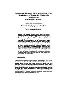
As explained in section 1, there is a need for enabling the usage of tools which support creative design. The goal is to better integrate different experts with background in creative design into the development process. This consideration affects not only the final implementation of the system, but rather all steps during the development process to ensure the usability of the system and the required quality of the user interface. Models are an excellent vehicle for integrating different stakeholders and different views on the system during the whole development process. Thus, in our vision, models are also used to integrate the different tools and the resulting products. Thereby the concepts from model-driven development, like explicit transformations, are applied for computer-supported transitions between tools and artefacts. This ensures consistency between the artefacts produced by heterogeneous tools and furthermore reduces effort as subsequent steps can start directly from earlier results instead of taking them over manually. Flash: Click-Dummy GUI Builder: Functional Prototype
Photoshop: Mock-Up Model
3D Authoring Tool: 3D Graphics
IDE: Code
Flash: Multimedia UI
Fig. 1. Models as central hub in the development integrating different specific development steps and tools.
Figure 1 visualizes this idea on models acting as such an “central hub”. The upper arrows contain examples for earlier development phases where prototypes
4
Andreas Pleuss, Arnd Vitzthum, Heinrich Hussmann
play a central role in interactive systems development. For example, Photoshop mock-ups (as described in section 3.2) can be used to select first ideas about the system to be developed. When this step is finished, transformations are used to transmit the significant abstract information from the mock-ups into the model where it can be used for further development steps, like creating corresponding Flash click-dummies (see section 3.1) for gaining more specific user feedback. During this step, additional abstract information about the system is added which should again be kept in a central place, i.e. in the model. Thus, it is important to allow transitions into both directions: extraction of relevant abstract information from the tools (kind of “reverse engineering”) and generation of artefacts for the desired tools based on the existing model information. The lower part of figure 1 shows examples for later development steps, such as implementation of a final release. Here, the kinds of tools are more diverse and depend on the application domain and the target platforms. Models can be used to distribute the final implementation on different tools optimized for realizing different aspects of the system. For example, in multimedia development with Flash, it is a common practice to develop the code for system’s application logic within an external programming IDE, instead of using the Flash authoring tool’s built-in code editor. In the following sections we describe four of the mentioned examples more in detail and present how the transitions between models and tools can be realized.
3
From Prototypes to Models
An important part of interactive systems development is the usage of prototypes. Standard tools for user interface designers and people with background in creative design are Adobe Photoshop and Adobe Flash. In the following we show as an example how the information from prototypes created with these two tools can be extracted into models. 3.1
Flash Click-Dummies
Flash is a professional authoring tool for the creation of multimedia applications. It especially supports the creation of vector-based 2D graphics and animations and provides easy integration of other media objects like sound and video. The file format for the Flash authoring tool is the proprietary FLA format. To execute a Flash application, it is compiled into the SWF format which is executed by the Flash player. The Flash player is available as plug-in for all common webbrowsers. Due to the possibility to create complex and individual visual user interfaces very quickly, Flash is often used as a tool for creating prototypes. In this section we focus on so-called click-dummies, i.e. (horizontal) prototypes which show a broad range of user interface screens of a visual application without any underlying functionality. Sometimes some basic application functionality is simulated through predefined visualizations. Therefore, and for the navigation between the
Integrating Heterogeneous Tools into Model-Centric Development
5
scenes, some user interface elements are (partially) enabled. This provides the user a good impression of the overall look and feel of the system and gives an idea of the intended task flow and overall functionality.
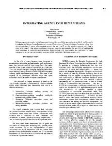
Timeline
Stage
Fig. 2. Screenshot of the Flash authoring tool (reduced to the most important elements.) On the stage, a part of a UI prototype is visible including individual graphics and standard widgets.
Using the Flash Authoring Tool for Creation of Click-Dummies. Figure 2 shows a screenshot of the Flash authoring tool. The tool is timeline-based, i.e. it uses the metaphor of a timeline to visualize the temporal aspect of Flash applications (important e.g. to support easy creation of animations). A timeline (upper window in fig. 2) contains a sequence of frames. Each frame can contain individual content, i.e. graphics, sound, video, text, or a Flash component such as a standard user interface widget (buttons, list boxes, text fields, etc.). In the authoring tool, the content of the currently selected frame is shown on the stage (centre window in fig. 2). The toolbar on the left hand side in figure 2 provides tools to create or modify the content on the stage, such as creating or editing 2D graphics or text on the stage. During the execution of a Flash application in the Flash player, the content of the frames is displayed. By default, the frames are shown successively according to their order on the timeline. However, it is also possible to stop the play-back of the timeline, which means that the content of the current frame remains on the stage (while it is still possible to interact with the elements in the displayed frame). Starting and stopping playback of the timeline as well as jumping to a specific frame can be controlled by scripting code. The scripting language provided in Flash is ActionScript, which is a complete programming language with object-oriented features. ActionScript
6
Andreas Pleuss, Arnd Vitzthum, Heinrich Hussmann
code can either be embedded within Flash documents directly, or can be specified in external class files (analogous to class files in Java). The Flash authoring tool enables very easy creation of click-dummies. A common way to realize the different screens of a click-dummy is to use a frame (on the timeline) for each screen. The content of a frame then corresponds to the content of a screen of the prototype. The navigation between the screens is realized just by a simple scripting command to jump to the respective frame in the timeline. For this purpose, usually a unique name is assigned to each frame. The creation of the content for the frames is very easy in Flash: standard widgets are just placed on the stage by dragging and dropping them from the component library. Individual graphical elements can be created using the comprehensive drawing and editing functionality of Flash. This is very beneficial if the prototype should contain individual graphical elements (e.g. information visualization) or if the prototype should simulate a platform where no conventional standard widgets are suitable (e.g. on TV devices). Other media objects can be imported into the tool and placed on the screen by drag’n drop as well. In this way, it is easy to integrate background images, which might also include screenshots or an image of the context of the application, like an image of the mobile device which should be the platform for the final system. Interaction can easily be added to the prototype by assigning event handling scripting code directly to the user interface elements on the stage. It is also easily possible to assign scripting code to a specific region within an image, which is useful for screenshots part of the prototype (e.g. it is possible to simulate interaction with a button on a mobile phone using an image of the mobile phone). Extracting information from Flash into a Flash model. A general problem when extracting information from a Flash document is the proprietary file format of Flash documents. We aim to deal with the FLA files, as they contain more information than the complied SWF files. To solve this problem we use the extension mechanism which exists for the Flash authoring tool. The extensions must be specified in JSFL, i.e. JavaScript using the JSFL library to access all elements in the authoring tool in terms of a kind of “document object model”, similar to DOM in web-browsers. JSFL allows creating, accessing and editing of Flash documents just like in the authoring tool. We have specified a JSFL script which walks through an arbitrary Flash document, accesses its content, and outputs it as a Flash model. For the Flash model, we use the Flash metamodel we proposed in [4]. The Flash metamodel is implemented with the Eclipse Modelling Framework (EMF ); the Flash models resulting from our JSFL plug-in are thus saved as an EMF-compliant XML file. Consequently, the resulting Flash model can be further processed using the conventional technologies from model driven engineering without any knowledge on JSFL or on the Flash authoring tool itself. Example Transformation from Flash Model to Abstract User Interface Model. A common concept to model user interfaces in an abstract way are
Integrating Heterogeneous Tools into Model-Centric Development
7
abstract user interface models as used in the user interface modelling community (see e.g. [5]). In other domains, like web-engineering, similar concepts are used. In an abstract user interface model the user interface consists of presentation units (abstraction of screens) which contain abstract user interface elements. Possible abstract user interface elements are input elements which allow the user to input information into the system (such as a text input), output elements which present some information to the user (such as a text label or an image), and action components which allow the user to invoke an action of the system without additional data input (such as a button). UI containers are used to structure the UI elements. (These elements are often further subdivided into more specific subtypes, like selection element, notification element, etc., depending on the specific modelling approach.) For abstract user interface models as described above, the transformation can be defined as follows: widgets in the prototype are mapped to the corresponding abstract user interface elements (text input to input component, button to action component, etc.). Videos and sounds are mapped to output components. 2D graphic objects are mapped to input components when they have assigned an event listener and otherwise to output components. Images are mapped to UI containers, as images might be screenshots which represent several UI components (the content of the UI container then can not be derived automatically from the model). Frames on the timeline are mapped to presentation units. The transitions between the presentation units can be derived by searching for script commands in the ActionScript code which specify the jumps to another frame. To ensure the success of the transformation, the designer is asked to comply to some conventions: first, the prototype must follow the explained timelinebased structure, instead of e.g. using external ActionScript code for the different screens (which is usually not useful for quick creation of prototypes, anyway). Second, the names for the frames representing screens have to follow a naming convention (e.g. a prefix “screen”) to distinguish them from other frames in the document. 3.2
Photoshop Mock-Ups
Photoshop is an image editing software which can be used for the very fast creation of user interface mock-ups, i.e. pictures of the user interface to present possible ideas about the user interface to the customer or the target user group. Based on the mock-ups the most promising approaches are selected and can then be further refined using more advanced prototypes e.g. created with Flash as described in section 3.1. The main advantage of using bitmaps (instead of e.g. GUI builders) is that any new and arbitrarily complex user interface can be visualized in very short time. The mock-ups are usually composed of different image pieces which are arranged and manipulated to create the desired new user interface. For standard widgets or user interface elements similar to already existing elements (like a dialogue window, a menu bar, or icons), the designer simply takes a screenshot of the desired element, cuts it, and integrates it in the mock-up. More individual elements, such as complex information visualization,
8
Andreas Pleuss, Arnd Vitzthum, Heinrich Hussmann
are drawn manually or put together from any other existing image snippets. Due to the unlimited flexibility of an image editing tool, any visual user interface can be composed in very short time, including user interfaces for new devices. If required, an image of the device (e.g. a mobile device) can also be part of the mock-up: the actual (software) user interface is then placed on the “screen” location within the image of the device which provides the user a good idea how the application will look like on the final device. After the usage of the mock-ups is finished and some user interfaces have been identified as promising, it is useful to capture the basic information from the mock-ups. As described in section 2, models in their role as “central hub” are an ideal instrument for this purpose. The most relevant information from the mock-ups are the user interface elements required for the user interface. Therefore, we provide a transition from the mock-ups to abstract user interface models as described in section 3.1. The identification of the type of user interface element requires some conventions for the designer: usually, each piece of image in a Photoshop document is put on a different layer (because otherwise it would not be possible to move it later within the whole image). By convention, the designer specifies the type and the name of the user interface element as the layer name (e.g. “address input” for an input component intended to input an address). Complex pieces which represent multiple user interface elements are specified as UI container. Technically, the transformation is performed by executing the built-in command “Save Layers...” in Photoshop which causes all layers to be saved on disk in separate files. The resulting file names then correspond to the layer names which contain by convention the type and the name of the user interface element. A simple Java application then collects the file names and creates a corresponding abstract user interface model. The model is used as base for further development steps, which may include, for instance, generating skeletons for a Flash click-dummy according to the mock-ups.
4
MML: From Models to Multimedia Authoring Tools
In the foregoing sections we discussed by the example of prototypes how in early development phases abstract model information can partially be derived from different external tools which support informal, creative design. In the following two sections we briefly present two existing examples showing how professional existing tools can be integrated into model-centric approaches to support creative tasks during the final implementation of the system. In this section we show how to integrate the Flash authoring tool for the final design of user interfaces and media objects within a model-driven development approach for multimedia applications. By the term “multimedia applications” we refer to applications which provide a individual, complex and interactive user interface using different kinds of media objects, like graphics, animation, sound and video. Classic examples are training and simulation applications, newer examples are infotainment systems in cars or home entertainment applications. The mod-
Integrating Heterogeneous Tools into Model-Centric Development
9
elling language used here is called Multimedia Modeling Language (MML) [6, 7], a platform-independent language for model-driven development of multimedia applications. Motivation for the language is the lack of a structured development process, claimed by many publications in this area. A specific problem of these applications are the different developer groups involved in the development process, as interactive multimedia applications require three different kinds of design: software design as current applications often include complex application logic, user interface design as the user interface is one of the core issues of the application and should often be individual and provide a high degree of usability, and media design which often requires large effort and specific expert knowledge. A design phase using models ensures the coordination between the different developer groups and their results. MML reuses concepts from UML, user interface modelling, and existing approaches for modelling of multimedia applications. It provides four kinds of models: the structural model specifies the structure of the application logic in terms of an UML class diagram. In addition, the model allows specifying media objects which are part of the system. The scene model mainly describes the presentation units (in multimedia context referred to as scenes) and the transitions between them. The abstract user interface model specifies the user interface for each scene in terms of abstract user interface elements similar as described in section 3.1. The abstract user interface elements are associated with classes or class properties from the structural model, e.g. an output component can represent a class attribute. In addition, media objects can be integrated into the user interface. Finally, the interaction model shows the main control flow in each scene based on events received from the abstract user interface elements or caused by media objects. MML is intended to allow transformations into code skeletons for any platform which supports multimedia user interfaces. However, particularly interesting is the idea to generate code skeletons for multimedia authoring tools like Flash. As described in [4], we perform this in several steps. The MML models are transformed into Flash models. For this purpose we have specified a Flash metamodel and a transformation. The Flash models are transformed into code skeletons: Flash documents (FLA files, generated using JSFL analoguous to section 3.1) which can be directly loaded into the Flash authoring tool and ActionScript code. For the application logic we use external ActionScript class files. Thus, the ActionScript code can be edited as any other object-oriented code e.g. within an IDE like Eclipse using Eclipse plug-ins for ActionScript support. The relationships between the elements in the Flash document and the ActionScript code are generated using JSFL, which ensures consistency with the model. The ActionScript code contains the properties from the class diagram including attributes and operation signatures. The operations have to be filled out by conventional programming in order to realize the application logic and to control the user interface objects and media objects they are associated with.
10
Andreas Pleuss, Arnd Vitzthum, Heinrich Hussmann
The generated Flash documents implement the overall structure of the application and contain the required standard widgets and placeholders for the media objects. In order to complete the application, the developer has to fill out the placeholders by selecting them on the stage and creating content inside them using all available functionality of the authoring tool in conventional way. Furthermore she arranges the filled-out placeholders and the generated widgets on the stage to create the final user interface layout. Of course, she is free to add any adornments, change the size and the appearance of the generated elements, or their type. As the navigation between the screens has been generated as well, it is possible to run and test the application immediately after generation. The described transformation has been implemented using the Atlas Transformation Language (ATL) and JSFL realizing the concepts described above (currently not including MML interaction models). First tests with MML have been run in several student projects. MML is currently not supported by its own visual modelling editor, but as a temporary solution we provide a plug-in for the UML tool MagicDraw supporting all types of MML models.
5
SSIML: From Models to 3D Authoring Tools
Just as multimedia system development, the creation of interactive 3D applications is an interdisciplinary activity. Different developer groups such as 3D content creators and programmers are involved in the development process. These groups use a variety of tools, such as 3D authoring tools and integrated development environments. Furthermore, a 3D user interface displaying 3D contents (represented by a so-called 3D scene which contains 3D objects) is often tightly coupled with the base application containing the application logic. Thus, these software components must seamlessly integrate with each other. Therefore concepts and tools are needed to support the collaboration of developers. The visual modeling language SSIML (Scene Structure and Integration Modelling Language) [8], which was developed by our research group, addresses this challenge. SSIML has the goal to facilitate the integration of 3D user interfaces into a broad spectrum of applications such as 3D product presentations and product configurators, virtual galleries, interactive 3D-manuals, 3D guides, Virtual Reality (VR) applications and even Augmented Reality (AR)-applications. The Visual Modeling Language SSIML and its Extensions. Unlike most conventional 3D development approaches, SSIML supports a model-based design prior to implementation. The elements of SSIML were specified in a MOFconform metamodel which was also mapped to a UML profile in order to allow an easy integration of SSIML into existing UML tools. SSIML allows a semi-formal and platform-independent specification of important 3D application parts. In particular, it offers different possibilities to interconnect complex-structured 3D contents (represented by a 3D scene) and application logic. One possibility for such an interconnection is the interrelation model
Integrating Heterogeneous Tools into Model-Centric Development
11
described below in this section. Thereby SSIML abstracts from implementationlevel details such as concrete geometries of 3D objects. SSIML provides a comprehensible and compact graphical notation which was designed to be easily understood by the different persons involved in the development process. Moreover, the visual SSIML models can not only serve as communication aid for the developers, but can also be used for documentation purposes. In order to reduce implementation errors and to save implementation time, platform-specific code skeletons can be generated automatically from the models. The basic SSIML language comprises two model types: the scene model and the interrelation model. The scene model allows describing the 3D scene structure (including all scene objects) and therewith the structure of the 3D user interface in a scene graph-oriented manner. A scene graph is a directed acyclic graph (DAG) representing the transformation hierarchy of the objects contained in the 3D scene. A scene object in SSIML is characterized by a unique name (e.g. table1), a content type identifier (e.g. Table), the type of the model element representing the 3D object (e.g. group, ’atomic’ object), its attributes (e.g. a transformation attribute) and - where applicable - by its children objects (e.g. a group tables could have two children: table1 and table2). In order to manage complex scene structures it is also possible to encapsulate whole subgraphs of a SSIML scene model in specialized nodes. Due to the high level of abstraction, 2D-scenes instead of 3D-scenes can be described using SSIML, even if we focus especially on 3D scenes. The interrelation model comprises the scene model, application components represented by UML classes and interrelations between classes and scene elements. For example, in the interrelation model one can specify that instances of a certain class are able to modify the transformation value of a specific 3D object (the transformation value represents the orientation, position and scale of an object in the three-dimensional space). Based on the core elements of SSIML we have defined several SSIML extensions, e.g. for the description of 3D object behavior [9] and task-dependent information presentation [10]. Partial results of an informal evaluation of an extended SSIML version (SSIML for Augmented Reality - SSIML/AR) were presented in [10].
Model-Centric Development with SSIML. Along with SSIML, we propose a sketch of a suitable development process. In this process three main developer roles are distinguished: software designer, 3D developer and programmer. The software designer creates the visual SSIML models. The design can be discussed with other development team members and can also be changed if necessary. Afterwards, platform-specific code is generated from the models. The scene model is translated into a so-called 3D template which is encoded e.g. in a 3D markup language such as VRML or X3D. The 3D developer is then able to import the 3D template into a 3D authoring environment and to enrich it with 3D contents such as concrete object geometries. The interrelations in the interrelation model
12
Andreas Pleuss, Arnd Vitzthum, Heinrich Hussmann
are transformed into program code, e.g. Java or C++ code. The programmer fills out the gaps in the generated program code. Since different code components in different languages (e.g. 3D markup language code, Java code) originate from the same SSIML model, the model can be seen as the central element in the SSIML development process. It represents a kind of contract between the different developer groups and therewith also ensures the consistency between (generated) code components. Ideally, from a model-centric point of view and as mentioned in section 1, modifications of the code should be also reflected by changes in the SSIML models and vice versa, while the consistency of the changed system would be checked automatically. It should be even feasible to integrate existing code components such as an existing 3D scene into a SSIML model. Unfortunately, the present SSIML tools (see below) only support forward engineering. However, at the end of this section we briefly sketch a possibility how an existing 3D scene can be translated back into a SSIML scene model. Present Tool Support. As mentioned above, we have defined a UML-profile based on the SSIML metamodel in order to enable the integration of SSIML into existing UML tools. We have integrated SSIML into the well-known UML tool MagicDraw , to name an example. In addition, this allows us encoding a SSIML model in the XML Metadata Interchange format (XMI), which is supported by a variety of UML tools. The XMI-format provides a suitable basis for the automatic translation of SSIML models into platform-specific code using XSLT stylesheets. More precisely, we have chosen X3D and VRML as target formats for automatically generated 3D code skeletons and Java as target language for the XSLT-based generation of program code. From the interrelations specified in a SSIML interrelation model we generate Java ’glue code’ in order to enable a seamless integration of the 3D scene into the corresponding overall application. Deriving SSIML Models from Existing 3D Scenes. As discussed in section 1, in some cases it might be useful to derive a model from an existing user interface prototype. In the context of SSIML this means that a SSIML model can be extracted from an already existing 3D scene which was created by a 3D content developer using a 3D authoring tool. As a first approach which actually takes into account an existing 3D scene, we have developed a validation tool which compares two 3D scenes in terms of their structure (object hierarchy, object types) and the naming of the contained 3D objects. After generating a 3D template from a SSIML scene specification, the tool allows checking if a present scene conforms to the generated template and therewith conforms to the SSIML model. The tool reports structural differences between the two 3D scenes. However, this approach still requires an existing abstract specification of the scene in a SSIML model. The next step would be to completely generate a SSIML model from a 3D scene which was already created with a 3D authoring tool. A suitable basis
Integrating Heterogeneous Tools into Model-Centric Development
13
for such a transformation is the X3D-format. X3D is the successor of VRML. X3D and VRML are standardized formats, integrate with different 3D platforms which provide VRML/X3D scene loaders (e.g. Java3D), can be imported and exported by many 3D authoring tools and are supported by several 3D format converters. Since X3D is an XML-based format, it is possible to translate an X3D scene into an XMI-encoded SSIML model using XSLT. Like SSIML, X3D uses a scene graph-oriented structure. Thus, the mapping between X3D and SSIML is quite straightforward. Names and types of SSIML elements can be derived from the names and types of corresponding elements of the X3D scene. A transformation of an X3D scene into a SSIML model should also preserve property values of scene objects (e.g. transformation and color values). Although these values are not visible in the SSIML diagram editor, they could be later incorporated again in a retranslation of an (adapted) SSIML model into X3D code or another 3D format.
6
Related Work
Important related work are the concepts from the user interface modelling community. While many approaches in this field are restricted to the usage of modelling tools or markup languages without specific tool support, some approaches basically allow the usage of visual user interface design tools. UsiXML [11] allows transformations between the different levels of abstraction which could help to extract abstract information from a concrete user interface model. [12, 13] provide reverse engineering for HTML-based user interfaces. User interface modelling tools like CanonSketch [14] integrate different views on the user interface models, including a concrete HTML view. Similarly, in domain specific tools for model-driven development, such as [15], GUI builders are integrated to visually specify the application’s user interface. However, concerning our goals, all approaches have in common that they are restricted to standard elements like HTML widgets. Similar restrictions exist (naturally) in the area of model-driven development of web-application (web-engineering). However, it is worth to note that some approaches in this area (e.g. [16, 17]) claim that the integration of existing tools for visual, creative user interface design is mandatory for the success of the development approach. As a consequence, they enable the usage of external web-design tools for the specification of the user interface design. In the field of 3D application development (e.g. Virtual Reality and Augmented Reality development) model-driven methods are rarely applied, although e.g. Smith et al. [18] underline the need of such approaches in the context of VR development. Nevertheless, some modelling approaches exist which allow the generation of platform-specific code (e.g. for interaction techniques [19] or presentation flows [20]) and are often directed towards a better support of developers without deeper experiences in programming such as designers [21]. However, all these approaches focus mainly on forward engineering and don’t consider a retranslation of an implementation level specification into a more abstract rep-
14
Andreas Pleuss, Arnd Vitzthum, Heinrich Hussmann
resentation. Furthermore, unlike in SSIML (see previous section), 3D contents have to be created independently from the modelling approaches and must be connected manually (by programming) with the code generated from the models. In the domain of multimedia applications, [22] presents a model-based approach for the development of training applications using the authoring tool Adobe Director. However, the transition between the models and the implementation in the tool has to be performed manually. In summary, several tendencies towards a better integration of tools for creative design and model-centric development exist, but there is clearly a lack of a more consequent and explicit integration of them, especially for earlier development steps like prototyping.
7
Conclusion and Outlook
In this paper, we have discussed a number of quite heterogeneous approaches, without providing much detail on each individual approach. The common theme among all the proposed tools is that there is an abstract software model on one side and an artefact of a concrete state-of-the-art commercial tool for user interface design on the other side. Both directions of transitions have been described: Creating artefact skeletons from the abstract model (forward engineering) as well as creating abstract views from artefacts (reverse engineering). Like in the traditional transitions between models and program code, the ideal world would be a “round trip” engineering between the levels. However, in the case of user interface design, it is also common to deal with many tool technologies at once. So a development may start from a user interface design (made in Photoshop), then derive an abstract interface model from it, create a skeleton for a Flash clickprototype from it, refine the abstract model based on some user studies, and finally make a transition towards Java code skeletons for a final implementation. The abstract model helps for establishing much more formal and traceable links between various design artefacts than in todays practice. Moreover, using the model as a central hub for transformations may in the long run help to reduce the (nowadays common) thinking in terms of one single design platform only, and therefore helps to introduce a more abstract way of thinking in projects where graphical designers and software designers work together. Of course, the prototypes for transformators which were mentioned above are far from being exhaustive and not yet well integrated. Nevertheless, they show that this is a road which is viable, and we will further elaborate the “model as design hub” idea in future work. The long-term vision is that import and export functions to and from abstract models will become standard features for any kind of design tool used in the development process.
References 1. Davis, F.D.: Perceived usefulness, perceived ease of use, and user acceptance of information technology. MIS Quarterly 13 (1989)
Integrating Heterogeneous Tools into Model-Centric Development
15
2. Cooper, A., Reimann, R.M.: About Face 2.0: The Essentials of Interaction Design. Wiley (2003) 3. Pleuß, A., van den Bergh, J., Sauer, S., Hußmann, H.: Workshop report: Model driven development of advanced user interfaces (mddaui). In: MoDELS Satellite Events. Springer (2005) 4. Pleuß, A., Hußmann, H.: Integrating authoring tools into model-driven development of multimedia applications. In: HCII’07. Springer (2007) to appear 5. Calvary, G., Coutaz, J., Thevenin, D., Limbourg, Q., Souchon, N., Bouillon, L., Florins, M., Vanderdonckt, J.: Plasticity of user interfaces: A revised reference framework. In: TAMODIA’02 Proc. INFOREC (2002) 6. Pleuß, A.: Modeling the User Interface of Multimedia Applications. In: MoDELS’05 Proc. Springer (2005) 7. Pleuß, A.: MML: A Modeling Language for Interactive Multimedia Applications. In: ISM’05 Proc. IEEE (2005) 8. Vitzthum, A., Pleuss, A.: SSIML: Designing structure and application integration of 3d scenes. In: Web3D’05 Proc. ACM Press (2005) 9. Vitzthum, A.: SSIML/behaviour: Designing behaviour and animation of graphical objects in virtual reality and multimedia applications. In: ISM’05 Proc. IEEE (2005) 10. Vitzthum, A.: SSIML/AR: A visual language for the abstract specification of augmented reality user interfaces. In: Proc. of 3DUI’06. IEEE (2006) 11. Limbourg, Q., Vanderdonckt, J., Michotte, B., Bouillon, L., L´ opez-Jaquero, V.: Usixml: A language supporting multi-path development of user interfaces. In: EHCI/DS-VIS Proc. Springer (2004) 12. Bouillon, L., Limbourg, Q., Vanderdonckt, J., Michotte, B.: Reverse engineering of web pages based on derivations and transformations. In: Proc.of 3rd Latin American Web Congress LA-Web2005, IEEE (2005) 13. Paganelli, L., Patern` o, F.: A tool for creating design models from web site code. International Journal of Software Engineering and Knowledge Engineering 13 (2003) 14. Campos, P.F., Nunes, N.J.: Canonsketch: A user-centered tool for canonical abstract prototyping. In: EHCI/DS-VIS Proc. Springer (2004) 15. Tangible Architect. http://www.tangiblearchitect.com (2007) 16. Hennicker, R., Koch, N.: Modeling the User Interface of Web Applications with UML. In: Practical UML-Based Rigorous Development Methods, Workshop of the pUML-Group held together with the UML2001, GI (2001) 17. Ceri, S., Fraternali, P., Bongio, A.: Web modeling language (webml): a modeling language for designing web sites. Computer Networks 33 (2000) 18. Smith, S.P., Duke, D.J., Willans, J.S.: Designing world objects for usable virtual environments. In: Workshop on Design, Specification and Verification of Interactive Systems 2000, Limerick (2000) 19. Willans, J.S., Harrison, M.D.: A toolset supported approach for designing and testing virtual environment interaction techniques. International Journal of HumanComputer Studies 55 (2001) 20. Ledermann, F.: An authoring framework for augmented reality presentations. Master’s thesis, Vienna Technical University (2004) 21. Dubois, E., da Silva, P.P., Gray, P.D.: Notational support for the design of augmented reality systems. In: DSV-IS Proc. Springer (2002) 22. Depke, R., Engels, G., Mehner, K., Sauer, S., Wagner, A.: Ein Vorgehensmodell f¨ ur die Multimedia-Entwicklung mit Autorensystemen. Informatik: Forschung und Entwicklung (1999)