Hindawi Publishing Corporation Advances in Artificial Intelligence Volume 2014, Article ID 739517, 9 pages http://dx.doi.org/10.1155/2014/739517
Research Article Intelligent Control for USV Based on Improved Elman Neural Network with TSK Fuzzy Shang-Jen Chuang, Chiung-Hsing Chen, Chih-Ming Hong, and Guan-Yu Chen Department of Electronic Communication Engineering, National Kaohsiung Marine University, Kaohsiung 81157, Taiwan Correspondence should be addressed to Chih-Ming Hong;
[email protected] Received 7 January 2014; Revised 7 April 2014; Accepted 22 April 2014; Published 18 May 2014 Academic Editor: Ant´onio Dourado Pereira Correia Copyright © 2014 Shang-Jen Chuang et al. This is an open access article distributed under the Creative Commons Attribution License, which permits unrestricted use, distribution, and reproduction in any medium, provided the original work is properly cited. In recent years, based on the rising of global personal safety demand and human resource cost considerations, development of unmanned vehicles to replace manpower requirement to perform high-risk operations is increasing. In order to acquire useful resources under the marine environment, a large boat as an unmanned surface vehicle (USV) was implemented. The USV is equipped with automatic navigation features and a complete substitute artificial manipulation. This USV system for exploring the marine environment has more carrying capacity and that measurement system can also be self-designed through a modular approach in accordance with the needs for various types of environmental conditions. The investigation work becomes more flexible. A catamaran hull is adopted as automatic navigation test with CompactRIO embedded system. Through GPS and direction sensor we not only can know the current location of the boat, but also can calculate the distance with a predetermined position and the angle difference immediately. In this paper, the design of automatic navigation is calculated in accordance with improved Elman neural network (ENN) algorithms. Takagi-Sugeno-Kang (TSK) fuzzy and improved ENN control are applied to adjust required power and steering, which allows the hull to move straight forward to a predetermined target position. The route will be free from outside influence and realize automatic navigation purpose.
1. Introduction During WWII, there were reported records of unmanned vessels for reducing the damages of vessels as well as injuries and fatality of human. Using small torpedos or larger-sized unmanned ships for collecting information [1], global positioning system (GPS) brings high efficiency through the use of low-cost, unmanned design. There is no need for the concern of pilot’s safety in using unmanned vehicles for marine environmental survey. Vessels for marine environmental survey are usually equipped with USV system. It allows heavier loading capacity. In addition, the design of vessels can be modularized. There is better flexibility for adjustment according to the needs from various types of environments and investigations. The effective control range of many USV systems varies from 50 meters to 30 kilometers [2, 3], mainly restrained by the wireless transceiver modules. In order to increase the
effective working range of USV, a design of unmanned vessels would be necessary. To allow USV systems to be autonavigating and to replace manual operation completely, the autonavigation system is the most needed task for every unmanned carrier. The Elman neural network (ENN) was first proposed for speech processing. Generally, the ENN can be considered as a special kind of feed-forward neural network with additional memory neurons and local feedback. Because of the context neurons and local recurrent connections between the context layer and the hidden layer, it has certain dynamic advantages over static neural network, such as multilayer perceptrons and radial-basis function networks. It also makes ENN very suitable to be applied in the neurocontrol field. However, the typical ENN cannot approximate high-order dynamic systems closely, and its convergence speed is usually slow and not suitable for time-critical applications. Several kinds of modified ENNs were proposed to overcome such issues
2
Advances in Artificial Intelligence
Server PC USV Wi-Fi AP GPS
Power motor cRIO
Direction sensor
Steering servomotor
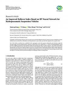
Figure 1: System architecture.
to improve the dynamic characteristics and convergence speed of the original ENN [4, 5]. Compared with BP neural network, ENN has many advantages: faster convergence speed, less training iteration, stronger robustness, no local minimum, and so forth. On the other hand, the method of fuzzy inference proposed by Sugeno and Kang [6], which is known as the Takagi-Sugeno-Kang (TSK) model in fuzzy systems literature, has been one of the major topics in theoretical studies and practical applications of fuzzy modeling and control. The basic idea of this method is to decompose the input space into fuzzy regions and to approximate the system in every region by a simple model. The overall fuzzy model is thus considered as a combination of interconnected subsystems with simpler models.
Figure 2: Global positioning system [7].
2. Research Methods The designed vehicle’s overall system architecture includes a high precision programmable controller-cRIO as main core, a global satellite positioning receiver developing module (GPS receiver module), a direction sensor, a steering servomotor, and power motor, which are all shown in Figure 1. 2.1. Unmanned Surface Vehicle. The main body of USV in this paper is a catamaran-type boat which was designed and built by students and teacher of Department of Naval Architecture and Ocean Engineering, National Kaohsiung Marine University. This catamaran is 5.27 meters long, 1.74 meters wide, and 1.17 meters high, and the electric motor to drive the power can carry 5∼6 passengers. Using a catamaran design as an USV has the following main features: (1) sea wave balance performance is better; (2) low-speed navigation and rotation of the catamaran are better; (3) it has a flat usable space and is easier to allocate required instruments to conduct measurement work. The designed USV provides more flexible space to install various equipment (e.g., water quality monitoring meter, fish finder machine, anemometer, wind direction sensor module, etc.), to establish marine environmental data collection. A large solar panel installed on top of the hull can strengthen sailing range.
Figure 3: GPS receiver.
2.2. Global Positioning System. Global positioning system (GPS) is a combination of satellites and wireless communication technology as shown in Figure 2. GPS is a globalization and all-purpose system which has many important features, like all-weather function, being easy to operate, high economic efficiency of navigation positioning, and timing systems. Its advantages include all-weather function free from any interference, global coverage up to 98%, three-dimensional fixed constant speed precision, time-saving, high efficiency, widely used, versatile, and mobile positioning [10]. In this paper, the GPS receiver used (Figure 3) to receive GPS satellite signals is manufactured by ICP DAS Company, model GT-321R. Using RS-232 serial port, protocol setting as 4800 bps baud rate and 8-N-1 format. The four messages to retrieve mainly including longitude, latitude, speed and time, so NMEA information output format (GPRMC) message was chosen as the designed USV position information in the marine environment and sailing speed. 2.3. Direction Sensor. Direction sensor is called the electronic compass (e-compass), the most suitable range for the Earth’s magnetic field detection. DC static magnetic field can be detected; it can detect the magnetic field strength and direction. Earth’s magnetic field strength of 0.5 to 0.6 gauss can be simplified as shown in Figure 4 of bipolar magnetic field, which is equivalent along centre of the earth.
Advances in Artificial Intelligence
3
Top view:
X
Figure 4: Earth’s magnetic field.
Z
Y
Figure 6: Installation diagram of direction sensor.
Figure 5: Direction sensor [8].
Electronic compass pointing along the local magnetic field determines the direction, the direction of the local magnetic north usually. Because the magnetic north and true north are not the same, so the magnetic north and true north are not usually together. The local magnetic variation is called magnetic declination (declination angle). It is a simple description of the magnetic north and geographic north difference between the angles, expressed as easterly or westerly direction. Electronic compass which suffered all kinds of interference can be broadly divided into two categories. (1) Hard Iron Interference. Fixed-intensity magnetic interferences, such as sensor surrounding the original electronic parts, such as speakers, microphones, batteries, panels, and metal shield, will release a fixed magnetic force to influence the electronic compass of reading. Calibration must be done to zero. (2) Soft Iron Interference. It will change the intensity and direction or can distort the magnetic field lines of interfering substances, such as battery electricity consumption changes in the user’s environment; surrounding the original electronic parts of interference depends on precision quasi-level specifications to determine the need for correction [11]. The UM6 ultraminiature orientation sensor measuring orientation in all three dimensions at 500 Hz using a combination of rate gyros, accelerometers, and magnetic sensors was applied to monitor sailing direction as shown in Figure 5. The direction sensor was mounted on designed USV and was along with the direction of the boat as shown in Figure 6. Hence, the Earth’s magnetic field and USV sailing direction will be identical.
2.4. Controller Core System. Thinking of sea environment, we must pay more attentions to choose a more reliable computer as the unmanned vehicle controller, and the selected controller’s capability must meet the basic requirements for the processing speed and vibrations from outside interference. And it must withstand higher temperature ranges. Due to the fact that the complexity of autopilot operation is very high, and the wave on sea level is greater, the calculation ability and processing speed of central controller must be considered. National instruments’ CompactRIO (cRIO) is quite applicable to the previous requirements. The selected cRIO is a programmable automation controller (programmable automation controller, PAC), a low-cost, reconfigurable control, and acquisition system for the need for efficient performance and reliability applications is designed. The system is done through a small, rugged, industrial-grade hot-swappable input and output (input/output) module, not only cRIO to have industrial-grade architecture, but also can be placed in the factory or under inclement environment ensure that the system the reliability [12]. In this system, due to the need of external input for receiving control commands, (1) RS-232 serial transmission (GPS receivers, direction sensors, and left turn servomotor), (2) DO digital signal output (status display), (3) AO analog output (power output of the motor for control), selected interface card must comply with the previous specifications. Three module adapter cards in this optional module for national Instruments’ CompactRIO are, respectively, NI9870, NI-9403, and NI-9263. Each module card into NI-9074 chassis has been shown in Figure 7. 2.5. Steering Mechanism. In this paper, a small boat which can afford 5∼6 passengers and has outboard rudder with DC motor as power is adopted as USV main body. In order to achieve unmanned automatic navigation function, a mechanical device must be driven on the steering wheel to take control of sailing direction. Therefore, in this paper Mitsubishi
4
Advances in Artificial Intelligence User’s application layer
Notebook
AP
Linking layer
GPS Servomotor NI-9870 USV system layer
Figure 7: cRIO hardware platform. cRIO-9074
Direction sensor Status indicators
NI-9403
NI-9263
Brushless motor
Figure 9: Architecture of the unmanned automatic system.
Figure 8: MR-J2S-10A servomotor [9].
MR-J2S-10A servomotor is used to drive, as shown in Figure 8. A servomotor with high precision position control and baud rate of 9600 bps via an RS-232 serial port by way of torque and speed control is adopted in this design.
3. Architecture and Research Method There are three layers in the system architecture, as shown in Figure 9. The first layer is the user’s application interface of the console. It is for perception of voyage information or delivery of mission commands. The second layer is the linking layer for interconnection. This is for data transmission between the two ends, via wireless network stations. The third layer is the system layer—the core of this unmanned autonavigation system. It controls the steering and dynamic of the whole body through precise calculation. Chi-Chin harbor is the site where testing of autonavigation in this experiment was conducted. The test vessel is a double-hull boat, designed by the department of naval architecture and ocean engineering, and is equipped with a brushless outboard motor as the engine of the vessel. The primary sensing instruments used in the test are GPS and orientation sensor, and cRIO-9074 is used for calculation and justification of the automatic navigation system to control the steering and power-output of the outboard motor. GPS of the autonavigation system is installed on top of the vessel, as
Figure 10: Illustration of layout of equipment.
shown in Figure 10. The orientation sensors are installed in front of the cockpit, in line with the orientation of the vessel body.
4. Design of Control Algorithm Based on Improved ENN with TSK Fuzzy In order to design the automatic navigation control system without sea wave inferences, a lot of efforts are used to design the fuzzy and neural network control. Hence, fuzzy control process proceeds to the amount of control requirement [13, 14]. Intelligent control of nonlinear systems capable of handling and uncertainty, especially in the comparison of PID and fuzzy control, using the fastest design of neural network control, even in the output control can improve accuracy [15], so in this fuzzy neural network control theory will be used as an automatic navigation system control. 4.1. Improved Elman Neural Network (ENN) Controller. The architecture of the proposed improved ENN including
Advances in Artificial Intelligence
5 where 𝑥𝑖(1) , 𝑥𝑟(3) are input and 𝑥𝑗(2) (𝑘) is output of the hidden
Ref. angle + −
layer. 𝑥𝑟(3) (𝑘) is also the output of the context layer; 𝑊𝑖𝑗 and 𝑊𝑟𝑗 are the connecting weights of input neurons to hidden neurons and context neurons to hidden neurons, respectively.
Rudder angle
USV
Supervised learning law
Layer 3: Context Layer. In the context layer, the node input and output are represented as
yo(4) Output layer o Wjo
𝑥𝑟(3) (𝑘) = 𝛼𝑥𝑟(3) (𝑘 − 1) + 𝑥𝑗(2) (𝑘 − 1) ,
Σ
where 0 ≤ 𝛼 < 1 is the self-connecting feedback gain. xj(2)
−1
−1
Z
Z
−1
Z
···
S
S
Wrj
Layer 4: Output Layer. In the output layer, the node input and output are represented as
Hidden layer S j Wij
x(3) r
(4) 𝑦𝑜(4) (𝑘) = 𝑓𝑜(4) (net(4) 𝑜 (𝑘)) = net𝑜 (𝑘) ,
−1
Z−1 𝛼
Z 𝛼 Context layer r
Input layer i
−1
Z 𝛼
Figure 11: Architecture of the improved ENN.
the input layer, the hidden layer, the context layer, and the output layer with two input nodes, nine hidden nodes, and one output node is shown in Figure 11, where the control law is defined as rudder angle, and the two ENN inputs are 𝑒1(1) and 𝑒2(1) with 𝑒1(1) = 𝑒(𝑘) and 𝑒2(1) = 𝑐𝑒(𝑘) = 𝑒(𝑘) − 𝑒(𝑘 − 1), the change of error. For the 𝑘th sampling instant, the error can be expressed as angular deviation 𝑒(𝑘) = 𝜃𝑟∗ (𝑘) − 𝜃𝑟 (𝑘). The proposed ENN [4, 5] takes the feedback into account, and better learning efficiency can be obtained. Moreover, to make the neurons sensitive to the history of input data, self-connections of the context nodes and output feedback node are added. So the proposed ENN has the ability to deal with nonlinear problems and can effectively improve the convergence precision and reduce the learning time. The signal propagation and the basic function in each layer are introduced below. Layer 1: Input Layer. In the input layer, the node is defined by 𝑥𝑖(1)
(𝑘) =
𝑓𝑖(1)
(net(1) 𝑖
(𝑘)) =
net(1) 𝑖 ,
𝑖 = 1, 2,
Layer 2: Hidden Layer. In the hidden layer, the node is defined by (1) (3) net(2) 𝑗 = ∑ 𝑊𝑖𝑗 × 𝑥𝑖 (𝑘) + ∑ 𝑊𝑟𝑗 × 𝑥𝑟 (𝑘) ,
𝑥𝑗(2) (𝑘) =
1+
exp (−net(2) 𝑗 )
,
𝑗 = 1, 2, . . . , 9,
1 1 2 𝐸 = (𝜃𝑟∗ − 𝜃𝑟 ) = 𝑒𝐿2 , 2 2
(5)
where 𝜃𝑟∗ and 𝜃𝑟 represent the angle output reference and actual angle output of the USV, respectively, and 𝑒𝐿 denotes the tracking error. The learning algorithm is described below. Layer 4: Update Weight 𝑊𝑗𝑜 . The error term to be propagated is given by 𝛿𝑜 = −
𝜕𝐸 𝜕net(4) 𝑜
= [−
𝜕𝐸
𝜕𝑦𝑜(4)
𝜕𝑦𝑜(4) 𝜕net(4) 𝑜
].
(6)
Then the weight 𝑤𝑗 is adjusted by the amount Δ𝑊𝑗𝑜 = −
(4) 𝜕net(4) 𝜕𝐸 𝜕𝐸 𝜕𝑦𝑜 𝑜 = [− (4) ] ( ) = 𝛿𝑜 𝑥𝑗(2) 𝜕𝑊𝑗𝑜 𝜕𝑊 𝜕𝑦𝑜 𝜕net(4) 𝑗𝑜 𝑜 (7)
and updated by
𝑟
1
4.2. Online Supervised Learning and Training Process. Once the improved ENN has been initialized, supervised learning is used to train this system based on gradient descent theory. The derivation is the same as that of the backpropagation (BP) algorithm. It is employed to adjust the parameters of the ENN by using the training patterns. By recursive application of the chain rule, the error term for each layer is first calculated. The adaptation of weights to the corresponding layer is then given. The purpose of supervised learning is to minimize the energy function 𝐸 expressed as [16]
(1)
where 𝑘 represents the kth iteration; 𝑒𝑖(1) (𝑘) and 𝑥𝑖(1) (𝑘) are the input and the output of the layer.
𝑖
𝑗
where 𝑊𝑗𝑜 is the connecting weight of hidden neurons to output neurons and 𝑦𝑜(4) (𝑘) is the output of the improved ENN and also the control law of the proposed controller.
ei(1)
(1) net(1) 𝑖 = 𝑒𝑖 (𝑘) ,
(4)
(2) net(4) 𝑜 (𝑘) = ∑𝑊𝑗𝑜 × 𝑥𝑗 (𝑘) ,
x(1) i ···
(3)
(2)
𝑊𝑗𝑜 (𝑘 + 1) = 𝑊𝑗𝑜 (𝑘) + 𝜂1 Δ𝑊𝑗𝑜 , where 𝜂1 is the learning rate.
(8)
6
Advances in Artificial Intelligence
Layer 3: Update Weight 𝑊𝑟𝑗 . By using the chain rule, the update law of 𝑊𝑟𝑗 is (2)
(4) 𝜕𝑥𝑗 𝜕net(4) 𝜕𝐸 𝜕𝐸 𝜕𝑦𝑜 𝑜 = [− (4) ] ( ) Δ𝑊𝑟𝑗 = − (4) (2) 𝜕𝑊𝑟𝑗 𝜕𝑦𝑜 𝜕net𝑜 𝜕𝑥𝑗 𝜕𝑊𝑟𝑗
(9)
= 𝛿𝑜 𝑊𝑗𝑜 𝑥𝑗(2) [1 − 𝑥𝑗(2) ] 𝑥𝑟(3) . The connecting weight 𝑊𝑟𝑗 is updated according to 𝑊𝑟𝑗 (𝑘 + 1) = 𝑊𝑟𝑗 (𝑘) + 𝜂2 Δ𝑊𝑟𝑗 ,
(10)
where 𝜂2 is the learning rate. Layer 2: Update Weight 𝑊𝑖𝑗 . By using the chain rule, the update law of 𝑊𝑖𝑗 is (2)
(4) 𝜕𝑥𝑗 𝜕net(4) 𝜕𝐸 𝜕𝐸 𝜕𝑦𝑜 𝑜 = [− (4) ] ( ) Δ𝑊𝑖𝑗 = − 𝜕𝑊𝑖𝑗 𝜕𝑦𝑜 𝜕net(4) 𝜕𝑥𝑗(2) 𝜕𝑊𝑖𝑗 𝑜
(11)
= 𝛿𝑜 𝑊𝑗𝑜 𝑥𝑗(2) [1 − 𝑥𝑗(2) ] 𝑥𝑖(1) .
𝑊𝑖𝑗 (𝑘 + 1) = 𝑊𝑖𝑗 (𝑘) + 𝜂3 Δ𝑊𝑖𝑗 ,
(12)
where 𝜂3 is the learning rate. 4.3. Takagi-Sugeno-Kang (TSK) Fuzzy Controller. Typically, a TSK fuzzy model consists of IF-THEN rules that have the following form: 𝑅𝑖 : if 𝑥1 is 𝐴𝑖1 , 𝑥2 is 𝐴𝑖2 , . . ., and 𝑥𝑛 is 𝐴𝑖𝑛 , then ℎ𝑖 = 𝑓𝑖 (𝑥1 , 𝑥2 , . . . , 𝑥𝑛 ; 𝑎𝑖 ) = 𝑎𝑜𝑖 + 𝑎1𝑖 𝑥1 + ⋅ ⋅ ⋅ 𝑎𝑛𝑖 𝑥𝑛 .
(13)
For 𝑖 = 1, 2, . . . , 𝐶, where 𝐶 is the number of rules, 𝐴𝑖𝑗 is the fuzzy set of the 𝑖th rule for 𝑥𝑗 with the adjustable parameter set 𝜃𝑗𝑖 , and 𝑎𝑖 = (𝑎0𝑖 , 𝑎1𝑖 , . . . , 𝑎𝑛𝑖 ) is the parameter set in the consequent part. The predicted output of the fuzzy model is inferred as [16] ∑𝐶𝑖=1 ℎ𝑖 𝑤𝑖 ∑𝐶𝑖=1 𝑤𝑖
𝑚𝑖 =
2𝑖 − 1 , 𝑁
(15)
2 , 𝑁
(16)
𝜎𝑖 =
The connecting weight 𝑊𝑖𝑗 is updated according to
𝑦̂ =
(i.e., 𝜃𝑗𝑖 ) include 𝑚𝑖𝑗 and 𝜎𝑖𝑗 , which are the center (or mean) and the width (or variance) of the Gaussian membership function of the 𝑖th rule at 𝑗th dimension, respectively. Both the premise parts (i.e., 𝜃𝑗𝑖 ) and the consequent parts (i.e., 𝑎𝑖 ) in a TSK fuzzy model are required to be identified [17, 18]. The considered problem is to obtain correct distribution of fuzzy rules and its corresponding polynomial from a set of observations. The input-output pairs are {(𝑥1 , 𝑦1 ), (𝑥2 , 𝑦2 ), . . . , (𝑥𝑁, 𝑦𝑁)}, where 𝑥𝑘 = 𝑘/𝑁 is normalization ̃𝑝 (𝑘)) is the of 𝑘th subcarrier channel number; 𝑦𝑘 = real(𝐻 real part (or imaginary part) of the corresponding channel transfer function. We assume that those observations are obtained from an unknown function 𝑦𝑘 = 𝑓(𝑥𝑘 ). We want to construct a TSK model that can accurately represent 𝑓 in terms of input-output relationship. In order to simplify the algorithm and loose the compute burden, we fix the number of rules as 𝐶 = 𝑁/2 and the parameters of each rule as
,
(14)
where ℎ𝑖 is the output of the 𝑖th rule; 𝑤𝑖 = min𝑗=𝑖,𝑖+1,...,𝑛 𝐴𝑖𝑗 (𝜃𝑗𝑖 ; 𝑥𝑗 ) is the 𝑖th rule’s firing strength, which is obtained as the minimum of the fuzzy membership degrees of all fuzzy variables. There are many choices for the types of membership functions, such as triangular, trapezoidal, or Gaussian. In this paper, a Gaussian membership function is employed for two reasons. Firstly, a fuzzy system with Gaussian membership function has been shown to approximate any nonlinear functions on a compact set. Secondly, a multidimensional Gaussian membership function generated during the learning process can be easily decomposed into the product of 1D Gaussian membership functions. Choosing Gaussian membership function, in (16), the parameters of the premise parts
where 𝑚𝑖 and 𝜎𝑖 are the center and width of the membership function, respectively. The fire strength of each input represents the degree 𝑥𝑘 belonging to the corresponding rule. Since the input is one dimension, the fire strength can be calculated by 2
2
𝐹𝑖 = 𝑒−[(𝑥𝑘 −𝑚𝑖 ) /𝜎𝑖 ] .
(17)
Since the normalized firing strength is employed, the 𝑤𝑖 in (14) can be defined as 𝑤𝑖 =
𝐹𝑖 . ∑ 𝐹𝑖
(18)
Furthermore, the parameters of each rule are fixed; the only adjustable parameter of TSK model is 𝑎𝑖 in (13). The parameter is updated by the following rule: 𝑎𝑖 (𝑡 + 1) = 𝑎𝑖 (𝑡) + 𝜂 [𝑦̂𝑘 − 𝑦𝑘 ] 𝑥 (𝑘) 𝑤𝑖 ,
(19)
where 𝑥(𝑘) is input vector [1, 𝑥𝑘 ], 𝜂 is the learning rate, and 𝑦̂𝑘 is the current output of fuzzy model calculated using (14). Finally, the procedure of the used TSK learning algorithm is described as follows. Step 1. Define the fuzzy rule in (15) and (16); the initial value of 𝑎𝑖 is set to be [1, 1]. Step 2. The first snapshot of all-pilot subcarriers is used to train the in 𝑎𝑖 (13) to (19). When the error is small enough, then go to Step 3. Step 3. Estimate the channel transfer function using (13) to (18). When the input is at pilot symbol channel, 𝑎𝑖 is updated to trace the variation of channel. A block diagram of the TSK fuzzy controller is presented in Figure 12. The power control with a processing flowchart is shown in Figure 13.
Advances in Artificial Intelligence
7
Table 1: Test of linear acceleration. Start
Task Average speed (NM) 0 1.7 1.9 2.3 2.5
Power (%) 20 40 60 80 100
“Angular deviation, current speed, and previous power output” signal
TSK fuzzy of power output Fuzzy rule
Fuzzification
Fuzzy reasoning
Defuzzification
Yes
Angular deviation Current speed
No
Reach final point
Power output
End
Previous power output
Figure 13: Flowchart of TSK fuzzy control. Figure 12: Block diagram of TSK fuzzy control of power output.
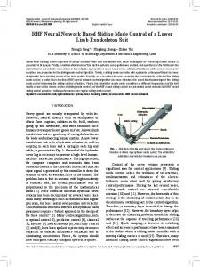
For obtaining the basic dynamic data of the boat, it is necessary to test the boat in driving along a straight line and in turning directions. Before the design of an unmanned autonavigation, it is required to figure out the dynamic power for controlling the speed of the boat as well as the steering characteristics and adequate turning speeds. After collection of required data, design and programming of improved ENN with TSK fuzzy control can then be preceded. The cRIO9074 and computer are installed on the boat to record boat’s relevant data. The speed data of the boat is obtained via GPS, and computer is used to control the power output. 5.1. Straight Movement. Data about the dynamic of linear acceleration is collected during the test. As illustrated in Figure 14, it is revealed that the boat’s main speed range is mainly 1.8∼2.5 NM/h. Due to the design of double-hulled frame and a weight of 1.3 tons, the maximum speed is no more than 3 NM/h. Moreover, even at low startup speed, initiated with 30% maneuver power, it took a bit longer time to achieve working speed. From Table 1, it is clear that by controlling the power in the range of 50∼85%, vessel per hour sailing is around 1.8∼ 2.4 NM/h, which is more stable in movement. 5.2. Turning Radius. When testing turning movement, the main method is to test speeds in segmentation to obtain the radius for turning the boat for 360∘ . From our result, it is obvious that at 40% of power output, the turning of the boat is almost spinning on the spot. It reveals the better stability with the design of the double-hulled frame. Nonetheless, the
100 75
2
50 1
0
Power (%)
5. Test of the Unmanned Automatic System
Speed (knot)
3
25
0
30
60 Time (s)
90
0 120
Speed Power
Figure 14: Test of linear acceleration.
power output should be greater than 40% relatively effective performance if there is the need for moving forward while turning.
6. Experimental Results The automatic navigation design is shown in the diagram of Figure 12; the module of improved ENN control is needed for modification of orientation if the boat is deviating from its navigated direction. In addition, for the control of power output, data about angular deviation, current speed, and previous power are required for maintaining the boat at working speed through TSK fuzzy control. The USV automatic navigation test begins with inputs of destined navigating points, as illustrated in Figure 15, and then the information is transmitted to the cRIO-9074 system
8
Advances in Artificial Intelligence 3
Improved ENN with TSK fuzzy method
Tracking distance error (m)
Angular response (s)
𝑋/𝑌 position response (s)
±2.5
350
600
100 75
2
50 1
0
Power (%)
Method
Speed (knot)
Table 2: Performance of proposed control method.
25
0
60
120 180 Time (s)
240
0 300
Speed Power
Figure 17: Navigation data of power and speed. 180
Figure 15: Command panel of PC sever.
Angle (∘ )
90 0 −90 −180
60
0
120
180 Time (s)
240
300
Target declination Ship declination
Figure 18: Data of target declination and boat declination.
to keep on the navigated direction. The performance of proposed control method is summarized in Table 2.
Figure 16: Navigation route.
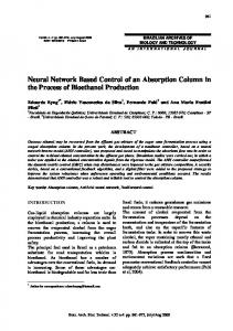
on the boat. When the server presses the “automatic navigation” button, the boat begins a voyage along the destined navigating points. Data transmitted back from cRIO-9074 includes power outputs, speeds, and tracks of the boat for realization of the navigation conditions. It is obviously illustrated in Figure 16 that USV follows the destined route successfully in navigation. Figure 17 shows the navigation data of this test trip. It reveals clearly that the boat successfully followed the design of TSK fuzzy control, to maintain the speed of moving straight forward at around 2.2 NM/h and speeds of turning at around 1.8∼2 NM/h. When turning, it is demonstrated in Figure 18 that the boat declination has followed the target declination. It is also clearly illustrated that when the boat was ordered to turn at 90 seconds, it did adjust the orientation effectively
7. Conclusion This study uses a platform developed by the department of naval architecture for the autonavigation system, using GPS, orientation sensors, and cRIO-9074, as well as combining LabView and intelligent control algorithm, to reduce the cost of sensors and time of system development effectively. For the autonavigation system, there are two sets of intelligent control algorithm, designed for power output and steering of this electric double-hulled boat, to control the boat stably to travel along the navigation route. As the wave heights in Chi-Chin harbor vary dramatically, the test results show that the double-hulled boat has pretty good stability and keeps steering control. The task of autonavigation could be easily and nicely performed.
Conflict of Interests The authors declare that there is no conflict of interests regarding the publication of this paper.
Advances in Artificial Intelligence
References [1] B. Volker, Unmanned Surface Vehicles—A Survey, Skibsteknisk Selskab, Copenhagen, Denmark, 2008. [2] C. S. Huang, An ambulate wireless control robotic arm in the application of anti-explosion [M.S. thesis], I-Shou University, Taiwan, 2008. [3] H. F. Kuo, Design and implementation of a remotely controlled robot-car with real-time image identification technique for object tracking [M.S. thesis], National Cheng Kung University, 2006. [4] X. Li, G. Chen, Z. Chen, and Z. Yuan, “Chaotifying linear Elman networks,” IEEE Transactions on Neural Networks, vol. 13, no. 5, pp. 1193–1199, 2002. [5] F.-J. Lin and Y.-C. Hung, “FPGA-based elman neural network control system for linear ultrasonic motor,” IEEE Transactions on Ultrasonics, Ferroelectrics, and Frequency Control, vol. 56, no. 1, pp. 101–113, 2009. [6] M. Sugeno and G. T. Kang, “Structure identification of fuzzy model,” Fuzzy Sets and Systems, vol. 28, no. 1, pp. 15–33, 1988. [7] Global Positioning System, http://hep.ccic.ntnu.edu.tw/. [8] CHR-UM6 Direction Sensors, http://www.chrobotics.com/. [9] MR-J2S-A, http://www.two-way.com.tw/html/product/. [10] S. H. Tsao, Research and development of unmanned aerial vehicle control software [M.S. thesis], National Defense University, 2009. [11] Acceleration Sensor and Electronic Compass Principle Introduced, http://www.seraphim.com.tw/upfiles/c supports01328152963.pdf. [12] NI CompactRIO, http://www.ni.com/compactrio/zht/whatis .htm. [13] S. C. Liu, Automatic navigation of a wheeled mobile robot using particle swarm optimization and fuzzy control [M.S. thesis], National Central University, 2011. [14] Y. H. Lin, Integrated flight path planning system and flight control system for navigation and guidance of unmanned helicopter [M.S. thesis], National Cheng Kung University, 2009. [15] C. M. Hong, T. C. Ou, and K. H. Lu, “Development of intelligent MPPT control for a grid-connected hybrid power generation system,” Energy, vol. 50, pp. 270–279, 2013. [16] C. T. Lin and C. S. G. Lee, Neural Fuzzy Systems, Prentice-Hall, 1996. [17] S. X. Yang, H. Li, M. Q.-H. Meng, and P. X. Liu, “An embedded fuzzy controller for a behavior-based mobile robot with guaranteed performance,” IEEE Transactions on Fuzzy Systems, vol. 12, no. 4, pp. 436–446, 2004. [18] T.-M. Wang, P.-C. Lin, H.-L. Chan, J.-C. Liao, T.-W. Sun, and T.-Y. Wu, “Energy saving of air condition using fuzzy control system over Zigbee temperature sensor,” in Proceedings of the 24th IEEE International Conference on Advanced Information Networking and Applications Workshops (WAINA ’10), pp. 1005– 1010, April 2010.
9
Journal of
Advances in
Industrial Engineering
Multimedia
Hindawi Publishing Corporation http://www.hindawi.com
The Scientific World Journal Volume 2014
Hindawi Publishing Corporation http://www.hindawi.com
Volume 2014
Applied Computational Intelligence and Soft Computing
International Journal of
Distributed Sensor Networks Hindawi Publishing Corporation http://www.hindawi.com
Volume 2014
Hindawi Publishing Corporation http://www.hindawi.com
Volume 2014
Hindawi Publishing Corporation http://www.hindawi.com
Volume 2014
Advances in
Fuzzy Systems Modelling & Simulation in Engineering Hindawi Publishing Corporation http://www.hindawi.com
Hindawi Publishing Corporation http://www.hindawi.com
Volume 2014
Volume 2014
Submit your manuscripts at http://www.hindawi.com
Journal of
Computer Networks and Communications
Advances in
Artificial Intelligence Hindawi Publishing Corporation http://www.hindawi.com
Hindawi Publishing Corporation http://www.hindawi.com
Volume 2014
International Journal of
Biomedical Imaging
Volume 2014
Advances in
Artificial Neural Systems
International Journal of
Computer Engineering
Computer Games Technology
Hindawi Publishing Corporation http://www.hindawi.com
Hindawi Publishing Corporation http://www.hindawi.com
Advances in
Volume 2014
Advances in
Software Engineering Volume 2014
Hindawi Publishing Corporation http://www.hindawi.com
Volume 2014
Hindawi Publishing Corporation http://www.hindawi.com
Volume 2014
Hindawi Publishing Corporation http://www.hindawi.com
Volume 2014
International Journal of
Reconfigurable Computing
Robotics Hindawi Publishing Corporation http://www.hindawi.com
Computational Intelligence and Neuroscience
Advances in
Human-Computer Interaction
Journal of
Volume 2014
Hindawi Publishing Corporation http://www.hindawi.com
Volume 2014
Hindawi Publishing Corporation http://www.hindawi.com
Journal of
Electrical and Computer Engineering Volume 2014
Hindawi Publishing Corporation http://www.hindawi.com
Volume 2014
Hindawi Publishing Corporation http://www.hindawi.com
Volume 2014