ISPRS Int. J. Geo-Inf. 2015, 4, 837-857; doi:10.3390/ijgi4020837 OPEN ACCESS
ISPRS International Journal of
Geo-Information ISSN 2220-9964 www.mdpi.com/journal/ijgi/ Article
Intelligent Open Data 3D Maps in a Collaborative Virtual World Juho-Pekka Virtanen 1,5,*, Hannu Hyyppä 1,2,5, Ali Kämäräinen 3, Tommi Hollström 3, Mikko Vastaranta 4,5 and Juha Hyyppä 5 1
2
3
4
5
School of Engineering, Aalto University, P.O. Box 15800, FI-00076 Aalto, Finland; E-Mail:
[email protected] Construction and Real Estate Hubic, Helsinki Metropolia University of Applied Sciences, P.O. Box 4023, FI-00079 Metropolia, Finland Adminotech Oy, Mäkelininkatu 15, 90100 Oulu, Finland; E-Mails:
[email protected] (A.K.);
[email protected] (T.H.) Department of Forest Sciences, University of Helsinki, P.O. Box 27, FI-00014 Helsinki, Finland; E-Mail:
[email protected] Centre of Excellence in Laser Scanning Research, Finnish Geospatial Research Institute FGI, Geodeetinrinne 2, FI-02430 Masala, Finland; E-Mail:
[email protected]
* Author to whom correspondence should be addressed; E-Mail:
[email protected]; Tel.: +358-50-405-7791. Academic Editor: Wolfgang Kainz Received: 13 February 2015 / Accepted: 8 May 2015 / Published: 18 May 2015
Abstract: Three-dimensional (3D) maps have many potential applications, such as navigation and urban planning. In this article, we present the use of a 3D virtual world platform Meshmoon to create intelligent open data 3D maps. A processing method is developed to enable the generation of 3D virtual environments from the open data of the National Land Survey of Finland. The article combines the elements needed in contemporary smart city concepts, such as the connection between attribute information and 3D objects, and the creation of collaborative virtual worlds from open data. By using our 3D virtual world platform, it is possible to create up-to-date, collaborative 3D virtual models, which are automatically updated on all viewers. In the scenes, all users are able to interact with the model, and with each other. With the developed processing methods, the creation of virtual world scenes was partially automated for collaboration activities.
ISPRS Int. J. Geo-Inf. 2015, 4
838
Keywords: virtual worlds; meshmoon; 3D map; open data; virtual reality; GIS
1. Introduction Different types of three-dimensional (3D) representations of the environment have been a topic of research in the field of geo-information and surveying since the 1960s. Often, they have been called “3D maps” (e.g., [1,2]). In this respect, their components include a textured three dimensional (3D) model of objects (terrain, building, etc.) [1]. In an urban context, the term “3D city model” has perhaps been used more so (e.g., [3]). Both 3D city models and 3D maps can contain other information in addition to the geometry of an environment, but neither of the terms is accurately defined. 3D maps have some advantages over two-dimensional (2D) maps, especially in navigation use. These advantages include the faster orientation of the viewer when compared to navigating by street names with a traditional map, as real world objects can be represented in a more recognizable way [4]. Additionally, the identification of visual cues and landmarks has been considered to be more intuitive with 3D maps than with simplified 2D maps [4]. Results have been similar in cases where a 2D map is combined with a 3D view [5]. 3D maps of urban areas have been considered a potential tool for urban planning, decision making, and information visualization [6]. As the technology has advanced, 3D maps used for navigation and online purposes have become mainstream, with one of the examples being Google Earth [7]. The entire 3D mapping and 3D modeling market is by some estimates expected to grow from $1.1 billion in 2013 to $7.7 billion by 2018, an annual growth rate of 48% [8]. Currently, there are two widely used technologies for creating 3D maps of the existing urban environment accurately and cost effectively: photogrammetry and laser scanning. In the future, other sensor techniques, such as depth cameras may also utilized. In photogrammetry, 3D data is derived from 2D images by mono-plotting (single-ray back projection), stereo-imagery interpretation, or multi-imagery block adjustment. Several platforms for optical sensors can be used. The second technique is Airborne Laser Scanning (ALS). It is a method based on Light Detection and Ranging (LIDAR) measurements from an aircraft, where the precise position and orientation of the sensor is known, and therefore the position (x,y,z) of the reflecting objects can be determined [9]. In addition to ALS, there is increasing interest in Terrestrial Laser Scanning (TLS), where the laser scanner is mounted on a tripod or even on a moving platform, as in Mobile Laser Scanning (MLS). The output of the laser scanner is then a georeferenced point cloud of LIDAR measurements. The point density of the laser data greatly influences the methodological development and quality of the produced 3D models. Methodologies for 3D modeling based on the data can be found in several studies [10–14]. MLS has gained attention as a method for generating accurate, very detailed city models [15–17]. With some limitations, 2D GIS data can also be used to create simple three-dimensional city models for computer-based systems [18,19]. For different application scenarios, photorealistic or thematic visualizations can be made from 3D city models [20]. More stylized, sketch-like renderings can also be generated [21]. The aforementioned methods allow for 3D reconstruction, the process of determining the geometry and the appearance of existing objects for making geometrical replicas of, for example, the natural environment, old towns, and archaeological elements.
ISPRS Int. J. Geo-Inf. 2015, 4
839
Originally, textured 3D model research was initiated in virtual reality development (VR). VR refers to computer-simulated environments that can either be replicas of real world or else imaginary, built with geometric models and surface textures, so it is close to the textured 3D models used in surveying and city modelling. Already in 1965, Ivan Sutherland envisioned an “Ultimate Display” that would allow a person to look into a virtual world that would appear as real as the physical world [22]. Systems that visualize GIS data in a 3D VR were also developed in laboratories already in the 1990s. One of the examples combining GIS with VR was introduced by Verbree et al. [18]. With this system, different views (map, aerial view, and street-level view) and functionalities are used to support urban planning [18]. Technologies offering an immersive presentation, like virtual glasses, have also been tested for GIS use [23]. In computer games terminology, modeling without textures, using simple models would be called “whiteboxing”, as textured models are commonly used in games. In the field of geo-information and surveying, 3D reconstruction nowadays more and more includes also the textures. The challenge when working with virtual reality and 3D reconstruction is to keep the amount of data low but still to have enough level of detail in the textures. This is required especially when working with mobile applications. A game engine is an extendable software system on which a computer game or a similar application can be built. Applications developed with game engines for purposes other than entertainment are often called “serious games”. Game engines, such as Unreal or Unity 3D [24], have also been used for GIS visualization, with the aim of increasing the level of interactivity and engagement [25]. Stock et al. [26] have presented a project for developing a collaborative virtual environment using GIS data and a game engine. Manyoko et al. [27] have used CryENGINE 3 for landscape visualization, using it to visualize wind turbine projects. High-quality visualizations are useful for public impact assessments of large projects, and game engines together with suitable models can be used to create them. Research combining virtual reality, GIS, and urban planning can be found in the existing literature since the 1990s, when computer graphics first made the concept feasible (e.g., [28–30]). In 1999, researchers envisioned participatory GIS systems based on virtual reality (e.g., [31]). The adoption of those ideas in practice, however, has been quite slow [32]. 1.1. Open Data for 3D City Modeling 3D city models can also be based on open data, and even released as open data. Open data refers to information that has been made freely available for anyone to use. In most cases, the data is produced by a state funded actor, but open data can also be published by other organizations, companies or citizens. Open data usually satisfy the following criteria: Public domain, technical accessibility, free access, licensing permitting reuse, easy to access and use, and understandability [33]. Over et al. [34] have presented a case where Open Street Map (OSM) data were combined with public domain terrain data to produce web-based 3D city models. Another application based on OSM, ViziCities, has been developed by Hawkes and Smart [35]. In 2010, the UK government allowed a significant number of data sets to be freely accessible via a program called ShareGeo Open [36]. Since early 2012, all government geo data in the Netherlands has been available to the public, including The Netherlands topographic database [37]. The discussion of whether or not to open the data reserves controlled by public organizations in Finland began at an institutional level, by latest, in 2009 [38]. Several benefits have been seen in opening these data reserves,
ISPRS Int. J. Geo-Inf. 2015, 4
840
including increased transparency and efficiency of governance and the creation of innovations and economic growth [38]. The opening of public data reserves can also be seen as a component and an enabler in a larger shift towards open innovation throughout Europe [39]. In Finland, software developers and individual citizens have been encouraged to utilize these public data reserves with various campaigns. For example, the Apps4Finland competition was organized for the fifth time in 2013 [40]. Many public organizations have already opened their data reserves as a part of this movement. A list of available data sources can be found at the opendata.fi service [41]. The National Land Survey of Finland (NLS) opened several data sources in May 2012, with a license permitting commercial utilization of the data [42]. The data included the topographic database and a large amount of classified aerial laser scanning data [43]. As a result, a large amount of GIS data became freely available. 1.2. 3D City Models for Smart Cities 3D city models can also be seen as a component of the Smart city concept. Even though the term has been criticized as being poorly defined, inaccurate, and quite technology centric [44], it is often used in the context of discussing the development of urban regions. In the definition commonly used by, for example, the IBM corporation, the concept of a smart city refers to networking all the systems of an urban infrastructure [45], thus enabling a more efficient use of resources, the more accurate prediction of potential problems, and a faster response to them. Geo-information systems play a central role in this process. Additionally, some authors have connected aspects of citizen interaction, governance, and innovation ecosystems to the smart city concept [46]. Regardless of how the term is defined, it seems apparent that urban information systems require large and sufficiently accurate city models that can easily be updated. These models can then be used to create different types of applications that are required in a smart city. If the models are used to visualize accurate information about a city’s infrastructure, it seems natural to use 3D models instead of 2D maps, as suggested by Döllner et al. [3]. Prandi et al. [47] have presented a framework in which a CityGML model is used as a starting point to build a web-based information system to support the processes of a smart city. Many studies have presented the use of Information and Communications Technologies (ICTs) in urban planning and smart cities, such as broadband deployment, e-services, and open data (e.g., [32,38,39,48,49]). For application development, it is essential that the model has an organized structure and that other information can be connected to the model’s components. 1.3. Virtual Worlds 3D virtual worlds, where the user is present as an avatar, based on computer games and social media, have been used for many different purposes [50]. Many virtualization projects pertaining to urban plans started in Second Life but later on moved to OpenSimulator [32,51]. In education applications, the virtual worlds have been tested frequently. In this context, their benefits include immersive visualization, social contacts, and rich simulated experiences. The main problems have been the hardware requirements, the need to type when communicating, and the learning curve of the software being used [52]. In a GIS context, networked 3D systems accessed over an Internet connection offer the simultaneous presence of several users as avatars and can enhance cooperation by increasing the interaction between users compared to static 3D web pages [19]. In an urban planning context, systems accessed over an Internet
ISPRS Int. J. Geo-Inf. 2015, 4
841
connection that enable the study of a 3D city model as an avatar have been developed, for instance the Tapiola 3D system [53]. 1.4. Combining 3D Maps, Virtual Worlds, and Open Data into Collaborative Virtual Worlds Interactive online systems that can be used to study a city model, and query data for individual objects have been built by, for example, Rodriques et al. [54]. However, for most application scenarios involving 3D maps, such as urban planning, tools for interacting with the 3D maps are needed. Just visualizing the virtual model is not sufficient. For example, according to Wu et al. [55], a virtual 3D environment for urban planning should meet the following criteria: (1) be accessible using regular computer and software; (2) offer 3D visualization; (3) support interaction with the city model, for example by adding a building model; and (4) enable commenting via traditional channels, like forums. Virtual worlds are a potential platform for 3D environments because they offer interaction and visualization tools, as noted by Batty et al. [2]. Unlike most professional planning systems, they are collaborative multi-user systems that emphasize an immersive experience. In addition, they can easily be deployed to a large number of users. To utilize virtual worlds in various applications, such as Building Information Modeling (BIM), games, smart cities, and location-based services, there is a huge need to use 3D maps as “dummy” platforms upon which to build applications on. These 3D maps must be available with open licensing terms and preferably in a format that permits easy application development on top of the map data. Open data is an increasingly attractive data source for generating such 3D maps. The applications developed utilizing the map data can be intended for the general public, or they can be niche applications built by small companies. In addition to the map data, virtual worlds need tools that enable interaction with map-type data and support large data sets. Eventually, open data combined with virtual world platforms that permit open software development may be the route towards creating an open 3D Earth. To enable the targeted updating of map entities in a virtual world, it is not sufficient to only convert the 2D geometry commonly used in GIS into a 3D format. The object structure of the geographic data must be preserved in the virtual world. If the objects include, for example, buildings, then the same object division has to be present in the virtual world. After this step, an individual building can be located and updated as necessary without reconstructing the entire data set for the building objects. In addition, the non-geometric data, such as attribute information associated with the objects must be transferred to the virtual world. Without the object structure and associated data, it is very difficult to apply the data for any purposes other than visualization. The mapping task has been for centuries performed by state organization and the mapping has been, therefore, extremely centralized. This work has been done by trained staff typically having background in the field of surveying. Since early 2000, it has been possible to map the surroundings by ordinary, non-skilled citizens having GNSS receivers, cameras and smart phones. The collection of geospatial user-created information is today called by many different terms such as crowdsourcing, collaboratively contributed geographic information, web based public participation geographic information system, collaborative mapping, web mapping 2.0, neogeography, wikimapping and volunteered geographic information. More commonly, crowdsourcing is understood as geospatial data collection of voluntary citizens who are untrained in the disciplines of geography, cartography or related fields. Short review of crowdsourcing can be found in Heipke [56] and Fritz et al. [57].
ISPRS Int. J. Geo-Inf. 2015, 4
842
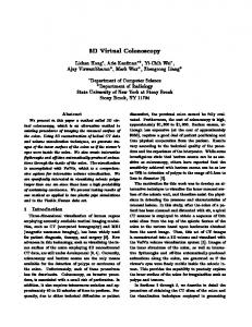
The goal of our work is to develop a method that will make it possible to create 3D maps that can be viewed in a collaborative virtual world, based on open data and open source technology, with the intent of maintaining the attribute data related to map objects. Unlike in professional applications, we aim to use data and tools that are available to anyone. In this work, Meshmoon [58] is used as an example of a collaborative virtual world platform based on open source code. Instead of using a model viewer application, and transferring the models, we use a client-server architecture offered by the virtual world platform. By this, the virtual world scene can be automatically kept up to date for all clients. Differently from most CAD applications, by using a multi-user virtual world, the users of the system can also communicate with each other over the system, and observe what other users are doing. We aim to develop a process where a virtual environment running in the Meshmoon system will be generated as automatically as possible from the open data sets provided by the NLS, using ALS data, orthophotos, and data from the topographic database. 2. Materials and Methods 2.1. The Meshmoon Platform Meshmoon is a virtual world platform developed based on the open-source realXtend Tundra technology [58]. In the platform, both the 3D models (meshes) and the applications used in the virtual world scene are downloaded as required from the server. The user can access the virtual world either by a dedicated client application or by using a web browser-based client [59]. As a realXtend-based system, Meshmoon utilizes the scene-entity-component-attribute model to describe the virtual world scene and its functionality. In this model, the components that describe individual features are assembled into entities describing the objects in the scene [60]. Figure 1 presents an example of a single entity having an attribute (id) that contains four components (name, mesh, placeable, dynamic), which in turn contain a number of attributes defining the name of the object, the URL for its mesh, and its position and orientation in the virtual world, among other things. The dynamic component can be used for storing freely defined attributes, such as additional data for entity.
Figure 1. Sample object composition using the scene-entity-component-attribute model.
ISPRS Int. J. Geo-Inf. 2015, 4
843
Unlike in most virtual world systems, none of the typical properties and functionalities of a virtual world, for example avatar, terrain, and sky, are “hardcoded” into the realXtend architecture. Even these basic object types are described using the same generic scene model. This enables a high degree of customizability for virtual worlds based on the realXtend technology. For example, it is possible to build scenes where users are not represented by avatars, but rather move with a free flying camera. In realXtend architecture, avatar is simply one application among others, that can either be used when creating the scenes, or not. This makes realXtend technology flexible, as it can be used to create networked 3D applications that are not limited by the typical elements of virtual worlds. RealXtend (and consequently Meshmoon) utilize the open-source 3D rendering engine OGRE3D [61]. The Open Asset Import Library is used to support a number of common 3D model file formats, making it possible to publish 3D content from different 3D modeling software tools [60]. With Meshmoon, the structure of the 3D virtual world scene is defined in a Tundra eXtensible Markup Language (TXML) file using the XML syntax. This file defines the entities and components of the virtual world and refers to the external files that are needed. The external data includes, for example, the mesh files that are retrieved based on the URL defined in the scene by using the HTTP protocol. 2.2. The Data Sets Used Several types of open data sets from the NLS were used. The data sets and their file formats are specified in Table 1 below. The topographic database includes all of Finland as a geographical area, and it contains items like the road networks, buildings, and administrative boundaries [62]. In the data, the roads and streets are described as center lines, with height information. For the buildings, there are outlines that are positioned at the height of the building footprint. It is available in 12 km × 12 km blocks in GML format [63]. In addition to the topographic database, true-color orthophotos, map rasters, and ALS point clouds were used. The orthophotos are available in 6 km × 6 km sheets, whereas the ALS point clouds are in 3 km × 3 km pieces. The NLS utilizes an orthogonal coordinate system based on the zone 35 of the Universal Transverse Mercator (UTM) projection. As Finland falls on three zones of UTM (34–36), the zone 35 has been extended to cover the entire country, thus forming TM35FIN [64]. Table 1. The data sets used. Data Set Orthophoto Map raster Topographic database ALS point cloud
Format jpg2000 tiff gml laz
3. Generating Virtual World Scenes Based on the National Land Survey Data The process of creating virtual world scenes from NLS open data was developed iteratively. To program the processing tools, we used the Python programming language [65]. As we wanted to create a virtual environment where additional data could be accurately added later on, we chose to use a coordinate system based on the TM35FIN in the virtual world. Thus, all of the objects in the virtual
ISPRS Int. J. Geo-Inf. 2015, 4
844
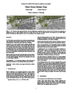
world can be returned to a real-world coordinate system, and vice-versa. To resolve some of the difficulties of using long coordinates, we defined a shifted coordinate system for the virtual world based on the, with the specified shift being −6,672,000 for the north axis and −378,500 for the east axis. Existing 3D modeling software can be used when creating city models [66]. As a proof of concept, we created the first versions of 3D virtual environments from open data by combining a 3D modeling suite, Blender 3D [67], and some automated processing. After this, the automated processing methods were developed. The development goal was to minimize manual processing, and to retain the object division of the original data. By using the same unique identifier numbers as in the topographic database, individual objects could be located based on their id. Thus, it would also be possible to replace individual objects with updated versions. In addition, we wanted to associate more data with the Meshmoon objects: Road pavement information (paved or unpaved), building classifications, and so forth. This information was written out to the virtual world scene file, as additional data components that were added to object entities. 3.1. Buildings To represent buildings, simple block models (Figure 2) were created using the building outlines of the topographic database. To make editing and updating the models simple, the building objects were separated: An individual building was represented as an individual mesh model and an independent entity in the virtual world. In the original data, the building geometry was defined in a global coordinate system, TM35FIN. Since we did not want the mesh models to use global coordinates, the models were generated with the mesh model located in its own coordinate system. The mesh model’s coordinate system used the first point of the building outline as the origin. The position of the mesh in the virtual world scene was then applied to position the mesh model. The building models were created by extruding the wall segments from the building outline. The height of the building was defined based on its height classification in the topographic database (1–3 with 3 reserved for chimneys, towers, etc.), resulting in two different building heights in the scene. The rendering material was chosen from two alternatives based on the height classification.
Figure 2. Single building model, with the original outline marked in orange, showing the height (h) and the origin (x,y,z) of the mesh model coordinate system.
ISPRS Int. J. Geo-Inf. 2015, 4
845
3.2. Roads The road objects were only described as polylines in the source data. Planar surfaces were created from them. Beginning with the starting and end points of an individual line segment: ), ( ,
=( ,
)
(1)
The line segment can also be described as a vector (v), with a perpendicular vector (vn) being: =(
) ,(
−
= −(
−
) ,(
−
)
(2)
−
)
) +(
−
(3)
The length of the perpendicular vector (vn) is then ln: = ||
|| =
(
−
) )
(4)
Based on the length (ln), we can then define the unit vector of the normal vector and multiply it by the desired width of the offset surface (d), forming the corner points (si, i = 1, ..., 4) of the plane, based on the original line segment (l) = =
1
− −
=
+
=
+
1
( −(
1 1
−
)
, )
−
+ ,
1 1
+
(
−
)
,
−
(
−
)
,
−
(
1 1
− (
)
(5) )
−
(6)
(
−
)
(7)
(
−
)
(8)
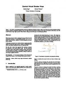
The object structure of the original data was preserved. The coordinates of the mesh model were defined using the same system as with the building models, taking the first point of each road object as its origin. The width and material of the road objects were defined based on the pavement class of the road objects in the topographic database (Figure 3).
Figure 3. Single road model containing several segments, with the original road line marked in orange, showing the width (d) and the origin of the mesh model coordinate system (x,y,z).
ISPRS Int. J. Geo-Inf. 2015, 4
846
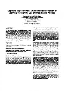
3.3. Terrain The terrain was represented as a 3D surface, using the using the terrain component of the Meshmoon platform. As the terrain component required a height map image as the source data, the height map was created by triangulating the classified ALS points to a Digital Elevation Model (DEM), and then rasterizing the DEM. The terrain object in Meshmoon was adjusted to match the scale of the other objects, using the elevation contours as a reference. The size of terrain was limited to 1.5 by 1.5 km, to ensure the performance of the resulting scene. To enhance the visual appearance of the terrain, two alternative textures were created for it using NLS open data. Both an aerial image and a map raster were used as a texture (Figure 4). The colors of the map raster were edited so that they could be adapted better to the scene lighting. The position and scale of the images were defined based on the known dimensions of the image areas in both cases. The images were cropped to accurately fit the terrain. In addition, 2D textured planar surfaces were added to the borders of the terrain, with a lighter colored map raster as texture.
Figure 4. The terrain with the building and road models textured using an aerial image (left) and an edited map raster (right). 3.4. Demonstration Application for Meshmoon Platform For demonstrating the application development potential in virtual worlds, a simple search and highlighting tool was developed. The tool allows the user to perform searches of objects, using the data included with them. The search filter can be used, for example, to search for certain types of buildings or locate a road with a specific name. Objects can also be queried with their id. When an object whose metadata contains the search filter is found, it is highlighted in the virtual world with an orange color, and the camera moved so that the found object or group of objects is at the center of view. The distance from camera to the objects is defined as the diagonal length of the bounding box containing all objects that matched the search criteria. Surrounding objects are not analyzed for collision or occlusion, as the tool was developed for use with a downward looking or oblique camera. Optionally, the tool can be used together with an avatar application to move the user’s avatar to the location being searched. As future work, the user might edit the metadata of the objects, allowing for two-way integration with existing GIS systems.
ISPRS Int. J. Geo-Inf. 2015, 4
847
4. Results By using a combination of 3D modeling and automated processing, three-dimensional, map-like virtual environments could be created for the Meshmoon platform. The method utilized as a proof of concept (Figure 5) still contained a number of problems. First, there were many manual steps involved in processing the data, especially with the building models. These manual steps were further complicated by long coordinates in the data, which were not supported by Blender’s user interface. The coordinate shift had to be applied manually before and after the editing phase, which made the process quite demanding and prone to error. In addition, the files that contained all of the building and road geometries were large in size and therefore slow to open and save. Since all objects of the same type were in the same file, editing, for example, an individual building required opening the entire file, manually editing the individual building, and then republishing the entire data set each time. Visually, there was also an issue with the objects, as the objects in the topographic database spanned a 12 km by 12 km area, whereas the terrain object (generated from ALS data) only spanned a 3 km by 3 km area. Meshmoon software was unable to reliably display more than one terrain tile at a time with satisfactory performance, so it would not have been possible to expand the terrain by adding more ALS tiles.
Figure 5. Buildings, roads, terrain, and contours in Meshmoon in an early, manually created version. By developing the processing methods further, it was possible to solve some of the issues faced when using a combination of automated processing and 3D modeling. The issue caused by different tile sizes of terrain and other objects was resolved by cropping everything to a 1.5 km by 1.5 km area. With the developed automated processing, the number of steps required to create a scene was considerably reduced: The scripts produce an output that can directly be uploaded to the server. Using the scripts, a virtual world scene can be created from any area in Finland for which ALS data are available. The generation and publishing of objects as well as setting up the scene was accomplished in a few hours, starting with downloading the data sets. The process of scene creation is presented in Figure 6. Since the
ISPRS Int. J. Geo-Inf. 2015, 4
848
buildings and roads are modeled as individual objects, the object count is quite high. The 1.5 km by 1.5 km sample area contains approximately 770 mesh objects, but less than 2 MB of mesh data, as the meshes are quite simple.
Figure 6. The process of scene creation. Automated steps are marked with green. The software implementations we have developed have been marked with an asterisk. Utilizing a 3D Map in a Virtual World In the virtual world scene, the user can move with a human-sized avatar or using a camera. A moveable downward-looking aerial camera (similar to most 3D map systems), or a free-flying camera (Figure 7) are both available. The compass application for Meshmoon can be used to make it easier to navigate in the scene, always showing the direction the camera is pointing at.
Figure 7. The Meshmoon scene can be navigated using an avatar, an aerial camera, or a free-flying camera. The building and road objects retain their object ids and object division of the original GML data. Object data from GML are also included, for example, building use and height classes, which are presented visually, and street names included as additional data in the road objects. The data can be viewed on an object-by-object basis or used to search for objects (Figure 8) using the application developed on the platform. For example, the distribution of residential buildings in the given area, or the location of a road with a specified name can be visualized by using the developed tool.
ISPRS Int. J. Geo-Inf. 2015, 4
849
Figure 8. On left: Searching all road objects where the name contains a given string. On right: Searching all buildings marked in the data as commercial-use buildings. The objects that were located are highlighted in orange. The content-creation tools of the Meshmoon platform can be used with the created scene. It is possible for users to move, scale, and delete existing building objects, to edit their data, or to create new objects using the existing mesh library (Figure 9). The mesh library contains a set of geometric primitives that can be added to the scene without using any external content production tools. By using these geometric primitives, the proposed building masses can be added to the 3D map, and refine their location and size iteratively. All of this work is carried out directly in the 3D environment. For example, these tools could be utilized to carry out the early stages of urban planning process. Since all data are on the server, changes made to the scene are immediately transferred to all other users online in the same scene, enabling collaboration.
Figure 9. User adding a block element, and moving a block element. Other 3D models can also be imported to the same environment. Figure 10 (left) shows an early design stage building model, which has been imported to the scene, and placed to its proposed location. The models can be explored with or without avatar. Figure 10 (right) shows a user in a two-display CAVE, adding a set of simple mesh objects to the scene. When placing mesh objects, the users preferred to move in the scene as avatar. For studying the model in overall view, an aerial camera was seen as more efficient, as moving long distances with the avatar was too time consuming. Inputting object coordinates
ISPRS Int. J. Geo-Inf. 2015, 4
850
directly was also possible, but required more effort from the user, as the scene operates in a shifted coordinate system, and no tools to automatically perform a reverse shift are provided by the platform.
Figure 10. Left: A building model imported into the scene. Right: User interacting with the model in a CAVE. 5. Discussion The creation of a virtual world scene was partially automated using the developed method. Building and road models were automatically created from the source data. In addition, the files containing their ids, positions, and any additional data were automatically written. The processing was performed separately for both object types. The resulting scene files had to be manually uploaded to the server, after which uploading the mesh models and assembling the final scene was done automatically. Automating these steps involved in the process would require a higher degree of integration with the platform’s back end. Currently, the conversion from GML is performed on a local machine by running a series of python scripts and publishing the scene using existing content production tools that are part of the Meshmoon system. The creation of the terrain object consisted of processing the ALS point cloud to a height map image, and then using a terrain component of the virtual world to create a 3D surface from the height map image. This processing chain should clearly be improved in the future. Triangulating a set of ALS points to be used as the 3D mesh representing the terrain would be the most direct solution. In conclusion, while some manual steps remain, it was possible to write automated scripts for most for the most labor-intensive tasks. Looking at the end result, the representation of buildings as simple block models is an acceptable solution in limited cases only. For more complex built entities, like churches, larger building complexes, water towers etc., the block models fail to sufficiently represent the original building. The use of ALS data to obtain roof geometries for the buildings would help enhance their visual quality and increase the level of detail. The limitation of only two different height classes in buildings also reduces the visual quality of the scene. Currently, a 20-storey office tower cannot be distinguished from a five-storey apartment building by the mesh models alone. This could be resolved by using a data set containing more detailed height information; for example, by calculating the correct building heights from ALS data. In addition, having only a single height definition for a building footprint is problematic if the building is located on a sloped surface. In these cases, the building outline should be extruded downwards as well to prevent a gap appearing between the building and the terrain.
ISPRS Int. J. Geo-Inf. 2015, 4
851
In an ideal situation, the used data set should have a terrain intersection curve for building objects. With this information, it would be possible to create the building models without this issue. The representation of roads as chains of simple planes is not problem free, either. Currently, the resulting road meshes have obvious gaps, when the consecutive segments are in angle. For best results, a data set containing the geometry of road edges should be used. The presented system utilizes a shifted, orthogonal coordinate system in the virtual world. As such, it can be used for any region from which suitable source data is available, by using a different coordinate shift. While this simplifies the processing, it also creates a set of problems. If the size of the virtual world scene is expanded, a geographic coordinate system using latitudes and longitudes should eventually be utilized. Currently, our method does not include any solutions to handling a scene with two differing coordinate systems. The performance of the platform limits the size of the area displayed. As a visualization tool, Meshmoon is inferior to existing visualization applications (e.g., see [68]). Additionally, the simplistic, not textured road and building models do not fully utilize the rendering potential offered by the platform. The road objects, and roofs could be textured using an orthophoto, but for texturing the building facades, either oblique aerial images, or terrestrial images would be required. If a more complex model of the environment would be used, such as illustrated by [16], the sense of immersion offered by the platform would be stronger. Having photo textures in buildings would also help to identify them. However, as the experience of developing small applications utilizing the data, and the potential for collaborative interaction with the model illustrate, there are some benefits to using an existing virtual world system, especially as it permits application development. In addition, display devices like CAVE or OculusRift can easily be used, as they are readily supported by the platform. In the presented case, all processing methods were specifically developed for the data sets offered by NLS as open data, and using a shifted coordinate system adapted for Southern Finland. As such, they are not directly transferrable to other countries. However, a different coordinate shift and set of tags in GML could be used to create similar virtual world scenes from other regions, if suitable source data is available. The emergence of standardized city model format, CityGML [69] reduces the difficulties of developing area-specific processing workflows, and paves the way for more widely applicable virtual world generation methods. For building virtual worlds, there are other platforms besides Meshmoon, for example [70,71]. Commercial hosting is available at least for [71]. The automated generation of simple 3D city models containing building and road objects from Open Street Map data has been implemented by Vizicities [72], and can also be found from older GIS literature [18]. However, the combination of multi user virtual worlds and large map like scenes is less common. Meshmoon Geo [73], a commercial tool based on realXtend technology and the Meshmoon platform was released by Adminotech in February 2015, employing the data from OSM and the city of Espoo. The scene (Figure 11) is generated automatically from GIS data. In this case, a dataset containing accurate building heights is used. However, instead of a DEM, a flat terrain is used. The data from city is obtained directly from the GIS server via a WFS/WMS interface. Video conferencing tools can be used in the scene. Currently, we have been unable to verify the ability of other existing virtual world platforms to support large, map like scenes.
ISPRS Int. J. Geo-Inf. 2015, 4
852
Figure 11. A Meshmoon Geo scene. 6. Conclusions The paper demonstrated methods that enable the creation of 3D maps for a collaborative, up-to-date virtual world based on open source technology, from open data, while maintaining the attribute data related to the objects. The generation of a virtual world scene from NLS data was partially automated. The work was implemented in Meshmoon virtual environment. Its ability to support existing 3D mesh formats was a significant enabling factor when developing the automated processing methods. As the client-server architecture of Meshmoon permits synchronized editing of world entities by users, it is possible to collaboratively edit the map data in the scene and, thus, keeping the maps updated also by crowdsourcing. Improving the open data maps with collaborative mapping is one of the potential strengths of the platform. For more efficient editing, and content creation in the scene, the content creation tools of the platform should be improved. Currently, the tools do not function fluently with an aerial camera, but are best suited for working with avatar. The application development possibility in virtual worlds is a significant new development direction with geographic data. It has great potential in areas like 3D data visualization [30], urban planning [74,75], gaming [76], or disaster management [77]. As more GIS data are released as open data, we can expect that more applications utilizing such data will be developed, both by GIS professionals and by developers coming from other disciplines. To stimulate development, the data should be released in a format that easily permits the utilization of data for a variety of applications. The development of automatic processing methods that permit the use of open data-based 3D maps in virtual environments is a prerequisite for such applications. Acknowledgments This research was supported by the Academy of Finland, the Centre of Excellence in Laser Scanning Research (CoE-LaSR, project number 272195), the Finnish Funding Agency for Innovation (Tekes) ÄRY project, the Aalto Energy Efficiency Research Programme (Light Energy—Efficient and Safe Traffic Environments project), Research on Resident-Driven Infill Development Possibilities—Case Study in Urban Areas in Finland (REPSU), the Aalto University doctoral program and the EUE project (project
ISPRS Int. J. Geo-Inf. 2015, 4
853
number 2141226). The authors wish to thank SRV and SARC Architects Ltd. for the building model used in experiments. Author Contributions Juho-Pekka Virtanen was the main author of the article and he developed the processing methods. Ali Kämäräinen developed the search and highlight application for Meshmoon. The article was improved by the contributions of all the co-authors at various stages of the analysis and writing process. Conflicts of Interest The authors declare no conflict of interest. References 1.
Laakso, K.; Gjesdal, O.; Sulebak, J.S. Tourist information and navigation support by using 3D maps displayed on mobile devices. In Proceedings of the Workshop HCI in Mobile Guides, Udine, Italy, 8 September 2003. 2. Batty, M.; Hudson-Smith, A.; Milton, R.; Crooks, A. Map mashups, Web 2.0 and the GIS revolution. Ann. GIS 2010, 16, 1–13. 3. Döllner, J.; Kolbe, T.H.; Liecke, F.; Sgouros, T.; Teichmann, K. The virtual 3D city model of berlin-managing, integrating, and communicating complex urban information. In Proceedings of the 25th Urban Data Management Symposium UDMS, Aalborg, Denmark, 15–17 May 2006. 4. Nurminen, A.; Oulasvirta, A. Designing interactions for navigation in 3D mobile maps. In Map-Based Mobile Services: Design, Interaction and Usability; Meng, L., Zipf, A., Winter, S., Eds.; Springer: London, UK, 2008; pp. 198–224. 5. Vainio, T.; Kotala, O. Developing 3D information systems for mobile users: Some usability issues. In Proceedings of The Second Nordic Conference on Human-Computer Interaction, Aarhus, Denmark, 19–23 October 2002; pp. 231–234. 6. Batty, M.; Chapman, D.; Evans, S.; Haklay, M.; Kueppers, S.; Shiode, N.; Smith, A.; Torrens, P.M. Visualizing the city: Communicating urban design to planners and decision-makers. In CASA Working Papers; University College London: London, UK, 2000. 7. Google Earth. Available online: http://www.google.com/earth/ (accessed on 2 April 2015). 8. 3D Mapping & 3D Modeling Market Worth $7.7 Billion by 2018. Available online: http://www.marketsandmarkets.com/PressReleases/3d-mapping.asp (accessed on 8 December 2014). 9. Vosselman, G.V., Maas, H.G., Eds. Airborne and Terrestrial Laser Scanning; Whittles: Caithness, UK, 2010. 10. Baltsavias, E.P.; Pateraki, M.; Zhang, L. Radiometric and geometric evaluation of IKONOS geo images and their use for 3D building modeling. In Proceedings of the Joint ISPRS Workshop on High Resolution Mapping from Space 2001, Hannover, Germany, 19–21 September. 11. Brenner, C. Building reconstruction from images and laser scanning. Int. J. Appl. Earth Observ. Geoinf. 2005, 6, 187–198.
ISPRS Int. J. Geo-Inf. 2015, 4
854
12. Haala, N.; Kada, M. An update on automatic 3D building reconstruction. ISPRS J. Photogram. Remote Sens. 2010, 65, 570–580. 13. Kaartinen, H.; Hyyppä, J. EuroSDR-Project Commission 3 “Evaluation of Building Extraction”, Final Report. In EuroSDR—European Spatial Data Research; Official Publication No 50; EuroSDR (European Spatial Data Research): Dublin, Ireland, 2006; pp. 9–77. 14. Remondino, F.; El-Hakim, S. Image-based 3D modelling: A review. Photogram. Rec. 2006, 21, 269–291. 15. Kukko, A.; Kaartinen, H.; Hyyppä, J.; Chen, Y. Multiplatform mobile laser scanning: Usability and performance. Sensors 2012, 12, 11712–11733. 16. Zhu, L.; Hyyppä, J.; Kukko, A.; Kaartinen, H.; Chen, R. Photorealistic building reconstruction from mobile laser scanning data. Remote Sens. 2011, 3, 1406–1426. 17. Zhu, L.; Hyyppä, J. The use of airborne and mobile laser scanning for modeling railway environments in 3D. Remote Sens. 2014, 6, 3075–3100. 18. Verbree, E.; Maren, G.V.; Germs, R.; Jansen, F.; Kraak, M.J. Interaction in virtual world views-linking 3D GIS with VR. Int. J. Geogr. Inf. Sci. 1999, 13, 385–396. 19. Doyle, S.; Dodge, M.; Smith, A. The potential of web-based mapping and virtual reality technologies for modelling urban environments. Comput. Environ. Urban Syst. 1998, 22, 137–155. 20. Döllner, J.; Baumann, K.; Buchholz, H. Virtual 3D city models as foundation of complex urban information spaces. In Proceedings of the CORP 2006, Vienna, Austria, 13–16 February 2006. 21. Döllner, J.; Walther, M. Real-time expressive rendering of city models. In Proceedings of the Seventh International Conference on Information Visualization, London, UK, 16–18 July 2003; pp. 245–252. 22. Mazuryk, T.; Gervautz, M. Virtual Reality-History, Applications, Technology and Future; Vienna University of Technology: Vienna, Austria, 1996. 23. Kraak, M.-J.; Smets, G.; Sidjanin, P. Virtual reality, the new 3-D interface for geographical information systems. In Spatial Multimedia and Virtual Reality; Camara, A.S., Raper, J., Eds.; Taylor & Francis: London, UK, 1999; pp. 131–136. 24. Unity 3D, Create the Games You Love with Unity. Available online: http://unity3d.com/unity (accessed on 5 January 2015). 25. Germanchis, T.; Pettit, C.; Cartwright, W. Building a three-dimensional geospatial virtual environment on computer gaming technology. J. Spat. Sci. 2004, 49, 89–95. 26. Stock, C.; Bishop, I.D.; O’Connor, A. Generating virtual environments by linking spatial data processing with a gaming engine. In Proceedings of the 6th International Conference for Information Technologies in Landscape Architecture, Dessau, Germany, 26–28 May 2005. 27. Manyoky, M.; Wissen Hayek, U.; Heutschi, K.; Pieren, R.; Grêt-Regamey, A. Developing a GIS-based visual-acoustic 3D simulation for wind farm assessment. ISPRS Int. J. Geo-Inf. 2014, 3, 29–48. 28. Dodge, M.; Doyle, S.; Hudson-Smith, A.; Fleetwood, S. Towards the virtual city: VR & internet GIS for urban planning. In Proceedings of Virtual Reality and Geographical Information Systems Workshop, London, UK, 22 May 1998.
ISPRS Int. J. Geo-Inf. 2015, 4
855
29. Steinicke, F.; Ropinski, T.; Hinrichs, K.; Mensmann, J. Urban city planning in semi-immersive virtual reality systems. In Proceedings of the First International Conference on Computer Graphics Theory and Applications, Setúbal, Portugal, 25–28 February 2006; pp. 192–199. 30. Huang, B.; Jiang, B.; Li, H. An integration of GIS, virtual reality and the Internet for visualization, analysis and exploration of spatial data. Int. J. Geogr. Inf. Sci. 2001, 15, 439–456. 31. Ishida, T.; Akahani, J.; Hiramatsu, K.; Isbister, K.; Lisowski, S.; Nakanishi, H.; Okamoto, M.; Miyazaki, Y.; Tsutsuguchi, K. Digital city Kyoto: Towards a social information infrastructure. In Proceedings of the 3rd International Conference on Cooperative Information Agents III (CIA’99), Uppsala, Sweden, 31 July–2 August 1999; pp. 34–46. 32. Videira Lopes, C.; Lindstrom, C. Virtual cities in urban planning: The Uppsala case study. J. Theor. Appl. Electron. Commer. Res. 2012, 7, 88–100. 33. About Open Data. Available online: http://www.hri.fi/en/open-data/ (accessed on 23 January 2015) 34. Over, M.; Schilling, A.; Neubauer, S.; Zipf, A. Generating web-based 3D City Models from OpenStreetMap: The current situation in Germany. Comput. Environ. Urban Syst. 2010, 34, 496–507. 35. ViziCities. Available online: https://github.com/robhawkes/vizicities (accessed on 20 February 2014). 36. ShareGeo Open. Available online: http://www.sharegeo.ac.uk/docs/about.pdf (accessed on 8 December 2014). 37. PKOD. Available online: https://www.pdok.nl/en (accessed on 8 December 2014). 38. Poikola, A.; Kola, P.; Hintikka, K.A. Julkinen Data—Johdatus Tietovarantojen Avaamiseen; Liikenne- ja Viestintäministeriö: Helsinki, Finland, 2010; p. 94. (In Finnish) 39. Bria, F. New governance models towards a open Internet ecosystem for smart connected European cities and regions. In Open Innovation 2012; European Union: Luxembourg, 2012. 40. Instructions for Participation. Available online: http://www.apps4finland.fi/instructions-forparticipation/ (accessed on 20 February 2014). 41. Opendata.fi. Available online: https://www.opendata.fi/en (accessed on 20 November 2014). 42. What Does Availability Signify? Available online: http://www.maanmittauslaitos.fi/en/opendata/ what-does-availability-signify (accessed on 20 February 2014). 43. Laser Scanning Data. Available online: http://www.maanmittauslaitos.fi/en/digituotteet/ laser-scanning-data (accessed on 10 February 2015). 44. Hollands, R.G. Will the real smart city please stand up? Intelligent, progressive or entrepreneurial? City 2008, 12, 303–320. 45. Su, K.; Li, J.; Fu, H. Smart city and the applications. In Proceedings of the International Conference on Electronics, Communications and Control (ICECC), Ningbo, China, 9–11 September 2011; pp. 1028–1031. 46. Schaffers, H.; Komninos, N.; Pallot, M.; Trousse, B.; Nilsson, M.; Oliveira, A. Smart cities and the future internet: towards cooperation frameworks for open innovation. In The Future Internet; Springer: Berlin, Heidelberg, Germany, 2011; pp. 431–446. 47. Prandi, F.; Soave, M.; Dev, F.; Andreolli, M.; de Amicis, R. Services oriented smart city platform based on 3D city model visualization. ISPRS Ann. Photogramm. Remote Sens. Spat. Inf. Sci. 2014, doi:10.5194/isprsannals-II-4-59-2014.
ISPRS Int. J. Geo-Inf. 2015, 4
856
48. Lee, S.; Yigitcanlar, T.; Han, J.; Leem, Y. Ubiquitous urban infrastructure: Infrastructure planning and development in Korea. Innov.: Manag. Policy Pract. 2008, 10, 282–292. 49. Lopes, C.; Kan, L.; Popov, A.; Morla, R. PRT Simulation in an Immersive Virtual World. In Proceedings of the First International Conference on Simulation Tools and Techniques for Communications, Marseilles, France, 3–7 March 2008, pp. 1–7. 50. Messinger, P.; Stroulia, E.; Lyons, K. A typology of virtual worlds: Historical overview and future directions. J. Virtual Worlds Res. 2008, doi:10.4101/jvwr.v1i1.291. 51. Lopes, C. The massification and webification of systems’ modeling and simulation with virtual worlds. In Proceedings of the 7th joint meeting of the European Software Engineering Conference (ESEC) and the ACM SIGSOFT Symposium on the Foundations of Software Engineering (FSE), Amsterdam, The Netherlands, 24–28 August 2009; pp. 63–70. 52. Hew, K.F.; Cheung, W.S. Use of three-dimensional (3-D) immersive virtual worlds in K-12 and higher education settings: A review of the research. Br. J. Educ. Technol. 2010, 41, 33–55. 53. Tapiola 3D. Available online: http://vrs3d.sito.fi/Demos/Tapiola.html (accessed on 23 January 2015). 54. Rodrigues, J.I.; Figueiredo, M.J.; Costa, C.P. Web3DGIS for city models with CityGML and X3D. In Proceedings of the 17th International Conference in Information Visualisation, London, UK, 15–18 July 2013; pp. 384–388. 55. Wu, H.; He, Z.; Gong, J. A virtual globe-based 3D visualization and interactive framework for public participation in urban planning processes. Comput. Environ. Urban Syst. 2010, 34, 291–298. 56. Heipke, C. Crowdsourcing geospatial data. ISPRS J. Photogramm. Remote Sens. 2010, 65, 550–557. 57. Fritz, S.; McCallum, I.; Schill, C.; Perger, C.; Grillmayer, R.; Achard, F.; Kraxner, F.; Obersteiner, M. Geo-Wiki. Org: The use of crowdsourcing to improve global land cover. Remote Sens. 2009, 1, 345–354. 58. What is Meshmoon. Available online: http://meshmoon.com/About.aspx (accessed on 23 January 2015). 59. Meshmoon WebRocket. Available online: http://meshmoon.com/WebRocket.aspx (accessed on 23 January 2015). 60. Alatalo, T. An entity-component model for extensible virtual worlds. Internet Comput. 2011, 15, 30–37. 61. About, Ogre. Available online: http://www.ogre3d.org/about (accessed on 23 January 2015). 62. The Topographic Database. Available online: http://www.maanmittauslaitos.fi/en/digituotteet/ topographic-database (accessed on 23 January 2015). 63. Geography Markup Language. Available online: http://www.opengeospatial.org/standards/gml (accessed on 23 January 2015). 64. Ollikainen, M.; Ollikainen, M. The Finnish Coordinate Reference Systems. Available online: http://www.maanmittauslaitos.fi/sites/default/files/Finnish_Coordinate_Systems.pdf (accessed on 12 May 2015). 65. Python. Available online: https://www.python.org/about/ (accessed on 20 January 2015). 66. Sahin, C.; Alkis, A.; Ergun, B.; Kulur, S.; Batuk, F.; Kilic, A. Producing 3D city model with the combined photogrammetric and laser scanner data in the example of Taksim Cumhuriyet square. Opt. Lasers Eng. 2012, 50, 1844–1853. 67. Blender. Available online: http://www.blender.org/ (accessed on 20 January 2015).
ISPRS Int. J. Geo-Inf. 2015, 4
857
68. Jobst, M.; Döllner, J. 3D city model visualization with cartography-oriented design. In Proceedings of the REAL CORP 008, Vienna, Austria, 19–21 May 2008; pp. 507–515. 69. Gröger, G.; Plümer, L. CityGML-interoperable semantic 3D city models. ISPRS J. Photogramm. Remote Sens. 2012, 71, 12–33. 70. Openwonderland. Available online: http://openwonderland.org/ (accessed on 31 March 2015). 71. OpenSimulator. Available online: http://opensimulator.org (accessed on 31 March 2015). 72. ViziCities. Available online: http://vizicities.com/ (accessed on 31 March 2015). 73. Meshmoon Geo Espoo. Available online: http://espoo-wfs.meshmoon.com/ (accessed on 2 April 2015). 74. Drettakis, G.; Roussou, M.; Reche, A.; Tsingos, N. Design and evaluation of a real-world virtual environment for architecture and urban planning. Presence: Teleoperators Virtual Environ. 2007, 16, 318–332. 75. Hyyppä, H.; Virtanen, J.-P.; Ahlavuo, M.; Hollström, T.; Hyyppä, J.; Zhu, L. Regional information modeling and virtual reality tools. In Orchestrating Regional Innovation Ecosystems Espoo Innovation Garden; Lappalainen, P., Markkula, M., Kune, M., Eds.; Aalto University: Espoo, Finland, 2015. 76. Cities: Skylines. Available online: http://store.steampowered.com/app/255710/ (accessed on 2 April 2015). 77. Ahlavuo, M.; Hyyppä, H.; Hyyppä, J.; Holopainen, M.; Vastaranta, M.; Virtanen, J.-P.; Alho, P. Tarkat paikkatietomenetelmät parantavat ilmastonmuutoksen aiheuttamien luonnonvarariskien hallintaa. (Accurate location based methods for improving management of risks caused by climate change). In Yhteistä Tulevaisuutta Rakentamassa ja Kartoittamassa; Hyyppä, H., Ahlavuo, M., Eds.; Helsinki Metropolia University of Applied Sciences: Helsinki, Finland, 2014; pp. 55–64. (In Finnish) © 2015 by the authors; licensee MDPI, Basel, Switzerland. This article is an open access article distributed under the terms and conditions of the Creative Commons Attribution license (http://creativecommons.org/licenses/by/4.0/).