In Proceedings of the 2010 International Conference on Computer Design
Inter-socket Victim Cacheing for Platform Power Reduction Subhra Mazumdar University of California, San Diego
[email protected]
Dean M. Tullsen University of California, San Diego
[email protected]
Abstract— On a multi-socket architecture with load below peak, as is often the case in a server installation, it is common to consolidate load onto fewer sockets to save processor power. However, this can increase main memory power consumption due to the decreased total cache space. This paper describes inter-socket victim cacheing, a technique that enables such a system to do both load consolidation and cache aggregation at the same time. It uses the last level cache of an idle processor in a connected socket as a victim cache, holding evicted data from the active processor. This enables expensive main memory accesses to be replaced by cheaper cache hits. This work examines both static and dynamic victim cache management policies. Energy savings is as high as 32.5%, and averages 5.8%.
I. I NTRODUCTION Current high-performance processor architectures commonly feature four or more cores on a single processor die, with multiple levels of the cache hierarchy on-chip, sometimes private per core, sometimes shared. Typically, however, all cores share a large last level cache (LLC) to minimize the data traffic that must go off chip. Servers typically replicate this architecture with multiple interconnected chips, or sockets. These systems are often configured to handle some expected peak load, but spend the majority of the time at a load level below that peak. Barroso and H¨olzle [1] show that servers operate most of the time between 10 and 50 percent of maximum utilization. Unfortunately this common operating mode corresponds to the lowest energy efficient region. Virtualization and consolidation techniques often migrate workloads to a few active sockets while putting the others in a low power mode to save energy. However, consolidation typically increases the last level cache miss rate [2] and (as a result) main memory power consumption, due to decreased total cache space. This paper seeks to achieve energy efficiency at those times by using the LLCs of idle sockets to reduce the energy consumption of the system, thus enabling both core consolidation and cache aggregation at the same time. While many energy-saving techniques employed in this situation (consolidation, lowpower memory states, DVFS, etc.) trade off performance for energy, this architecture saves energy while improving performance in most cases. We propose small changes to the memory controllers of modern multicore processors that allow them to use the LLC of a neighboring socket as a victim cache. When successful, a read from the LLC of a connected chip completes with lower latency and consumes less power than a DRAM access. This is due to the high-bandwidth point-to-point interconnect available between sockets, for example, Intel’s Quick Path Interconnect (QPI) or AMD’s Hyper Transport (HTT). By
Justin Song Intel Corporation
[email protected]
doing this, unused cores need no longer be an energy liability. Not only are they available for performance boost in times of heavy load, but now they can also be used to reduce energy consumption in periods of light load. Reducing memory traffic has a 2-fold impact on power consumption. We save costly accesses to DRAM, but also allow the system to put memory into low-power states more often. To enable victim cacheing on another socket, the intersocket communication protocol must be extended with extra commands that will move the evicted lines from the local socket to the remote socket. Future server platforms are expected to have 4 to 32 tightly connected sockets with large on-chip caches per socket. To show the effectiveness of this policy, we use a dual socket configuration in which one of the sockets is active, running some workload, while the other socket is in an idle state. This assumes we can power the LLC without unnecessarily powering the attached cores, which is possible in newer processors. For example, the Intel Nehalem processors have the LLC on a different uncore voltage/frequency domain, thus enabling the cores to be powered off while the uncore is active. We show two different policies for maintaining a crosssocket victim cache. The first is a static victim cache policy, where the idle socket LLC is always on and used as a victim cache by the active socket. This policy shows improvement in energy for many benchmarks, but consumes more energy for some others. When the victim cache is not effective, we add extra messages and an extra cache access to the latency and energy of the original DRAM access. Therefore, we also demonstrate a dynamic policy to filter out the benchmarks that are not using the victim cache effectively. In this case, the memory controller dynamically decides whether to switch on the victim cache and use it based on simple heuristics. The latter policy sacrifices little of the energy gains where the victim cache is working well, but significantly reduces the energy loss in the other cases. The rest of the paper is organized as follows. Section II provides an overview of the related work. Section III explains the cache and DRAM power models and the dynamic policy to control the victim cache. Section IV describes the experimental methodology and results. Section V concludes. II. R ELATED W ORK This work strives to exploit the integration of different levels of the cache/memory hierarchy as they exist in current architectures. Most previous work on power and energy management techniques focus on a particular system component. Lebeck, et al. [3] propose power-aware page allocation
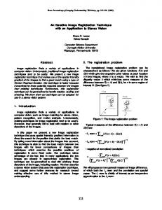
algorithms for DRAM power management. Using support from the memory controller for fine-grained bank level power control, they show increased opportunities for placing the memory in the low power mode. Delaluz, et al. [4] and Huang, et al. [5] propose OS level approaches which maintain page tables that map processes to the memory banks with allocated memory. This allows the OS to dynamically switch off unutilized banks. Recent studies [1] show that in modern systems, the CPU is no longer the primary energy consumer. Main memory has become a significant consumer, contributing 30-40% of the total energy on modern server systems. Hence the trade off between power consumption of the different components of a system is key to achieving optimum balance. Using the caches of idle cores to reduce the number of main memory accesses presents this opportunity. Several research works seek to exploit victim cacheing to improve CPU performance by holding evicted data for future access. Jouppi [6] originally proposed the victim cache as a small, associative buffer that captures evicted data from a direct-mapped L1 cache. Chang and Sohi [7] propose using the unused cache of other on-chip cores to store globally active data, which they refer to as aggregate cache. This reduces the number of off-chip requests through cache-tocache data transfers. Feeley, et al. [8] use the concept of victim cacheing to keep active pages in the memory of remote nodes in an internetwork, instead of evicting them to the disk. Leveraging such network-wide global memory improves both performance and energy efficiency. Kim, et al. [9] propose an adaptive block management scheme for a victim cache to reduce the number of accesses to more power-consuming memory structures such as L2 caches. They use the victim cache efficiently by selecting the blocks to be loaded into it based on L1 history information. Memik, et al. [10] attack the same problem with modified victim cache structures and miss prediction to selectively bypass the victim cache access, thus avoiding energy waste for data search in the victim cache. This paper proposes the use of existing cache capacity offchip to significantly reduce the energy consumption of main memory. III. D ESIGN This section provides some background material on DRAM design and introduces our inter-socket victim cache architecture. A. DRAM functionality Background The effectiveness of trading off-chip LLC accesses for DRAM accesses depends on the complex interplay between levels of the memory hierarchy, the communication links, etc. In this section, we discuss our model of DRAM access, as we have found that it is critical to accurately model the complex power states of these components over time in order to reach the right conclusions and properly evaluate tradeoffs. DRAM is generally organized as a hierarchy of ranks, with each rank made up of multiple chips, each with a certain data
Rank 2
Rank 1
Rank 3
Rank 4
DDR SDRAM Controller DRAM Chips
Address & cmd Data bus Chip (DIMM) Select
Fig. 1. Clk CKE Cmd
DRAM organized as ranks.
Control Logic Row Addr Decoder
Row Addr v
Mux
Bank Memory Array
Addr Register
Bank Control Logic
M U X
Row Buffer
I/O Gating
Addr
Read Latch
Column decoder
64 Input Regs
D0-D7
Write Driver
Column Addr Decode
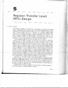
Fig. 2.
A single DRAM chip.
output width as shown in Figure 1. Each chip is internally organized as multiple banks with a sense amplifier or row buffer for each bank, as shown in Figure 2. Data from an entire row of a bank can be read from the memory array into the row buffer and then bytes can be read from or written to the row buffer. For example, a 4GB DRAM can be organized as 4 ranks, each 1GB in capacity and organized as eight 1Gb memory chips. To deliver a cache line, only one rank need be active and every chip in that rank will deliver 64 bits (64 bits will be delivered in transfers of 8 bits) in parallel thus forming a 64 Byte cache line in four cycles (dual data rate). There are four basic DRAM commands that are used: ACT, READ, WRITE and PRE. The ACT command is used to load data from a row of a device bank into the row buffer. READ and WRITE commands can be used to perform the actual reads and writes of the data once in the row buffer. Finally a PRE command is used to store the row back to the array. A PRE command needs to be used for every ACT command since the ACT discharges the data in the array. The above commands can only be applied when the clock enable (CKE) of the chip is high. If the CKE is high it is said to be in standby mode (STBY); otherwise, it is in power
transition
transition
ACT_STBY (active)
ACT_STBY (active)
Power increases timeout
PRE_STBY
PRE_STBY
PRE_PDN (power-down)
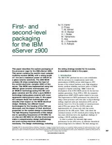
Fig. 3.
DRAM power states.
down mode (PDN). Also if any of the banks in a device are open (i.e. data is present in the row buffer) it is said to be in active state (ACT). If all the banks are pre-charged, it is in the pre-charged state (PRE). Thus the DRAM can be in one of the following combination of states: ACT STBY, PRE STBY, ACT PDN and PRE PDN. We assume a memory transaction transitions through 3 states only. First, CKE is made high and data is loaded from the memory array to the row buffer. At this time the device is in ACT STBY state. After completion of the read/write the row is precharged and the bank is closed, with the device going into the PRE STBY state. Finally if no further request comes, after a timeout period the CKE is lowered and the device enters the PRE PDN state. In a multi-rank module, ranks are often driven with the same CKE signal, thus requiring all other ranks to be in standby mode while one rank is active. The state transitions of the DRAM device are shown in Figure 3. We assume a closed page policy which is essentially a fast exit from ACT STBY to PRE STBY for both our baseline and victim cache architecture. Memory controller policies for DRAM power management [11] show that this simple policy of immediately transitioning the DRAM chip to a lower power state performs better than sophisticated policies. B. Inter-Socket Victim Cache Architecture We examine two management policies, a static policy that always uses the victim cache, if available, and another that may ignore the victim cache when the application does not benefit. a) Static Policy: In multi-socket systems, the sockets are generally interconnected through point-to-point links, which have low delay and high bandwidth, such as Intel’s Quick Path Interconnect (QPI) or AMD’s Hyper Transport (HTT). These links maintain cache coherence across sockets by sending snoop traffic, invalidation requests, and cache-tocache data transfers. To enable victim cacheing, we need to make only minor changes to the memory controller and the transport protocol. The inter-socket communication protocol needs to be extended with extra commands that will send the address of a cache line to search in the remote cache and also store evicted data from the local socket to the remote socket. No extra logic overhead is incurred since such requests already exist as part of the snooping coherence protocol. These transfers
can be fast, as the links typically support high bandwidth, for example up to 25GB/s on Intel’s Nehalem processors. The memory controller only has to be aware of whether we are in victim cache mode, and which socket or sockets can be used. We assume the OS saves this information in a special register. In a multi-socket platform, any idle socket can be chosen by an active socket to evict its data, but we’d prefer one which is directly connected. With our victim cache policy, on a local LLC miss data is searched in the remote socket LLC by sending the address over the inter-socket link. If the cache line is found, the data is sent to and stored in the local socket cache. At the same time, the LRU cache line from the local cache is evicted to replace the line being read from the victim cache – resulting in a swap between the two caches. In case of a miss in the victim cache, data needs to be brought from main memory. The cache line evicted from the local LLC is written back to the victim LLC. This may cause an eviction of a dirty line from the victim LLC which will be written back to main memory. It is important to note that we assume the DRAM access is serialized with the remote socket snoop. When the memory controller is in normal coherence mode, it is common practice to do both the snoop and initiate the DRAM access in parallel for performance reasons. Thus, the memory controller follows a slightly different (serial) access pattern when we are in victim cache mode. Accessing the remote cache and DRAM in parallel makes sense when the likelihood of a snoop hit is assumed to be low. However, when the victim cache is enabled, we expect the frequency of remote hits to be much higher, making serial access significantly more energy efficient. The result of this policy is that we increase DRAM latency in the case of a victim cache miss. Therefore, an application that gets no benefit at all from the victim cache will likely see an overall decrease in performance, as well as a loss of energy (both due to the increased runtime and the extra, ineffective remote LLC accesses). For this reason we also examine a dynamic policy that attempts to identify workloads or workload phases for which the victim cache is ineffective. b) Dynamic Policy: Not all applications will take advantage of the victim cache. For example, streaming applications which touch large amounts of data with little reuse will not see many hits in the victim cache. For those applications our architecture can have an adverse effect on energy efficiency. To counter this, we propose a dynamic cache policy which can intelligently turn on the victim cache and use it when profitable, while switching it off otherwise. We want to minimize changes and additions to the memory controller, so we seek to do this with simple heuristics based on easily-gathered data. We assume that the memory controller is able to keep count of the number of hits in the victim cache over some time period. This is easily implemented by using a counter which can be incremented by the controller every time there is a victim hit. The memory controller samples the victim cache policy in a small time window by switching it on (if it is not already).
At the end of the interval, it compares the counter with a threshold (threshold hit). If the number of victim hits is equal to or below threshold hit, the victim cache is turned off until the next sampling interval, otherwise it is kept on. We continue to sample at regular intervals to dynamically adapt to application phases. The threshold hit value can be stored in a register and set by the controller. In this way, the threshold can be changed based on operating conditions that the OS might be aware of (load, time-varying power rates, etc.) – we assume a single threshold. When sampled behavior is near threshold, oscillating between on and off can be expensive, especially due to the extra writebacks of dirty data in the victim cache to memory. Therefore, we also account for the cost of turning the victim cache off by tracking the number of dirty lines in the victim cache. If this is more than threshold dirty at the end of the sampling interval, we leave the victim cache on. This does not mean the victim cache stays on forever once it acquires dirty data, even in the presence of unfriendly access patterns – for example, a streaming read will clear the cache of dirty data and allow it to be turned off. The count of dirty lines is not just an indicator of the cost of switching, but also a second indicator of the utility of the victim cache. This is because eviction of dirty lines to the victim cache saves more energy than eviction of clean lines. This is for two reasons: (1) memory writes take more power, and (2) the eviction (read and transfer the line from the local LLC) would have been necessary even without the victim cache if the line was dirty. Therefore, we switch the victim cache off only if both these conditions fail. This policy makes the controller more stable and reduces the energy wasted due to frequent bursts of write-backs. Hardware counters similar to those mentioned above are already common in commercial processors. IV. E VALUATION In this section we describe the cache and memory simulator used for evaluating our policy and give the results of those simulations. Detailed simulation of core pipelines is not necessary since we are only interested in cache and memory power tradeoffs. A. Methodology For our experimental evaluation we use a cycle accurate memory trace based simulator that models the power and delay for the last level cache, the victim cache, and main memory. The memory traces are obtained using the SMTSIM [12] simulator with the timing (clock cycle), address, and read/write information. The timing data is used to establish inter-arrival times for memory accesses from the same thread. The traces are used as input to our cachememory simulator, which reports the total energy, miss ratio, DRAM state residencies and other statistics. The L2 cache is modeled as private with a capacity of 256 KB per core. We do not capture the L1 cache traces since we assume an inclusive cache hierarchy – data access requests filtered by
TABLE I L AST LEVEL CACHE (L3) CHARACTERISTICS (8MB) Parameter Dynamic read energy Dynamic write energy Static leakage power Read access latency Write access latency
Value 0.67 nJ 0.60 nJ 154 mW 8.2 ns 8.2 ns
TABLE II DRAM CHARACTERISTICS (1G B CHIP ) Parameter Active + Precharge energy Read power Write power ACT STBY power PRE STBY power PRE PDN power Self-refresh power Read latency (from row buffer) Write latency (to row buffer)
Value 3.18 nJ 228 mW 260 mW 118 mW 102 mW 39 mW 4 mW 15 ns 15 ns
the L2 cache will be the same in both cases as seen by the LLC. Delay and power for the cache sub-system is modeled using CACTI [13]. The last level cache (the L3 cache) has 8MB capacity with 16 ways and organized into 4 banks, based on 45nm technology. The cache line is 64 Bytes. Table I shows the delays, dynamic energy per access, and the static leakage power consumed by the cache. All these configurations are based on the Intel Nehalem processor used on dual socket server platforms. The main memory is modeled using timing and power of a state of the art DDR3 SDRAM based on the data sheet of a Micron x8 1Gb memory chip, running at 667 MHz. The parameters used for DRAM are listed in Table II. From the table we find that the power-down mode power of DRAM is much less than that in the active or standby mode. This indicates that by extending the residency of the DRAM in the low power state, substantial energy saving can be achieved. We extended the simulator for the victim cache policy by incorporating a victim cache along with the inter-socket communication delay. The characteristics of the victim cache are the same as that of the local cache. We further extended the simulator to implement a dynamic cacheing policy based on victim hits and dirty lines as described in Section III. For our experiments, we assume a baseline system with 4GB of DDR3 SDRAM consisting of four 1GB ranks, where each rank is made up of eight x8 1Gb chips. The power for the entire DRAM module is calculated based on the state residencies, reads and writes of each rank, and number of chips per rank. We assume a dual socket quad core configuration in which one socket is busy running a (possibly) consolidated load while the other is idle. We evaluate both the static and dynamic inter-socket victim cache policies described in Section III. For the dynamic policy, we determine good values for threshold hit and threshold dirty experimentally and use those in all results. In-
1.2
DDR_DYN
DDR_STAT
LLC_DYN
LLC_STAT
Relative DRAM Requests
baseline static dynamic
1
0.8
0.6
0.4
dynamic
1
0.8
0.6
0.4
0.2
astar bzip gcc gobmk hmmer href mcf omnetpp perl sjeng libquantum
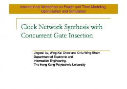
Relative energy normalized to the baseline.
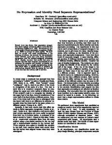
B. Results Figure 4 shows the overall energy saving for both the static and the dynamic victim cache policies broken down by different energy components. The energy measured includes both the local and victim caches (shown by LLC STAT and LLC DYN) and the main memory power (shown by DDR STAT and DDR DYN). We run 1 to 4 threads in the four CPUs of the first socket. Results on the left are for one core active, but we show the average results for more cores active. The static policy is able to save up to 33.5% of the energy over the baseline system with no victim cache for a single thread (astar). The energy savings comes from a combination of reduced DRAM accesses and increased DRAM idleness. We find that the dynamic energy of the cache is small compared to the dynamic energy of the
Relative DRAM requests normalized to the baseline.
120
baseline
100
static dynamic
80
60
40
20
mix3
mix4
mix2
mix1
avg 4 thread
avg 3 thread
avg 2 thread
avg 1 thread
libquantum
perl
sjeng
mcf
Fig. 6.
omnetpp
href
hmmer
gcc
gobmk
0
astar
terestingly, a threshold hit value of zero and a threshold dirty value of 100 gave the best results. The threshold hit of zero means that we would only shut down the victim cache if there were no victim hits in an interval, but that was actually a fairly frequent occurrence. The low value for threshold dirty was due in part to our small sample interval size (10000 memory transactions). We calculate the total power of the caches plus the memory system as the metric, since although DRAM energy is saved from lesser memory activity, extra power is consumed due to increased victim cache activity. Overall power is improved if more energy is saved in the DRAM than lost in the victim cache. For our workload we use the SPECCPU 2006 benchmark suite. A memory trace for each benchmark was obtained by fast-forwarding execution to the SIMPOINT [14] and then generating the trace for the next 200 million executing instructions. Our simulator models a 4-core processor per socket. A multi-program workload was generated by running multiple traces (4 in this case) of benchmarks in multiple cores. We examine both homogeneous and heterogeneous workloads. We used only the integer benchmarks for our evaluation since this set of applications have diverse memory characteristics with respect to number of read/writes per instruction, cache behavior, and memory footprints.
Fig. 5.
Miss Rate
Fig. 4.
pe rl sje ng lib q av th g re 1 aa th vdg re 2 aa th vdg re 3 aa th vdg re 4 ad m ix1 m ix2 m ix3 m ix4
gc c bm hm k m er hr ef om mcf n p etp go
ar bz ip
0
avg 1 thread avg 2 thread avg 3 thread avg 4 thread mix1 mix2 mix3 mix4
0
0.2
as t
static
bzip
Relative Energy Distribution
1.2
Overall miss rate.
DRAM since the latter populates the large row buffer (the size of a page). This results in high energy savings when we convert main memory accesses into victim cache hits. Figure 5 shows the number of DRAM requests, normalized to the baseline, while Figure 6 shows the impact on overall miss rate (counting victim cache hits). We find that the number of DRAM requests has reduced dramatically for many benchmarks, 15% on average. Not surprisingly, we see from these two figures that energy savings is highly correlated with the reduction in DRAM accesses. astar, gcc, mcf and omnetpp all make excellent use of the extra socket as a victim cache. However, several benchmarks get no significant gain from the larger effective cache size afforded by the extra socket. In those cases, we see that the ineffective use of the victim cache results in wasted energy, primarily in the form of static power dissipation of the remote socket LLC. These benchmarks either have very low miss ratio like hmmer, where addition of extra cache is unnecessary, or have extremely large memory footprints and little locality like sjeng and libquantum. For more than 2 threads, even non memory-intensive applications like bzip and href show significant improvement due to the increased pressure on the shared last level cache, as indicated by a 9% overall energy saving for 4 threads with the dynamic policy.
Distribution of DRAM states
baseline static dynamic
1.2
ACT_STBY
PRE_STBY
PRE_PDN
1
0.8
0.6
0.4
0.2
Fig. 7.
lib q av th g re 1 aa th vdg re 2 aa th vdg re 3 aa th vdg re 4 ad m ix1 m ix2 m ix3 m ix4
rl ng
pe
sje
as
ta r
bz ip gc go c bm hm k m er hr ef om mcf n p etp
0
DRAM state distribution.
bzip shows 9.2% and 18.8% energy savings while href shows 5.2% and 32.9% savings for 3 and 4 threads, respectively (not shown individually in the graph). We also investigate four heterogeneous workloads mix1 (astar, gcc, mcf, omnetpp), mix2 (astar, gcc, gobmk, hmmer), mix3 (mcf, omnetpp, perl, sjeng) and mix4 (hmmer, href, perl, sjeng) created by mixing benefiting and non-benefiting benchmarks. For mix1 we find that all the benefiting benchmarks are competing for the victim cache, resulting in a low overall energy improvement. For mix2 and mix3 only half of the benchmarks are utilizing the victim cache — lower competition results in more effective use of the victim cache. For mix4 all the benchmarks were non-benefiting and together still show energy degradation with the victim cache policy. For those workloads where the victim cache was of little use, our dynamic victim cache policy was much more effective at limiting wasted energy on unprofitable victim cache usage. As a result, the negative results are minimal when the victim cache is not effective (below 0.5% in most cases), and we still achieve most of the benefit when it is – resulting in an overall decrease in energy to the memory subsystem. What negative effects remain are chiefly due to the occasional re-sampling to confirm that the victim cache should remain off. Identifying more sophisticated victim effectiveness prediction is a topic for future work. We save power every time we avoid an access to the DRAM. But this is often more than just the power incurred for the access. In many cases, avoiding an access also prevents a powered-down DRAM from becoming active, or avoids resetting the timer on an active device, which prevents it from powering down at a later point. Figure 7 shows the distribution of power states in all DRAM devices. In those applications where the DRAM access rate decreased, we find that the percentage of time spent in the power-down mode is increased, in many cases dramatically. Even with four threads, when the power-down mode is least used, the victim cache is still able to increase its use. V. C ONCLUSION This paper describes inter-socket victim-cacheing, which uses idle processors in a multi-socket machine to enable
significant increase in energy efficiency. This research uses the shared last-level cache of idle cores as a victim cache, holding data evicted from the LLC of the active processor. In this way, power-hungry DRAM reads and writes are replaced by cache hits on the idle socket. This requires minor changes to the memory controller. We demonstrate both static and dynamic victim cache management policies. The dynamic policy is able to disable victim cache operation for those applications that do not benefit, without significant loss of the efficiency gains in the majority of cases where the victim cache is effective. Intersocket victim cacheing typically improves both performance and energy consumption. Overall energy consumption of the caches and memory is reduced by as much as 32.5%, and averages 5.8%. VI. ACKNOWLEDGMENTS The authors would like to thank the reviewers for their helpful suggestions. This work was funded by support from Intel and NSF grant CCF-0702349. R EFERENCES [1] L. A. Barroso and U. H¨olzle, “The case for energy-proportional computing,” IEEE Computer, January 2007. [2] P. Padala, X. Zhu, Z. Wang, S. Singhal, and K. G. Shin, “Performance evaluation of virtualization technologies for server consolidation,” HP Laboratories, Tech. Rep., April 2007. [3] A. R. Lebeck, X. Fan, H. Zeng, and C. Ellis, “Power aware page allocation,” in Proceedings of the 9th international conference on Architectural support for programming languages and operating systems, November 2000. [4] V. Delaluz, A. Sivasubramaniam, M. Kandemir, N. Vijaykrishnan, and M. J. Irwin, “Schedular based dram energy management,” in 39th Design Automation Conference, June 2002. [5] H. Huang, P. Pillai, and K. G. Shin, “Design and implementation of power aware virtual memory,” in USENIX Annual Technical Conference, June 2003. [6] N. P. Jouppi, “Improving direct-mapped cache performance by the addition of a small fully-associative cache prefetch buffers,” in 17th International Symposium on Computer Architecture, May 1990. [7] J. Chang and G. S. Sohi, “Cooperative cacheing for chip multiprocessors,” in Proceedings of the 33rd annual international symposium on Computer Architecture, June 2006. [8] M. Feeley, W. E. Morgan, F. H. Pighin, A. R. Karlin, H. M. Levy, and C. A. Thekkath, “Implementing global memory management in a workstation cluster,” in Proceedings of the fifteenth ACM symposium on Operating systems principles, December 1995. [9] C. H. Kim, J. W. Kwak, S. T. Jhang, and C. S. Jhon, “Adaptive block management for victim cache by exploiting l1 cache history information,” in International conference on embedded and ubiquitous computing, August 2004. [10] G. Memik, G. Reinman, and W. H. Mangione-Smith, “Reducing energy and delay using efficient victim caches,” in Proceedings of international symposium on Low power electronics and design, August 2003. [11] X. Fan, C. S. Ellis, and A. R. Lebeck, “Memory controller policies for dram power management,” in Proceedings of the International Symposium on Low Power Electronics and Design, August 2001. [12] D. M. Tullsen, S. J. Eggers, and H. M. Levy, “Simultaneous multithreading: maximizing on-chip parallelism,” in 22nd International Symposium on Computer Architecture, June 1995. [13] S. Thoziyoor, N. Muralimanohar, J. H. Ahn, and N. P. Jouppi, “Cacti 5.1,” HP Laboratories, Tech. Rep., 2008. [14] T. Sherwood, E. Perelman, and G. Hamerly, “Automatically characterizing large scale program behavior,” in Proceedings of the 10th international conference on Architectural support for programming languages and operating systems, October 2002.