Knee Surg Sports Traumatol Arthrosc DOI 10.1007/s00167-017-4640-5
KNEE
Internal femoral component rotation adversely influences load transfer in total knee arthroplasty: a cadaveric navigated study using the Verasense device William A. Manning1 · Kanishka M. Ghosh1 · Alasdair Blain2 · Lee Longstaff1,3 · Steven P. Rushton2 · David J. Deehan1,4
Received: 6 January 2017 / Accepted: 7 July 2017 © The Author(s) 2017. This article is an open access publication
Abstract Purpose and hypothesis Correct femoral component rotation at knee arthroplasty influences patellar tracking and may determine function at extremes of movement. Additionally, such malrotation may deleteriously influence flexion/extension gap geometry and soft tissue balancing kinematics. Little is known about the effect of subtle rotational change upon load transfer across the tibiofemoral articulation. Our null hypothesis was that femoral component rotation would not influence load across this joint in predictable manner. Methods A cadaveric study was performed to examine load transfer using the orthosensor device, respecting laxity patterns in 6° of motion, to examine load across the medial and lateral compartments across a full arc of motion. Mixed-effect modelling allowed for quantification of the effect upon load with internal and external femoral component rotation in relation to a datum in a modern singleradius cruciate-retaining primary knee design. Results No significant change in maximal laxity was found between different femoral rotational states. Internal * David J. Deehan
[email protected] http://www.nstcsurg.org 1
Newcastle Surgical Training Centre Research Centre, Freeman Hospital, High Heaton, Newcastle upon Tyne NE7 7DN, UK
2
School of Biology, University of Newcastle Upon Tyne, Newcastle upon Tyne NE1 7RU, UK
3
Department of Orthopaedics, University Hospital of North Durham, Durham DH1 5TW, UK
4
Institute of Cellular Medicine 4th Floor William Leech Building, Medical School, Newcastle upon Tyne NE2 4HH, UK
rotation of the femoral component resulted in significant increase in medial compartment load transfer for knee flexion including and beyond 60°. External rotation of the femoral component within the limits studied did not influence tibiofemoral load transfer. Conclusions Internal rotation of the femoral component will adversely influence medial compartment load transfer and could lead to premature polyethylene wear on the medial side. Keywords Femoral rotation · Load · Flexion · Knee arthroplasty
Introduction Total knee arthroplasty (TKA) is designed to alleviate pain and restore function with optimal active range of movement. Contemporary primary knee replacement is met with 10-year survivorship in excess of 95%, up to 20% of the patient cohort remain less than entirely satisfied and early revision for loss of movement and pain is a significant clinical worry [1, 21, 35, 41]. In both registry and singleinstitution series, up to 20% of the patient group remain dissatisfied with the final outcome with greater than 50% of such cases related to poor movement or lack of stability and unexplained pain [4]. Modern designs of cruciateretaining knee replacement systems aim to distribute load evenly across the articulating surfaces so as to both reduce polyethylene wear rates and ultimately the TKA revision burden [24]. The kinematic performance of the artificial knee is reliant upon exact placement with respect to the soft tissue envelope of the tibiofemoral and patellofemoral articulations [29]. The common denominator for both is the femoral component.
13
Vol.:(0123456789)
Femoral component placement may be performed using either a gap balancing or measured technique [26, 34]. No technique is consistently superior or reliable for femoral component placement [38]. Gap balancing is reliant upon correct tibial resection; otherwise, there is a compound error [14, 22]. Measured resection may introduce a malrotation due to difficulty identifying key anatomical landmarks [25, 43]. Femoral component malrotation will deleteriously influence the geometry of the flexion gap and patellar tracking [2, 17]. Load and constraint enjoy a complex and not always inverse relationship, and the flexion gap works with the soft tissue envelope and final laxity pattern to determine load across the flexed knee [8, 14]. Abnormal load may cause pain and stiffness. Our current standard biomechanical assessment is restricted to standing alignment views, and our knowledge of tibiofemoral load transfer in flexion is limited. A greater understanding of the load distribution across the tibiofemoral articulation under defined laxity conditions would allow for the study of the kinematic effect of component rotation and therefore subsequently predict the clinical performance of such a prosthetic joint [20]. In this study, we performed work to quantify the effect of femoral component rotation upon knee laxity and tibiofemoral contact force. Our primary (null) hypothesis was that femoral component rotation would neither influence load transfer across the tibiofemoral articulation nor maximal laxity for the knee arthroplasty construct at key points of knee flexion.
Knee Surg Sports Traumatol Arthrosc
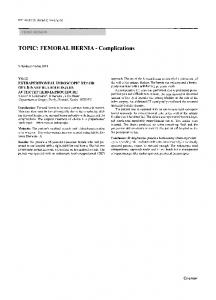
medial hamstring apparatus were individually loaded in a physiological manner direction (Fig. 1). Navigation trackers (Stryker eNdtrac Knee Navigation System, Michigan USA) were fixed to the femur and tibia 25 cm from the joint line, respectively, and in such a manner as to avoid interfering with muscle pull [5]. Previous work had validated the use of eight limbs and confirmed that this provides sufficient power to identify significant differences using this technique with 95% confidence presuming 80% power [8, 22]. Surgical procedure Insertion of a Stryker Triathlon (Michigan USA) singleradius cruciate-retaining TKA (CR-TKA) via a medial parapatellar approach was undertaken using a measured resection technique [27, 34]. The femoral component rotation was determined using the transepicondylar axis, validated using the mid-trochlear axis. A balanced knee was confirmed as that where after minimal soft tissue release, there was passive full extension, full flexion with normal ‘no touch’ patellar tracking, less than grade 1 laxity for varus valgus stressing at 0°, 30°, 60° and 90° of flexion, firm endpoint to Lachman testing and no laxity for anteroposterior stressing at 90° of flexion. To achieve such, 8 mm of distal femoral resection was performed at 5° valgus intramedullary alignment. Femoral sizing was undertaken using anterior referencing. The mid-point of
Materials and methods Specimen demographics This work was performed under formal ethical approval and UK HTA licence within the surgical training facility xxxxxxxxxxx (Human Tissue Act 2004, section 16/2, licence number 12148). Whole lower limb cadaveric material without pre-existing radiographic evidence of malrotation/fracture/deformity or arthritic disease was used. Eight fresh frozen lower limbs disarticulated at the hip (three right, five left from Caucasian donors with median BMI 22, range 17–28, male/female ratio 7:1, and mean age 74, range 64–79 years) were prepared in a standardised manner as reported in previous published work [6, 9, 14]. Limbs were mounted onto a custom rig with the tibia hung vertically and secured using set screws to prevent specimen rotation. All muscle groups acting across the knee joint were loaded throughout the experimental procedure using previously validated methodology for the study of cadaveric knee kinetics. In particular, the iliotibial band (ITB), quadriceps muscle group, biceps tendon and
13
Fig. 1 Experimental setup with custom jig and cadaveric limb loaded using a cable and pulley system to load in physiological directions. ITB 30 N, vastus lateralis 71 N rectus femoris and vastus intermedialis 61 N, vastus medialis 42 long and short head biceps femoris 44 N, semimembranous and semitendinosus 44 N. An arthrotomy has been performed (inset picture right) showing the Verasense tibial device is in situ with wireless hub connected to display unit (inset picture left). Navigation sensors on tibia and femur track motion and enabling laxity measurements
Knee Surg Sports Traumatol Arthrosc
the medial epicondyle may be difficult to localise but to reduce any peroperative error both senior authors agreed the mid-point of such so as to define the epicondylar axis. The rotation of the final 4 in 1 femoral cutting block was further validated using the mid-sulcus or Whiteside line. The tibia was then prepared using a 9-mm resection from the superiormost tibial condyle in a plane perpendicular to the anatomical axis with an associated 3° posterior slope achieved via an extra-medullary jig. The tibial cutting block was centred at the mid-third of the tibial tubercle and formal resection performed. The trial tibial baseplate was centred without restraint on the cut surface. Final orientation of the tibial component was determined after cycling the knee >20 times. The final seated position which achieved greatest conformity was marked on the anterior tibial crest using diathermy. For each experiment and each position of femoral component rotation, the tibial component was allowed to find its most conforming position. A standard polyethylene insert was selected and inserted with trial components to ensure the flexion and extension gaps were stable for varus valgus and anteroposterior stressing at the defines points of flexion stated earlier. Full extension was confirmed. The flexion gap allowed for full flexion but was balanced such as to ensure no opening in deep flexion. So as to optimise femoral component stability on the distal femoral resection, lughole screws were inserted and captured the femoral component whilst being buried and not interfering in articulation with the poly-component. This ensured absence of component rotation or glide or translation at any point of the experimental stressing in 6° of motion during the flexion/extension arc of the experiment (Fig. 2). A Verasense (Orthosensor, Dania FL) of appropriate thickness then replaced the polyethylene insert. With the knee held in 10° of flexion, the tibial rotation was adjusted and secured when the Verasense system registered a parallel contact point rotation [12]. Medial and lateral tibiofemoral contact forces were recorded as the loaded knee was taken through a range of passive flexion without stressing. No procedure required more than a simple periarticular medial or lateral capsular release to satisfy our criteria for balancing as defined by confirming the load across the medial and lateral compartments were within 15lbs (pounds-force) of each other, respectively, through a full arc of motion (Fig. 2) [12, 45]. This state defined the datum for femoral component rotation for each knee. To allow for ±3° of femoral rotation whilst maintaining the original component size, femoral cuts were downsized by 2 mm. The externally rotated (ERF-TKA) and internally rotated (IRF-TKA) states were achieved with the insertion of custom wedges (Fig. 3). The femoral component was fast secured following each rotation using custom cancellous thread lughole screws engaging the stronger subchondral bone. Care was taken to perform surgical closure of the
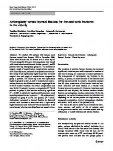
Fig. 2 Verasense display as viewed by the surgeon during balancing. This image shows a rotationally matched tibiofemoral construct as well as a balance soft tissue envelope as defined by medial and lateral compartments contact forces the within 15lbs
arthrotomy via interrupted mattress sutures respecting the anatomy of the parapatellar tissues prior to any testing [31]. The senior authors (xxx/xx) performed all surgical procedures and stress testing. For all experiments, there were two senior surgeons, a surgical assistant, a manual operator of the orthosensor system, a senior scientist recording the output from the navigation system. Data capture and analysis Data were captured, as per previous validated work, using a standard computerised navigation system with orthosensor provided range of compatible tibial trials [14, 37]. Knees were manually stressed to mimic intraoperative laxity assessment. A datum was taken from the knee in extension from which maximal displacements of the tibia in relation to the fixed femur were tracked via computer navigation (Stryker eNdtrac Knee Navigation System, Michigan, USA) to an accuracy of ±0.5 mm in 6° of freedom [5, 10, 28]. For each TKA condition, maximal displacements (anteroposterior, varus, valgus, internal and external rotation) were each recorded at five angles of flexion (0°, 30°, 60°, 90° and 110°). To reduce hysteresis, repeated flexion cycles were undertaken between measurements and ensured compartment forces remained constant during passive flexion. After each set of measurements, the output instrumentation was reset at zero. The Verasense device recorded tibiofemoral contact force (lbs/force) and contact points continuously during testing (millimetre accuracy ±2 mm—C. Anderson, OrthoSensor, personal communication 03.08.2015) with additional data capture under maximal stress at each of the five angles of flexion. Three knee conditions were defined
13
Knee Surg Sports Traumatol Arthrosc
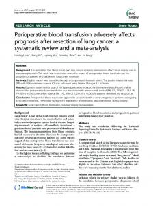
Fig. 3 Pictorial representation of femoral component alignment, exaggerated for demonstration, showing the neutrally aligned CRTKA (b), and the rotated femoral component to create the IRF-TKA (a) and ERF-TKA (c). Black lines demonstrating original femoral siz-
ing and red lines demonstrating the downsized femoral cuts (2 mm) to accommodate for component rotation. Custom polyethylene inserts d, f provide reproducible rotation whilst maintaining correct femoral size and implant stability aided by lughole screws e for stress testing
with the internal and external rotatory states compared with the neutral or datum. These were the internally rotated femoral component (IRF-TKA) and the externally rotated femoral component (ERF-TKA) (Fig. 3).
CR‑TKA laxity pattern
Statistical analysis Mixed-effect modelling was used to quantify the effect of flexion angle, direction of movement and implantation of TKA upon laxity [30, 32]. Displacements were used as the response variable, with TKA and flexion as covariates. Student’s t test was used to compare differences in tibiofemoral force and contact point measurements. Significance was set at a level of p