Int J Advanced Design and Manufacturing Technology, Vol. 7/ No. 4/ December - 2014
19
Investigating Temperature Effects on Mechanical Behavior of Rubber Compounds Embedded in Composite Structure of Pneumatic Tires H. Golbakhshi Department of Mechanical Engineering, Faculty of Engineering, University of Jiroft, Iran E-mail:
[email protected]
M. Namjoo* Mechanics of Biosystem Engineering Department, University of Jiroft, Iran E-mail:
[email protected] *Corresponding author Received: 17 May 2014, Revised: 13 August 2014, Accepted: 12 October 2014
Abstract: Owing to elastic and viscous characteristics of embedded rubber compounds, some of the supplied mechanical energy to composite structure of a rolling tire is dissipated as heat. As a result, the tire may have different body temperatures for different operating conditions. In most performed studies, just temperature distribution is investigated and the mechanical behaviour of tire structure, which is highly temperature-dependent, is ignored. In this study a 3D finite element model is developed for evaluating the effects of loading conditions and the body temperature on mechanical behaviour of the tire. The obtained results are compared with related published works to evaluate the accuracy of the analysis.
Keywords: Body Temperature, FEM Analysis, Pneumatic Tire, StressDeformation Field Reference: Golbakhshi, H., Namjoo, M., “Investigating the Effect of Temperature on Mechanical Behavior of Rubber Compounds Embedded in Composite Structure of Pneumatic Tires”, Int J of Advanced Design and Manufacturing Technology, Vol. 7/ No. 4, 2014, pp. 19-25. Biographical notes: M. Namjoo received his MSc in Mechanics of Agricultural Machinery from Isfahan University of Technology, Isfahan, in 2010. He is currently lecturer at Department of Agricultural Engineering & Mechanics, University of Jiroft. His research interests are in the areas of FE methods, design and developing agricultural machineries and structural optimization. H. Golbakhshi received his MSc degree from the Shahid Bahonar University of Kerman, Kerman, in 2010, in mechanical engineering. He is currently lecturer at the Department of Mechanical Engineering, University of Jiroft. His research interests include modelling and simulation of dynamic systems, and heat transfer simulation with FEM software.
© 2014 IAU, Majlesi Branch
20 1
Int J Advanced Design and Manufacturing Technology, Vol. 7/ No. 4/ December– 2014 INTRODUCTION
The rubber ability to withstand high static and dynamic loads and enduring large amounts of deformations, raises widespread applications in several industries such as automotive and aerospace. The visco-elastic properties of rubber have a great effect on reducing the vibration and noise of mechanical systems [1]. One of the most important applications of the rubber is in composite structure of pneumatic tires. So, the tire exhibits both elastic and viscous characteristics due to embedded rubber parts. As a result of periodic deformations, which impose time dependent loads on the tire, hysteretic loss occurs and some of restoring strain energy is dissipated into heat. Because of low thermal diffusivity, the temperature locally rises inside the tire structure and as a direct consequent, the rubber fatigue strength and its adherence with the road will be badly affected. So, the thermal aspects should be considered for long service life and optimal operation of vehicles tire [2-4]. On the other hand, it is also noticed that the mechanical properties of rubber have considerable variations with temperature [5]. Therefore, it is necessary to investigate the stress and deformation gradients of rolling tires under a variety of season conditions [6]. Using finite element method (FEM), various researches have been carried out for thermal analysis of rolling tires. Assuming that the inelastic energy of a rolling tire is completely converted into heat, Mc Allen et al. conducted a numerical model for thermal analysis [7]. A simplified 3D FE analysis is presented by Lin and Hwang for estimating the tire temperature rise under different working conditions [8]. Bazlamit et al. evaluated the effect of tire temperature on slippage of high speed vehicles over the road surface [9]. Later, for improving the thermal analysis of tires, the stresses and strains of nodes obtained from the mechanical analysis, were fitted by Fourier series to calculate the volumetric heat generation inside the tire structure [10]. In most of the works temperature distribution is considered as the major objective of the performed analyses. However, the mechanical properties of the rubber have great variations with temperature [2], [4], [7], [8], [10]. So, it is necessary to investigate the stress and deformation created in a rolling tire under a variety of tire body temperatures. In the present study, a nonlinear finite element analysis with great care on geometrical and mechanical details is presented for evaluating the nodal stresses and displacements and stored strain energy within material elements of the tire under variety of working temperatures. The available experimental and numerical data are used for verification of the obtained results.
© 2014 IAU, Majlesi Branch
2 MATERIALS AND METHOD
2.1. Rubber material model Since rubber is a highly extensible material, smallstrain elasticity theory is not suitable for describing the responses of tires to large deformations. Therefore, the incompressible hyper-elastic Mooney-Rivlin model is commonly used for simulating the real-world material behaviour of the tire [11-14]. According to this model, the stresses are obtained from the partial derivatives of the strain energy functions as [15]:
U
2 1
3
U I1 U I 2 . . I1 I 2
U U I I 1 2
(1)
is the stress, U is the strain energy function, is the stretch ratio and I1 , I 2 are the two first
Where
deviator of strain invariants. Therefore, the strain energy used in the model is: U C01 I1 3 C10 I 2 3
(2)
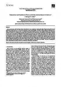
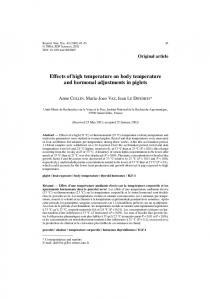
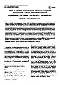
In Eq. (1) coefficients C01 and C10 are the MooneyRivlin constants which can be experimentally determined for different working temperatures [16-18]. Applying loads and boundary conditions to the nonlinear FE analysis, the distribution of stress and deformation can be estimated for the tire. 2.2. Simulation details The size of a standard passenger tire (185/60 R15) is used for modelling and simulation in this work. For simplicity, the tire is assumed to be composed of carcass-ply, Steel belt layers, tread, and bead. As shown in Fig. 1, for establishing a 3D finite element model, the tire cross section is first developed according to actual size of the tire, and then rotated by 360o along the circumferential direction. So, only circumferential grooves are considered for tread blocks. The tread as an isotropic and homogenous rubber is built by solid element with Mooney-Rivlin hyper-elastic property. The carcass-ply and bead are also created as solid element with elastic properties shown in table 1 [6]. The meshed model contains a total number of 60661 nodes and 33565 elements with an aspect ratio varying from 1 to 3.5 and dense mesh in the vicinity of tire footprint (Fig. 2). For each body temperature and loading condition, an axisymmetric distribution of temperature can be found inside the tire
Int J Advanced Design and Manufacturing Technology, Vol. 7/ No. 4/ December - 2014 [19], [20]. However, an average value is considered for body temperature in this work. 1- Tread 2- Steel belt layers 1
3- Carcass 2
4- Sidewall 5- Bead 3
(a)
21
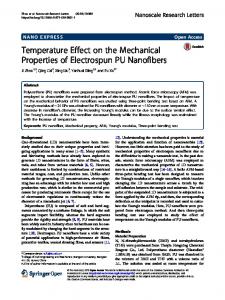
Assuming the material properties of other components do not change with the temperature, the MooneyRivilin constants are selected for three different temperatures 10 C , 15 C and 40 C as shown in table 1 [4]. To guarantee the computation accuracy and reduce processing time, the boundary conditions are applied to the half of created model for the tire (Fig. 3). For the treads adjacent to the road, the node to surface contact condition are applied. The inflation pressure is uniformly distributed over internal surfaces of the tire and the tire-rim contact region is considered to be clamped. The axle load is then applied to the inflated tire.
4
5
(b)
(c)
Fig. 2 The axisymmetric modelling of tire (185/60 R15) geometry and meshing used in this study Fig. 1 (a) Structure of a common radial-ply tire, (b) Cross section of model of tire constructed according to the actual size of radial tire in Solidworks Simulation and (c) Cross section of radial tire 185/60R15.
Load
Table 1 Material properties used in tire FE model Tread Bead Carcass Temperature, -10 15 40
C MooneyRivlin constants Mpa
Load
C01
8.061
2.0477
0.550966
-
C10
1.806
1.1859
0.00373778
-
1400
1140
1100
Density,
m
4800
Pressure
(b)
1390
(a)
kg
3
Modulus of elasticity, E Gpa
-
Poisson ratio,
-
200
0.794 Fig. 3 Imposition of boundary conditions: a) tire/road contact and b) inserting inflation pressure on tire inner surface
0.3
0.45
© 2014 IAU, Majlesi Branch
22 3
Int J Advanced Design and Manufacturing Technology, Vol. 7/ No. 4/ December– 2014 RESULTS AND DISCUSSIONS
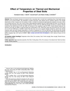
For a variety of inflation pressure, vertical displacements of tire hub center, loaded by axle force F 4 kN is evaluated using a 3D finite element model. Data of the experimental investigation are used to verify the obtained results. The rubber temperature is
observations closely match the published results reported by researchers [6], [23], [24]. For different tire temperatures, the variations in maximum values of vonMises stress during 1 second are illustrated in Fig. 6. It is found that any change in temperature has a considerable effect on created stresses inside the tire.
considered to be 25 C during the tests. As depicted in Fig. 4, it is clear that the simulation results have a good consistency with the empirical observations. Moreover, the obtained results have a good agreement with the outputs of results presented by Behroozi et al., for analysis of aircraft tire [21], [22].
Fig. 6 Maximum von-Mises stress at 1 second simulation time.
Fig. 4 Tire hub displacements versus inflation pressure
Fig. 5 Maximum hub displacements with simulation time of 1 second for three different temperature values.
For three different temperatures of the rubber, Fig. 5 depicts the variations of hub displacement during 1s of the simulation. The tire is inflated by 35 psi and loaded with 4kN . It is clear that for the same inflation pressure and axle load, the calculated values of displacement increases from 10 C to 40 C . These © 2014 IAU, Majlesi Branch
The contours of von-Mises stress are depicted in Fig. 7. According to the results, the stress decreases from the contact region to top and the maximum von-Mises stress occurs in the sidewall. This result agrees with the simulation result of Yanjin et al. and Smith et al. [19, 23]. It is also noted that as the temperature rises, increased amount of stresses are created inside the tire. The maximum von-Mises stress values of 2.97e7 , 3.97e 7 and 4.66e7 Pa are obtained for the tire with the body temperatures 10 C , 15 C and 40 C , respectively. Under different rubber temperatures, the contours of nodal displacement are presented in Fig. 8. It can be seen that the high nodal displacement fields are accumulated in two sides close to the bottom of the tire and the area of the high nodal displacement increases with the increase of the tire temperature. Variations of tire total strain energy with the tire body temperature are shown in Fig. 9. It is obvious that less amount of strain energy is stored in a tire with lower temperature. These conclusions are fully consistent with the results of Smith et al., [19]. In many published works, the lost strain energy is assumed to completely contribute to internal heat generation and rolling resistance [3], [14], [25]. So, the loaded tire should have a limited amount of stored strain energy during the operation. For the same axle load and inflation pressure, variations of contact pressure at tire/road interaction surface are depicted in Fig. 10. The greater amount of contact pressure can be found for the tire with higher body temperature.
Int J Advanced Design and Manufacturing Technology, Vol. 7/ No. 4/ December - 2014
(a)
(b)
23
(c)
Fig. 7 Stress contours of tire at time step 10 for three temperatures: (a) 10 C ; (b) 15 C and (c) 40 C
(a)
Fig. 8
(a)
Fig. 9
(b)
(c)
Nodal displacement counters of tire for three temperatures: (a) 10 C ; (b) 15 C and (c) 40 C
(b)
(c)
Contour plots of elastic strain energy density of a steady-state rolling tire generated by P 35 psi , F 5 kN for three temperatures: (a) 10 C ; (b) 15 C and (c) 40 C
.
© 2014 IAU, Majlesi Branch
24
Int J Advanced Design and Manufacturing Technology, Vol. 7/ No. 4/ December– 2014
(a)
Fig. 10
(b)
(c)
Contours of contact stress at tire/road interaction surface obtained at three temperatures: (a) 10 C ; (b) 15 C and (c) 40 C
The output results for contact area are plotted versus tire temperature in Fig. 11. As the temperature increases the tire/road contact area will expand, the fact that have a considerable effect on fuel consumption of the vehicle [26]. For comparison, the results of experimental analysis for contact area are also plotted in the Fig. 11, where the results given by the numerical analysis have a good agreement.
4
CONCLUSION
In the present study the stress, nodal displacement and stored strain energy of radial tire 185/60R15 are well predicted for different body temperatures. The results indicate that the maximum von-Mises stress concentrates on the sidewalls and increases with the increase of tire body temperature. High nodal displacement fields are accumulated in two sides close to the bottom of the tire. It is found that the increase in tire temperature leads to large nodal displacements. The results show that for 25 C difference in tire temperature, the maximum values for hub displacement and created stress is increased by 115% and 40%, respectively. Therefore, it seems that the tire deformation is more sensitive to temperature rather than stress. Furthermore, interaction of hotter tire with the road causes higher stresses at the contact surface which has undesirable effects on vehicle control and fuel consumption.
© 2014 IAU, Majlesi Branch
Fig. 11 Variation of tire/ road interaction surface with the temperature
REFERENCES [1] Zouaghi, A., Chafra, M., and Chevalier, Y., “Modeling of composite multilayer rubber-steel: vibro-acoustic insulation of vehicle brake system”, Mechanics & Industry, Vol. 13, No. 3, 2012, pp. 18595. [2] Sokolov, S., “Analysis of the heat state of pneumatic tires by the finite element method”, Journal of Machinery Manufacture and Reliability, Vol. 38, No. 3, 2009, pp. 310-4. [3] Cho, J. R., Lee, H. W., Jeong, W. B., Jeong, K. M., and Kim, K. W., “Numerical estimation of rolling resistance and temperature distribution of 3-D periodic patterned tire”, International Journal of Solids and Structures, Vol. 50, No. 1, 2013, pp. 8696.
Int J Advanced Design and Manufacturing Technology, Vol. 7/ No. 4/ December - 2014 [4] Li, Y., Liu, W., and Frimpong, S., “Effect of ambient temperature on stress, deformation and temperature of dump truck tire, Engineering Failure Analysis”, Vol. 23, 2012, pp. 55-62. [5] Kramer, O., Hvidt, S., and Ferry, J., “Science and Technology of Rubber, ed Mark James”, E, Erman, b and Eirich Frederick, R, Academic Press, New York, 222, 1994. [6] Li, Y., Liu, W. Y., and Frimpong, S., “Effect of ambient temperature on stress, deformation and temperature of dump truck tire”, Engineering Failure Analysis, Vol. 23, 2012, pp. 55-62. [7] Mc Allen, J., Cuitino, A., and Sernas, V., “Numerical investigation of the deformation characteristics and heat generation in pneumatic aircraft tires: Part II”, Thermal Modeling, Finite Elements in Analysis and Design, Vol. 23, No. 2, 1996, pp. 265-90. [8] Lin, Y.-J., Hwang, S.-J., “Temperature prediction of rolling tires by computer simulation”, Mathematics and Computers in Simulation, Vol. 67, No. 3, 2004, pp. 235-49. [9] Bazlamit, S. M., Reza, F., “Changes in asphalt pavement friction components and adjustment of skid number for temperature”, Journal of Transportation Engineering, Vol. 131, No. 6, 2005, pp. 470-6. [10] Wang, Z., “Finite Element Analysis of Mechanical and Temperature Field for a Rolling Tire (PDF)”, 2010. [11] Bolarinwa, E., Olatunbosun, O., “Finite element simulation of the tyre burst test”, Proceedings of the Institution of Mechanical Engineers, Part D: Journal of Automobile Engineering, Vol. 218, No. 11, 2004, pp. 1251-8. [12] Ghoreishy, M. H. R., “A state of the art review of the finite element modelling of rolling tyres”, Iranian Polymer Journal, Vol. 17, No. 8, 2008, pp. 571-97. [13] Ghoreishy, M. H. R., “Finite element analysis of the steel-belted radial tyre with tread pattern under contact load”, Iranian Polymer Journal, Vol. 15, No. 8, 2006, pp. 667-74. [14] Korunović, N., Trajanović, M., and Stojković, M., “Finite element model for steady-state rolling tire analysis”, Journal of the Serbian Society for Computational Mechanics, Vol, 1, No. 1, 2007, pp. 63-79. [15] Lahellec, N., Mazerolle, F., and Michel, J.-C., “Second-order estimate of the macroscopic behavior of periodic hyperelastic composites: theory and experimental validation”, Journal of the Mechanics and Physics of Solids, Vol. 52, No. 1, 2004, pp. 2749.
25
[16] Kongo Kondé, A., Rosu, I., Lebon, F., Brardo, O., and Devésa, B., “On the modeling of aircraft tire”, Aerospace Science and Technology, Vol. 27, No. 1, 2013, 67-75. [17] Holscher, H., Tewes, M., Botkin, N., Lohndorf, M., Hoffmann, K., and Quandt, E., “Modeling of Pneumatic Tires by a Finite Element Model for the Development a Tire Friction Remote Sensor”, Center of Advanced European Studies and Research (CAESAR), Ludwig-Erhard-Allee, 2: 53175, 2004. [18] Zhao, Z., Wang, Q., Li, J., Li, Y., and Chu, L., “Steady state thermal analysis on temperature field of tire based on rolling state”, Jixie Gongcheng Xuebao(Chinese Journal of Mechanical Engineering)(China), Vol. 37, No. 5, 2001, pp. 30-4. [19] Smith, R. E., Tang, T., Johnson, D., Ledbury, E., Goddette, T., and Felicelli, S. D. “Simulation of Thermal Signature of Tires and Tracks”, DTIC Document, 2012. [20] Tang, T., Johnson, D., Smith, R. E., and Felicelli, S. D., “Numerical evaluation of the temperature field of steady-state rolling tires”, Applied Mathematical Modelling, 2013. [21] Behroozi, M., Olatunbosun, O., and Ding, W., “Finite element analysis of aircraft tyre–Effect of model complexity on tyre performance characteristics”, Materials & Design, Vol. 35, 2012, pp. 810-9. [22] Danielson, K., Noor, A., and Green, J., “Computational strategies for tire modeling and analysis”, Computers & Structures, Vol. 61, No. 4, 1996, pp. 673-93. [23] Yanjin, G., Guoqun, Z., and Gang, C., “Influence of belt cord angle on radial tire under different rolling states”, Journal of reinforced plastics and composites, Vol. 25, No. 10, 2006, 1059-77. [24] Ghoreishy, M. H. R., “A Numerical Study on the Non-linear Finite Element Analysis of a Tyre under Axisymmetric Loading”, Iranian Polymer Journal, Vol. 11, No. 5, 2002, pp. 325-32. [25] Ebbott, T., Hohman, R., Jeusette, J.-P., and Kerchman, V., “Tire temperature and rolling resistance prediction with finite element analysis”, Tire Science and Technology, Vol. 27, No. 1, 1999, pp. 2-21. [26] Meschke, G., Payer, H., and Mang, H., “3D Simulations of automobile tires: Material modeling, mesh generation, and solution strategies”, Tire Science and Technology, Vol. 25, No, 3, 1997, pp. 154-76.
© 2014 IAU, Majlesi Branch