Dec 12, 2014 - This paper was selected for presentation by an IPTC Programme Committee following review of information contained in an abstract submitted ...
IPTC-17776-MS A Novel Autonomous Inflow Control Device Design: Improvements to Hybrid ICD Quanshu ZENG, Zhiming WANG, Xiaoqiu WANG, Yiwei LI, and Weilin ZOU, China University of Petroleum-Beijing; Jingnan XIAO, Sinopec Petroleum Engineering Technology Research Institute; Tian CHEN, CNPC Bohai Drilling Engineering Company Ltd; Gang YANG, China United Coalbed Methane Corporation Ltd; Quan ZHANG, Research Institute of Oil & Gas Eng., PetroChina Tarim Oilfield Company
Copyright 2014, International Petroleum Technology Conference This paper was prepared for presentation at the International Petroleum Technology Conference held in Kuala Lumpur, Malaysia, 10 –12 December 2014. This paper was selected for presentation by an IPTC Programme Committee following review of information contained in an abstract submitted by the author(s). Contents of the paper, as presented, have not been reviewed by the International Petroleum Technology Conference and are subject to correction by the author(s). The material, as presented, does not necessarily reflect any position of the International Petroleum Technology Conference, its officers, or members. Papers presented at IPTC are subject to publication review by Sponsor Society Committees of IPTC. Electronic reproduction, distribution, or storage of any part of this paper for commercial purposes without the written consent of the International Petroleum Technology Conference is prohibited. Permission to reproduce in print is restricted to an abstract of not more than 300 words; illustrations may not be copied. The abstract must contain conspicuous acknowledgment of where and by whom the paper was presented. Write Librarian, IPTC, P.O. Box 833836, Richardson, TX 75083-3836, U.S.A., fax ⫹1-972-952-9435
Abstract In long horizontal wells, early water or gas may breakthrough into the wellbore due to the imbalanced production profile caused by the heel-toe effect, reservoir anisotropic, reservoir heterogeneity or fractureexisting. Once coning occurs, oil production may severely decrease due to the limited flow contribution from the non-coning regions. Inflow control devices (ICD) are installed to maintain the flow across production zones uniformly by creating an additional pressure differential which cancels out the imbalanced production profile. This will lower startup production, however, unwanted fluids from breaking through are significant delayed, and total oil production is maximized. Unfortunately, once water/gas does break through, they will take over the well, significantly reducing oil production. In this paper, a novel autonomous inflow control device (AICD) design is proposed on the combination of hybrid ICD and water swelling rubber (WSR). The WSR installed in the slot will swell once water breakthrough occurs, and the swell increment will be adjusted automatically according to the water content, thus changing the minimum flow area and the flow resistance rating (FRR). This autonomous function enables the well to produce oil while restrict water. To highlight the excellent performance of the novel design, four other designs (nozzle-based, helical channel, tube-type, and hybrid) with a same FRR were compared, with structural parameter optimization, and fluid property sensitivities researched. The results show that the novel design has good performances during every phase of a well’s life: high plugging resistance at startup, high erosion-resistant during peak production, continuous inflow control and low viscosity sensitivity during declining, and significantly flow resistance increase at eventual water onset.
Introduction In long horizontal wells, early water or gas may breakthrough into the wellbore due to the imbalanced production profile caused by the heel-toe effect[1–2], reservoir anisotropic[3], reservoir heterogeneity[4] or
2
IPTC-17776-MS
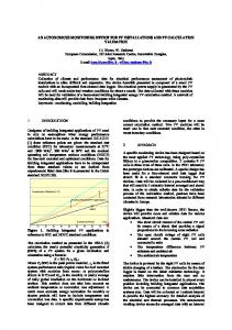
Figure 1—Structure Diagram of Novel Autonomous Inflow Control Device Design
fracture-existing[5]. Once coning occurs, water/gas fast track will be generated, and then oil production may severely decrease due to the limited flow contribution from the non-coning regions. To eliminate these issues, inflow control devices (ICD) are downhole tools which are placed in every screen joint to balance the production inflow profile across the entire lateral length and to compensate for permeability variations. Currently, various ICDs have been developed in the industry. These ICDs can be divided into passive inflow control devices (PICD) and autonomous inflow control devices (AICD) according to whether their flow resistance ratings (FRR) are constant. The PICDs are usually installed to maintain the flow across production zones uniformly by generating an additional pressure drop. They use restriction mechanism (the nozzle-based type[6], and the orifice type[7]), friction mechanism (the labyrinth type[8], and the helical channel type[9]) or cooperating both the mechanisms (the hybrid type[10–11],and the tube type[12]) to generate the similar pressure drop. Their FRRs are fixed, and unfortunately, once water/gas does breakthrough, the low viscosity water/gas will take over the well, thus rendering the PICD useless and significantly decreasing the oil production. AICD is a new concept, which will generate a much larger flow resistance once water/gas does breakthrough, thereby the water/gas production is limited and the oil production is guaranteed. This autonomous function enables the well to continue producing oil for a longer time. The Counterweight Flapper AICD[13] uses the difference between oil and gas densities to control the open or close of a flapper; however, the movable flapper is more likely to malfunction, and the device can’t control water coning effectively due to the small difference between oil and water densities. The RCP valve[14] uses the balance of dynamic pressure and static pressure to control the position of a movable disk; however, the disk may be ruined by the pressure difference exerted on it if the difference is larger than a certain value. And the Equiflow AICD[15] uses the balance between the inertial forces and the viscous forces in the fluid to change the passages; however, the device has a small oil viscosity range available for each specific design. Since a typical well with ICDs is usually in production from 5 to more than 20 years, the long-term reliability of such device is crucial to the well’s overall success. Thereby the ICD must have certain performance features during every phase of the well’s life to minimize or eliminate the undesirable results[16]. However, the reality is that none of current ICDs alone meet the ideal requirements of an ICD designed.
Novel AICD Design Aiming at solving these, a novel autonomous inflow control device (Fig. 1) is proposed on the combination of hybrid ICD and water swelling rubber (WSR). As can be observed, the novel design
IPTC-17776-MS
3
Figure 2—Diagram of Min. Flow Area for Different Water Content
incorporates a series of bulkheads, flow slots, and water swelling rubber. Similar to the standard hybrid ICD, each of the bulkheads has two flow slots cut at 180° angular spacing, and each set of slots staggered a 90° phase with the next set, thus the flow must turn after passing through each set of slots, and jetting effect is prevented. What’s more, the WSR installed in the slot will swell once water breakthrough occurs, and the swell increment will be adjusted automatically according to water content (Fig. 2). The water swelling rubber is of a Figure 3—FRR versus Water Content dynamic balance, swelling to change the minimum flow area. To be specific, for low water content, the swell increment of WSR is limit, and the corresponding minimum flow area is maximized; as the water content increases, the WSR begins to swell, and the minimum flow area gets smaller; for high water content, once WSR is fully expanded, its minimum flow area is minimized. As previously described, the primary pressure drop mechanism of the novel design is restrictive, but in a variable distributive configuration. Pressure is reduced sequentially as flow passes through each successive chamber that is formed by the bulkheads. The FRR mainly depends on the minimum flow area which is corresponding to water content. In other words, FRR is not a fixed value but increases along with water content, as shown in Fig. 3. Compared with oil (water content of 0%), water (water content of 100%) has nearly 40 times as FRR of the device. The design also makes adjustment to different FRR simple, since the cumulative pressure drop is proportional to the number of bulkheads used. In general, the novel design uses continuous fluid constriction to generate a distributive differential pressure across the device, and the minimum flow area is variable. The benefits of the novel design are not only its simplified design, but also the good performances during every phase of a well’s life to minimize or eliminate the undesirable results. The design provides a large cross-sectional flow area and generates significantly low fluid velocity before water coning occurs, which results in high plugging resistance during mud flow back operations, and high erosion-resistant from fluid-borne particles during peak production. During declining, the novel design provides continuous inflow control to maintain the
4
flow uniformly by creating an additional pressure drop. At eventual water onset, the flow area is significantly decreased due to WSR increasement and a much lager flow resistance is generated instead, this autonomous function enables the well to continue producing oil for a longer time. In addition, the design makes adjustment to different FRR simple, since the cumulative pressure drop the device is proportional to the number of bulkheads used.
IPTC-17776-MS
Figure 4 —Computational Grid
Modeling and Analysis It’s hard to solve the complex multiphase flow of novel design with multiple inlets analytically, and experiments will spend plenty of manpower and material, while numerical simulation has been widely used on complex flow studies with the development of both computer competency and computational fluid dynamics (CFD) technology. Therefore, rules of oil-water two-phase flow through the novel design are studied by numerical simulation in this part, which further promote the fluid property sensitivity and structure parameter optimization in Figure 5—Corresponding Relationship between Water Content and part 4. Minimum Flow Area The three-dimensional mechanical model of the novel design is developed, which then the hydraulic model is obtained by Boolean operation and subsequently mesh is generated. In order to describe the flow around slots and ports more accurately, the mesh is divided into different regions and encrypted in these locations, which is shown specifically in Fig. 4, the total number of computational units are about 940,000. This model has two inlets and one outlet in total, both annulus inlet and base pipe inlet are set as velocity-inlet, while the outlet is set as outflow and the rest as wall. The water content is set to be a function of time by C language, which then imported to CFD software with the help of user defined function (UDF) technology. Sliding mesh technique is used which make the water content corresponds with the minimum flow area (Fig. 5). For flow direction assurance, the base pipe inlet is setup with a flow rate of 5m3/day. Standard - model is selected due to its high accuracy on simulating the turbulent flow while laminar model is selected on simulating the laminar flow. Mixture model is selected due to its high accuracy on simulating the oil-water two-phase dispersed flow while VOF model is selected on simulating the stratified flow. Since ICDs are usually installed horizontally, gravity is considered in the model. The contours of static pressure with varying water content are shown in Fig. 6. As can be observed from Fig.6, the primary pressure drop mechanism of the novel design is restrictive, but in a variable distributive configuration. Pressure is reduced sequentially as the flow passes through each successive chamber that is formed by the bulkheads, thus the design makes adjustment to different FRR simple. The minimum flow area will decrease automatically as the water content increases, thus changing the minimum flow area and FRR of the novel design. As a result, the novel design provides minimal resistance for oil and maximum resistance for water.
IPTC-17776-MS
5
Figure 6 —Contour of Static Pressure with Varying Water Content Table 1—Fluid Property Sensitivity Research Projects
Project 1 Project 2 Project 3
Water Content (%)
Oil Density (kg/m3)
Oil Viscosity (cP)
0, 10, 20, 30, 40, 50, 60, 70, 80, 90, 100 0, 50 0, 50
850 800, 850, 900, 950, 1000 850
10 1 1, 2, 4, 10, 20, 30, 50, 100, 150, 200
Comparation with Other Designs To highlight the excellent performance of the novel design, four other designs (nozzle-based, helical channel, hybrid, and tube-type) with a same FRR of 0.8 were compared. Where: the numbers of FRR represent the equivalent pressure drop magnitude expected in pressure units of bar when flowing at the following conditions[17]: fluid density of 998.2 kg/m3, fluid viscosity of 1.003 cP, and flow rate of 30 m3/day. These designs use restrictive and/or frictional mechanism to generate the similar pressure drop. Therefore, pressure drops created by different fluids through these ICDs vary a lot. The restrictive mechanism depends on the minimum flow area, flow rate, and fluid density, while the frictional mechanism depends on the flow path length, flow rate, and fluid viscosity. Although not all ICDs have same mechanisms, the factors that affect pressure drop can sum up in fluid properties and ICD geometries. Fluid Property Sensitivity Since fluid property sensitivity is a key performance characteristic that needs to be considered, three projects were developed respectively to describe the water content sensitivity, oil density sensitivity, and oil viscosity sensitivity of all these designs (Table 1). In particular, water property sensitivity is not consider due to its constant property. Project 1 researched on water content sensitivity. Water content (%) as follows: 0, 10, 20, 30, 40, 50, 60, 70, 80, 90, and 100. The relationships between water content and pressure drops of different designs as shown in Fig. 7. The pressure drops of the four passive designs will first increase then decrease with the increase of water content, and the boundary point lies in the place where the phase inversion point is. Unfortunately, the pressure drop generated by water is lower than that of oil or mixture in most cases. That is, once water/gas does break through, current passive ICDs will be ineffective. With the help of the novel
6
IPTC-17776-MS
Figure 7—Sensitivity Analysis of Water Content
Figure 8 —Sensitivity Analysis of Oil Density
design, the pressure drop generated by water has nearly 40 times the pressure drop generated by oil. And the pressure drop generated by mixture increases with water content. That is, the novel design provides an autonomous function that limiting the water production and guaranting the oil production. Project 2 researched on oil density sensitivity. Since typical density of oil range from 800 to 1000 kg/m3, oil density (kg/m3) as follows: 800, 850, 900, 950, 1000. The relationships between oil density and pressure drop of different designs are Figure 9 —Sensitivity Analysis of Oil Viscosity shown in Fig. 8. The pressure drop of all these designs increases linearly with oil density. The oil density sensitivities of these designs are not that the same, with the nozzle-based ICD an increase amplitude of 78.0 Pa/(kg/m3), the tube-type ICD of 47.6 Pa/(kg/m3), the helical channel ICD of 18.6 Pa/(kg/m3), the hybrid ICD of 79.8 Pa/(kg/m3), and the novel design of 29.8 (44.0) Pa/(kg/m3) for Sw⫽0% (Sw⫽50%). This indicates that for these designs tested, both nozzle-based and hybrid ICD are most sensitive to density variations. However, higher increase amplitude generates lower pressure drop at lower density, nozzle-based and hybrid ICD thus will provide best results in this regard. Also, the novel design shows better performance at higher water content. Project 3 researches on oil viscosity sensitivity. Since typical viscosity of oil range from 1 to 200 cP, oil viscosity (cP) as follows: 1, 2, 4, 10, 20, 30, 50, 100, 150, and 200. The relationships between oil viscosity and pressure drop of different designs are shown in Fig. 9. The pressure drop of all these designs increases linearly with oil viscosity. The fluid viscosity sensitivity of these designs vary a lot, with the nozzle-based ICD an increase amplitude of 397.9 Pa/cP, the tube-type ICD of 3001.7Pa/cP, the helical channel ICD of 6401.2 Pa/cP, the hybrid ICD of 396.0 Pa/cP, and the novel design of 361.3 (45.71) Pa/cP for Sw⫽0% (Sw⫽50%). This indicates that for the designs tested, the novel design thus will provide best results in this regard due to its lowest sensitivity to viscosity variations. Also, the novel design shows even better performance at higher water content. Structure Parameter Optimization However, the property of reservoir fluid is ever changing and hard to control, while the FRR of ICD can be optimized by adjusting its structure parameter to match the reservoir. Since the function of ICDs is adapted to FRR, if the FRR of an ICD doesn’t match the specific reservoir section in completion using multiple ICDs, increased localized production rates will occur as well and the well will become unbalanced. This will render the ICD ineffective, leading to premature water and/or gas breakthrough and possible loss of sand control. Therefore, it is necessary to optimize the structure parameter.
IPTC-17776-MS
7
Although not all ICDs have same geometries, the structural parameters that affect FRR can sum up in minimum flow area (restrictive) and flow path length (friction). Two projects were developed respectively to describe the relationships between FRR and structural parameters of all these designs. The relationships between FRR and minimum flow area of different ICDs are shown in Fig. 10. The FRR of these designs increases rapidly with the decrease of minimum flow area. Since hybrid ICD Figure 10 —FRR versus Minimum Flow Area uses continuous restrictive mechanism to generate the pressure drop instead of single restrictive, while helical channel ICD uses the frictional, and tubetype ICD combines the restrictive and the frictional, their larger minimum flow areas generate significantly lower maximum fluid velocities than nozzlebased ICD to achieve the same FRR. The minimum flow area of hybrid (helical channel, and tube-type) ICD is roughly triple (double, and 1.25 times) that of nozzle-based ICD at every FRR. The nozzlebased ICD crosses FRR⫽0.8 at the 39.01mm2 mark, the tube-type at 49.25mm2, the helical channel at 81.49mm2, and the hybrid at 119.98mm2. As imFigure 11—FRR versus Flow Path Length provments to the hybrid ICD, the novel design shows good performances similar to the hybrid. Moreover, since the minimum flow area of novel design is corresponding to water content as previously described, the novel design is not only most resistance to erosion from fluid-borne particles and resistant to plugging during mud flow back operations, but also minimal resistance during peak production and maximum resistance during declining production. The relationships between FRR and flow path length of different ICD designs are shown in Fig. 11. The FRR of all these designs increases linearly with flow path length. The point where the curves cross Y-axis is where the frictional flow resistance equals to 0 in theory. The nozzle-based ICD would cross the Y-axis at 0.760 FRR mark, while the tube-type at 0.527 FRR, the helical channel ICD at 0.035 FRR, the hybrid ICD at 0.107 FRR, and the novel design at 0.043 (0.171) FRR for Sw⫽0% (Sw⫽50%). This verifies that nozzle-based ICD mainly depends on restrictive mechanism, while the helical channel ICD mainly depends on frictional, the tube-type ICD on both restrictive and frictional, the hybrid ICD and the novel design on continuous restrictive. The FRR increase of nozzle-based ICD is higher than the other ICDs due to its higher maximum flow velocity. However, since the flow path length of nozzle-based ICD is so short, its impact on FRR has been small. On the contrary, the much longer flow path lengths of the other ICDs have a much greater effect on FRR. In addition, both hybrid and the novel design make adjustment to different FRR simple by simply adding or reducing the number of bulkheads.
Conclusions In this paper, a novel autonomous inflow control device (AICD) design is proposed on the combination of hybrid ICD and water swelling rubber (WSR), which is then compared with four other ICDs. The following conclusions and recommendations can be obtained based on the study.
8
IPTC-17776-MS
●
The swell increment of WSR will be adjusted automatically according to its water content, thus changing the minimal flow area of the device, and results in varying flow resistance. This autonomous function enables the well to produce oil while restrict water. ● Compared with four other designs, the novel design shows good performance during each phase of a well’s life to minimize or eliminate the undesirable results: high plugging resistance at startup, high erosion-resistant during peak production, continuous inflow control and low viscosity sensitivity during declining, and significantly flow resistance increase at eventual water onset. ● Although not all ICDs have same geometries, the structural parameters that affect FRR can sum up in minimum flow area (restrictive) and flow path length (friction). Minimum flow area should be determined prior to flow path length when makes adjustment to different FRR due to its higher sensitivity, and the FRR of the novel design can also simply adjusted by adding or reducing the number of bulkheads.
Acknowledgments This study was supported by A Research on the Law of Oil-Gas-Water-Sand Complex Multiphase Flow in Horizontal Wellbore (Grant No.: 51474225), Basic Research on Drilling & Completion of Critical Wells for Oil & Gas (Grant No.: 51221003), and Optimized Study on Fracturing Completion in Shale Reservoir (Grant No.: U1262201). Simultaneously, the reviewers of the original manuscript are greatly appreciated; their comments and suggestions help improve this paper.
References 1. Wang, Z.M., Xian, C.G., Zeng, D.C. 2001. Performance of Multilateral Well in Box-Shape Reservoir with Non-Permeability Boundary (in Chinese), Journal of the University of Petroleum, China, 25(2): 38 –41. 2. Wang, Z.M., Xu, J., Wang, X.Q., et al 2005. Study on Variable Density Perforating Model of Two-Phase Flow in Horizontal Wells (in Chinese). Journal of the University of Petroleum, China, 29(3): 65–69. 3. Wang, Z.M. 2010. The Completion Optimization Theory and Application of Complex Well (in Chinese), 55–63. Beijing, China: Petroleum Industry Press. 4. Wang, Z.M., Wei, J.G., Jin, H. 2011. Partition Perforation Optimization for Horizontal Wells Based on Genetic Algorithms. SPE Drill & Compl 26 (1): 52–59. SPE-119833-PA. doi: 10.2118/ 119833-PA. 5. Wang, Z.M., Qi, Z.L., Wei J.G., et al 2010. Influence of Fracture Parameters on Inflow Performance of Fractured Horizontal Wells (in Chinese). Journal of the University of Petroleum, China, 34(1): 73–78. 6. Ivan, V., Lumay, V.G., Ricardo, C., et al 2011. Well Production Enhancement Results with Inflow Control Devices (ICD) Completions in Horizontal Well in Ecuador. Paper SPE 143431 presented at the SPE EUROPEC/EAGE Annual Conference and Exhibition, Vienna, Austria, 23–26 May. doi: 10.2118/143431-MS. 7. Bernt, S.A., Geir, H. 2009. Analysis of Inflow Control Devices. Paper SPE 122824 present at the SPE Offshore Europe Oil & Gas Conference & Exhibition, Aberdeen, UK, 8 –11 Sep. doi: 10.2118/122824-MS. 8. Brekke, K., Lien, S.C. 1994. New and Simple Completion Methods for Horizontal Wells Improve Production Performance in High-Permeability Thin Oil Zones. SPE Drill & Compl 9 (3): 205–209. SPE-24762-PA. doi: 10.2118/24762-PA.
IPTC-17776-MS
9
9. Jason, M.V., Nicholas, J.C., Martin, P.C., et al 2007. Examining Erosion Potential of Various Inflow Control Devices to Determine Duration of Performance. Paper SPE 110667 present at the SPE Annual Technical Conference and Exhibition, Anaheim, California, U.S.A., 11–14 Nov. doi: 10.2118/110667-MS. 10. Martin, P.C., Luis, A.G., Ronnie, D.R., et al 2009. New Inflow Control Device Reduces Fluid Viscosity Sensitivity and Maintains Erosion Resistance. Paper OTC 19811 present at the Offshore Technology Conference, Houston, Texas, 4 –7 May. doi: 10.4043/19811-MS. 11. Luis, A.G., Martin, P.C., Ronnie, D.R., et al 2009. The First Passive Inflow Control Device That Maximizes Productivity during Every Phase of a Well’s Life. Paper IPTC 13863 present at the International Petroleum Technology Conference, Doha, Qatar, 7–9 Dec. doi: 10.2523/13863-MS. 12. Kim, S.Y., Widayat, S., Rhandy, R., et al 2011. Passive Inflow Control Devices and Swellable Packers Control Water Production in Fractured Carbonate Reservoir: A Comparison with Slotted Liner Completions. Paper SPE/IADC 140010 present at the SPE/IADC Drilling Conference and Exhibition, Amsterdam, The Netherlands, 1–3 Mar. doi: 10.2118/140010-MS. 13. Crow, S.L., Coronado, M.P., Mody, R.K. 2006. Means for Passive Inflow Control Upon Gas Breakthrough. Paper SPE 102208 present at the SPE Annual Technical Conference and Exhibition, San Antonio, Texas, USA, 24 –27 Sep. doi: 10.2118/102208-MS. 14. Vidar, M., Haavard, A., Bjornar, W., et al 2011. Autonomous Valve, A Game Changer Of Inflow Control In Horizontal Wells. Paper SPE 145737 present at the SPE Offshore Europe Oil & Gas Conference & Exhibition, Aberdeen, UK, 6 – 8 Sep. doi: 10.2118/145737-MS. 15. Brandon, L., Stephen, G., Angel, W., et al 2013. Fluidic Diode Autonomous Inflow Control Device Range 3B – Oil, Water, and Gas Flow Performance Testing. Paper SPE 167379 present at the SPE Kuwait Oil and Gas Show and Conference, Kuwait City, Kuwait, 8 –10 Oct. doi: 10.2118/167379-MS. 16. Zeng, Q.S., Wang, Z.M., Yang, G., et al 2013. Selection and Optimization Study on Passive Inflow Control Devices by Numerical Simulation. Paper SPE 167443 presented at the SPE Middle East Intelligent Energy Conference and Exhibition, Manama, Bahrain, 28 –30 Oct. doi: 10.2118/ 167443-MS. 17. Tarik, A. A., Sudiptya, B., Gonzalo, A. Garcia, et al 2012. Effective Use of Passive Inflow Control Devices to Improve the Field Development Plan. Paper SPE 146521 presented at the SPE Deepwater Drilling and Completions Conference, Galveston, Texas, USA, 20 –21 June, doi: 10.2118/146521-MS.