Hindawi Publishing Corporation Mobile Information Systems Volume 2016, Article ID 3723862, 11 pages http://dx.doi.org/10.1155/2016/3723862
Research Article Iterative MIMO Detection and Channel Estimation Using Joint Superimposed and Pilot-Aided Training Omar Longoria-Gandara,1 Ramon Parra-Michel,2 Roberto Carrasco-Alvarez,3 and Eduardo Romero-Aguirre4 1
Department of Electronics, Systems and IT, ITESO Jesuit University, 45604 Tlaquepaque, JAL, Mexico Department of Electrical Engineering, CINVESTAV-IPN, 45015 Zapopan, JAL, Mexico 3 Department of Electronics and Communication, CUCEI-Guadalajara University, 44430 Guadalajara, JAL, Mexico 4 Department of Electrical and Electronic Engineering, ITSON, 85130 Ciudad Obregon, SON, Mexico 2
Correspondence should be addressed to Omar Longoria-Gandara;
[email protected] Received 10 September 2015; Revised 19 January 2016; Accepted 25 February 2016 Academic Editor: Yuh-Shyan Chen Copyright © 2016 Omar Longoria-Gandara et al. This is an open access article distributed under the Creative Commons Attribution License, which permits unrestricted use, distribution, and reproduction in any medium, provided the original work is properly cited. This paper presents a novel iterative detection and channel estimation scheme that combines the effort of superimposed training (ST) and pilot-aided training (PAT) for multiple-input multiple-output (MIMO) flat fading channels. The proposed method, hereafter known as joint mean removal ST and PAT (MRST-PAT), implements an iterative detection and channel estimation that achieves the performance of data-dependent ST (DDST) algorithm, with the difference that the data arithmetic cyclic mean is estimated and removed from data at the receiver’s end. It is demonstrated that this iterative and cooperative detection and channel estimator algorithm surpasses the effects of data detection identifiability condition that DDST has shown when higher orders of modulation are used. Theoretical performance of the MRST-PAT scheme is provided and corroborated by numerical simulations. In addition, the performance comparison between the proposed method and different MIMO channel estimation techniques is analyzed. The joint effort between ST and PAT shows that MRST-PAT is a solid candidate in communications systems for multiamplitude constellations in Rayleigh fading channels, while achieving high-throughput data rates with manageable complexity and bit-error rate (BER) as a figure of merit.
1. Introduction Estimation theory deals with the basic problem of inferring a set of required statistical parameters of a random experiment based on the observation of its outcome. It is assumed that it is possible to produce an effect in the experiment by means of a controlled excitation signal. This approach is normally adopted in practical communications systems where channel estimation is an essential part of standard receiver designs [1] and carried out by transmitting training symbols commonly known as pilot symbols [2]. In this case, the random experiment can be seen as an unknown system that is identified by observing how the system reacts to the applied excitation or training signal. Traditionally, the most widely used channel estimation technique is pilot-assisted training where the pilots are
multiplexed in time or frequency. This is widely known in the literature as pilot symbol assisted modulation (PSAM) [2] and is denominated as pilot-assisted transmission (PAT) [3]. This scheme employs a nonrandom training pilot sequence known a priori by the transmitter and the receiver. The training pilots are periodically inserted into certain positions in the time (frequency) with the information-bearing symbols, before modulation and transmission. Using the knowledge of the training symbols and the corresponding received signal, the channel estimation block at the receiver is able to make an estimate of the channel impulse response (CIR). Conventional PAT-based channel estimation methods use pilot symbols in time-division multiplexing (TDM) schemes, thus decreasing the effective data transmission rate. Recently, an alternative channel estimation strategy that circumvents the unwanted effect of data rate reduction has
2 emerged, called implicit training (IT) [4]. Two outstanding IT approaches, known as superimposed training (ST) [5, 6] and data-dependent ST (DDST) [7, 8], achieve higher effective data rates with manageable complexity [9]. These techniques are based on a training sequence added (superimposed) to the information-bearing symbols. Both schemes provide a simple (unsophisticated) channel estimation process [10, 11] and differ only in that the arithmetic mean of the transmitted data of the DDST scheme is superimposed onto the transmitted sequence. Both techniques have been successfully applied to single-input single-output (SISO), as well as multiple-input multiple-output (MIMO) systems [11–17], combined with orthogonal frequency division multiplexing (OFDM) modulations [18–20], and time-varying channels [21–23]. Likewise, there are interesting alternatives to OFDM in [24, 25], where the single-carrier modulation approach is employed, using a joint frequency domain equalization and channel estimation. Although DDST outperforms ST [12] in terms of channel estimation error, it is worth mentioning that the data decoding under DDST is of an iterative nature, as it needs to remove the data-dependent distortion. Furthermore, DDST [8] performs similarly to TDM-based channel estimation, while saving the overhead in TDM data rate due to pilot transmission. There are, however, some drawbacks that must be taken into consideration when DDST is used. First, this technique introduces a delay in the transmitted data when it calculates the data-dependent signal; second, it assigns less transmission power to the data signal; hence, the symbol demapping operation is not suitable for higher orders of modulation due to identifiability problems, as was highlighted in [26]. This is an important issue, because recent communication standards consider this type of modulation; for example, WiMAX (IEEE 802.16e-2005 standard) uses 64-QAM digital modulation that DDST cannot support. In addition, DDST presents two more drawbacks: its performance is highly sensitive to the data block length used as well as the increased peak-power and peak-to-average ratio (PAPR) in the transmitted signal, as shown in [27]. This paper proposes an iterative detection and channel estimation structure for MIMO systems, which is capable of dealing with the data identifiability problem previously described. The novel algorithm is based on the use of joint (fusion of both techniques) implicit and explicit training for the channel estimation and symbol detection processes. Previous results of the authors related to implicit training for MIMO systems were presented in [28], which introduced the mean removal ST (MRST) technique devoted to estimate the arithmetic cycling mean of the data block signal at the receiver side (instead of at the transmitter side like DDST does). However, later on it was recognized that MRST is not able to deal with the identifiability problem, just like DDST, when the MIMO system employs high-order digital modulation schemes. The proposal of an iterative detection and channel estimation scheme is hereafter referred to as joint mean removal ST and PAT (MRST-PAT). The method is based on a reliable preliminary channel estimate using PAT with a small number of dedicated pilot symbols. Subsequently, it uses the time-average estimator with the ST signal added to each
Mobile Information Systems transmitted data block, achieving an improvement in system throughput. Thus, MRST-PAT merges the best qualities of the two techniques, achieving a better BER performance than if employed separately. In addition, the proposed method eliminates the data identifiability difficulties that DDST exhibits when higher orders of modulation are used [26]. This paper is organized as follows: Section 2 presents the space-time MIMO signal model. Section 3 summarizes the fundamental theory and performance of PAT (TDM), ST, and DDST channel estimation techniques. Section 4 details the structure of the iterative MIMO detection and channel estimation joint MRST-PAT and its theoretical performance analysis. Section 5 depicts the application of the iterative joint MRST-PAT using a G2-OSTBC coder. Section 6 considers the numerical simulation results and performance analysis for the training-based frequency-flat block-fading MIMO channel estimation using TDM, DDST, and MRST-PAT. Finally, some concluding remarks in Section 7 close this paper. Notation. Bold letters in lower (upper) case are used to denote vector (matrices); C stands for the complex number field; (⋅)𝑇 and (⋅)𝐻 represent transpose and conjugate transpose, respectively; I𝑛𝑇 denotes 𝑛𝑇 × 𝑛𝑇 identity matrix; ‖ ⋅ ‖ and ‖ ⋅ ‖𝐹 represent Euclidean norm and Frobenius norm, respectively; Tr{⋅} denotes trace of a matrix; ⊗ stands for Kronecker product; and CN(a, Σ) denotes a multidimensional complex Gaussian distribution with mean a and covariance matrix Σ.
2. Space-Time Signal Model This section describes the space-time signal model applicable to most existing space-time coding designs such as Vertical Bell Labs Layered Space-Time (VBLAST) [29] and the generalized schemes referred to as space-time block codes from orthogonal designs [30]. With reference to Figure 1, this paper considers a MIMO single-carrier system operating over frequency-flat quasistatic block-fading channel model, with 𝑛𝑇 transmit and 𝑛𝑅 receive antennas described by r = Hx + n,
(1)
where x ∈ C𝑛𝑇 is the transmitted vector comprising 𝑛𝑇 elements denoted as [𝑥1 , 𝑥2 , . . . , 𝑥𝑛𝑇 ]𝑇 and r ∈ C𝑛𝑅 is the received vector. We use a random matrix H ∈ C𝑛𝑅 ×𝑛𝑇 that represents the flat fading channel in a baseband equivalent model, where each element is generated as an independent and identically distributed (i.i.d.) circularly symmetric complex Gaussian random variable CN(0, 1). In addition, n ∈ C𝑛𝑅 is an additive white circularly symmetric complex Gaussian noise vector, with zero mean and variance 𝜎𝑛2 = 𝑁0 /2 per real and imaginary dimension. Let us assume the block transmission scheme, where a “block” is defined as a single transmission burst. The channel matrix H is assumed to be constant for 𝑁 channel uses and then changes to an independent realization for the next block [31]. Here, 𝑁 denotes the block length. For any 𝑛𝑇 × 𝑁
Mobile Information Systems
3 (a) All entries of G(s) are linear functions of 𝑁𝑆 complex random variables 𝑠1 , 𝑠2 , . . . , 𝑠𝑁𝑆 and their complex conjugates.
PAT transmitter
Space
1 2 .. . nT
X
(b) For any arbitrary s in C𝑁𝑆 ×1 ,
CIR H
N
G (s) G𝐻 (s) = ‖s‖2 I𝑛𝑇 . N
(6)
3. Channel Estimation Techniques
Time R Decoder
̂ X
Channel estimator
̂ H
Data Pilot
Figure 1: A generalized PAT transceiver.
transmitted signal matrix X = (𝑥𝑖𝑗 ), the expression in (1) can be written as R = HX + N,
(2)
where R ≜ [r (1) r (2) ⋅ ⋅ ⋅ r (𝑁)] , X ≜ [x (1) x (2) ⋅ ⋅ ⋅ x (𝑁)] ,
(3)
N ≜ [n (1) n (2) ⋅ ⋅ ⋅ n (𝑁)] are the matrices of the received signals, transmitted signals, and noise, respectively. The transmit symbol vector, prior to space-time coding, of size 𝑁𝑆 is denoted by 𝑇
s ≜ [𝑠1 𝑠2 ⋅ ⋅ ⋅ 𝑠𝑁𝑆 ] ,
(4)
where 𝑠𝑖 ∈ S and S denotes a normalized (average symbol energy of S is assumed to be one) signal constellation to which information symbols belong. The vector s of 𝑁𝑆 information symbols is fed into a spacetime encoder, which maps (one-to-one mapping) this vector to 𝑛𝑇 × 𝑁𝐺 code matrix 𝑔11 ⋅ ⋅ ⋅ 𝑔1𝑁𝐺 . G = ( ..
d
.. .
) ∈ C𝑛𝑇 ×𝑁𝐺
(5)
𝑔𝑛𝑇 1 ⋅ ⋅ ⋅ 𝑔𝑛𝑇 𝑁𝐺 associated with the space-time scheme in use. Therefore, the space-time code data rate, in symbols per channel use, is given by 𝜂 = 𝑁𝑆 /𝑁𝐺. Additionally, the transmitted signal X is formed by using Δ = 𝑁/𝑁𝐺 concatenated code matrices, where the block length 𝑁 is a positive integer multiple of 𝑁𝐺. Particularly, 𝑛𝑇 × 𝑁𝐺 complex matrix-valued function G(s) is called an OSTBC if it satisfies the following conditions [30]:
Consider the PAT diagram in Figure 1. During the transmission of one block of information, the data and pilot symbols, depicted by white and dark boxes, respectively, can be transmitted separately or combined in different ways. For the purpose of channel estimation, the key to unifying various schemes is to view the problem of training design as one of power allocation [3]. Conventionally, a PAT scheme where some known symbols (pilots) are time-multiplexed (TDM) with the information-bearing data is known as a conventional pilot(CP-) based MIMO system [32]. This transmission scheme is shown in Figure 2 and analyzed in the following subsection. In this case, pilot symbols are known at the receiver and can be used for channel estimation. Since pilot symbols carry no data information, the time and the power spent on pilot symbols degrade the throughput of the system. If more frequent pilot symbols are transmitted, then a better channel estimation is achieved. However, the PAT transceiver shown in Figure 1 suggests another scheme for solving the problem, where a training sequence is superimposed onto the data. This technique, known as superimposed pilots (SIP) in [32], was introduced in [5] and has been developed extensively under different modalities such as ST in [33], implicit training in [4, 6], and DDST in [7]. It should be emphasized that, in the following calculations, H is assumed to be random. The estimation process, however, will obtain estimates of the parameters of a particular realization of H that corresponds to the current data block. We consider the channel estimation procedure applied to TDM, ST, DDST, and MRST-PAT schemes, starting from the least squares (LS) analysis proposed in [34]. 3.1. PAT (TDM) Case. With reference to Figure 2, let us consider a PAT transceiver under TDM modality with 𝑁 = 𝑇+𝐿. In this scenario, 𝑇 is the number of pilot symbols transmitted in a given transmission interval (block). 𝑛𝑇 × 𝑇 matrix C = (𝑐𝑖𝑗 ) represents the training signal transmitted at the beginning of each block of information (preamble), and 𝑛𝑇 ×𝐿 matrix B = (𝑏𝑖𝑗 ) represents the information-bearing data of length 𝐿 per transmit antenna. In this scheme, the data and training symbols have the same average power defined as 𝑃𝑏 = 𝐸{|𝑏𝑖𝑗 |} and 𝑃𝑐 = 𝐸{|𝑐𝑖𝑗 |}; that is, 𝑃𝑏 = 𝑃𝑐 . It is clear that during the training stage, the transmission power is allocated to the pilot symbols; that is, 𝑃𝑐 = 𝑃𝑥 , where 𝑃𝑥 = 𝐸{|𝑥𝑖𝑗 |} denotes the average power of the transmitted symbol. It is important to note that the TDM-based channel estimation algorithm employs only the pilot signals. It follows that the noise contribution and the received signal span during 𝑇 channel uses. In this case, R and N have dimensions 𝑛𝑅 × 𝑇.
4
Mobile Information Systems In other words, any matrix C with orthogonal rows of the same norm √P/𝑛𝑇 is optimal [35]. For optimal training that satisfies (13), the LS channel estimate (7) yields
TDM transmitter
Space
1 X
2 .. . nT
CIR H
̂ TDM = ( 𝑛𝑇 ) RC𝐻 = H + ( 𝑛𝑇 ) NC𝐻; H P P
N
that is, the estimation error is (𝑛𝑇 /P)NC𝐻. From (11) and (13), it follows that the channel estimation error under the MSE criterion and optimal training is given by
Time R Decoder
̂ X
̂ H
(14)
Channel estimator
𝜎𝑛2 𝑛𝑇2 𝑛𝑅 (15) . P Finally, using the constraint indicated in (8), for the TDMbased estimate, the channel estimation error can be expressed as ̂ = MSETDM (H)
B: data C: pilot
Figure 2: Block diagram of PAT transceiver using TDM transmitter.
̂ = MSETDM (H) Assuming that C has full row-rank, knowing the received signal R, and using the LS approach as is developed in [34, 35], then the realization of channel matrix H can be estimated as ̂ TDM = RC𝐻 (CC𝐻)−1 = RC† , H
(7)
where C† = C𝐻(CC𝐻)−1 is the pseudoinverse of C. Constraining the transmitted power during the training interval, the following is obtained: ‖C‖2𝐹 = 𝑛𝑇 𝑇𝑃𝑥 = P.
(8)
Let us find C that minimizes the channel estimation error and satisfies condition (8). This is equivalent to the following optimization problem: ̂ TDM 2 } . min 𝐸 {H − H (9) 𝐹 C ̂ TDM = NC† and, therefore, Using (2) and (7), we have H − H the objective function can be written as ̂ TDM 2 } . (10) JTDM = 𝐸 {H − H 𝐹 Using E{N𝐻N} = 𝜎𝑛2 𝑛𝑅 I𝑇 with 𝜎𝑛2 representing the receiver noise power, then (10) can be rewritten as 2 JTDM = 𝐸 {NC† 𝐹 } = 𝜎𝑛2 𝑛𝑅 Tr {C†𝐻C† } (11) −1 = 𝜎𝑛2 𝑛𝑅 Tr {(CC𝐻) } . From (11), the optimization problem shown by (9) can be equivalently reformulated as −1
min Tr {(CC𝐻) } . C
(12)
The choice of C must be such that CC𝐻 is nonsingular, which implies that 𝑇 ≥ 𝑛𝑇 . Furthermore, any training matrix is optimal in the sense of (12) if it satisfies CC𝐻 =
P I . 𝑛𝑇 𝑛𝑇
(13)
𝜎𝑛2 𝑛𝑇 𝑛𝑅 . 𝑇𝑃𝑥
(16)
3.2. Superimposed Training Case. Let us consider Figure 1 with an ST-based channel estimation algorithm. In comparison with TDM-based channel estimation, the ST scheme has 𝑃𝑏 ≠ 0 throughout the transmission, and the training matrix C is 𝑛𝑇 ×𝑁 matrix; that is, 𝑇 ≡ 0. For this reason this scheme is called overlay pilot in [32]. It follows that (2) can be described as R = H (B + C) + N.
(17)
Accordingly, the least square (LS) channel estimate can be obtained by treating HB as an extra additive noise term for channel estimation purposes. Even though there are an infinite number of matrices C that satisfy the optimum condition of (12), the goal is to select a training matrix that makes the ST technique computationally attractive. Under frequency-flat fading conditions, the optimal length of the training interval is 𝑛𝑇 [36]. Hence the training matrix C may be a block column matrix that can be constructed by 𝑄 concatenated replicas of C𝑏 matrix, where 𝑄 = 𝑁/𝑛𝑇 , and the block length 𝑁 is chosen to be an integer multiple of the number of transmit antennas 𝑛𝑇 . Then, the training matrix C can be written as C = u ⊗ C𝑏 ,
(18)
where u is the unit 1 × 𝑄 vector and the block training pattern C𝑏 is 𝑛𝑇 × 𝑛𝑇 matrix, where their rows are orthogonal to each other, and it satisfies the constraint C𝑏 C𝐻 𝑏 = 𝑛𝑇 𝑃𝑐 I𝑛𝑇 . The training sequence at ℓth transmit antenna is given by 𝑐 (ℓ, 𝑛) = √𝑃𝑐 exp (
𝑗2𝜋𝑛 (ℓ − 1) ) 𝑛𝑇
(19)
with ℓ = 1, . . . , 𝑛𝑇 and 𝑛 = 0, . . . , 𝑁 − 1. Another way to build the training sequence is by shaping C𝑏 matrix as a circulant matrix whose first row entries are given by 𝑐𝑏 (1, V) = √𝑃𝑐 (exp (
𝑗𝜋 (V(V+𝛼)) )) , 𝑛𝑇
(20)
Mobile Information Systems
5
where V = 0, . . . , 𝑛𝑇 − 1, with 𝛼 = 2 when 𝑛𝑇 is even, and 𝛼 = 1 if 𝑛𝑇 is odd [6]. The Walsh-Hadamard matrices are other attractive options. The benefit of using any of these training patterns is that a time-domain estimator based on the synchronized averaging of the received signal R can be implemented, as in the SISO case described in [12]. ̃ be 𝑛𝑅 × 𝑛𝑇 matrix, which defines the time-average Let R of the received signal R. We assume that the channel remains constant over the entire block length of time 𝑁. Specifically, ̃ is given by (𝑖, 𝑗)th entry of R 𝑄
̃ 𝑖,𝑗 = ( 1 ) ∑ R𝑖,𝑗+𝑛 (𝑘−1) , R 𝑇 𝑄 𝑘=1
(21)
where 𝑖 = 1, 2, . . . , 𝑛𝑅 and 𝑗 = 1, 2, . . . , 𝑛𝑇 . ̃ can be written as It follows that R ̃ = ( 1 ) RU, R 𝑄
(22)
where U is 𝑁 × 𝑛𝑇 matrix constructed by 𝑄 concatenated replicas of identity matrix I𝑛𝑇 and is given by U = u𝑇 ⊗ I𝑛𝑇 .
(23)
(24)
̃ ̃ + C𝑏 ) + N, = H (B ̃ is 𝑛𝑅 ×𝑛𝑇 matrix that represent ̃ is 𝑛𝑇 ×𝑛𝑇 matrix and N where B the time-average of the data B and noise N, respectively, for every block transmitted. Moreover, C𝑏 = (1/𝑄)CU. Since the training matrix C𝑏 is known at the receiver, the channel matrix realization can be estimated as ̃ −1 . ̂ ST = RC H 𝑏
(25)
From (24) and (25), the channel estimation error is given by ̂ ST − H = H
̃ −1 HBC 𝑏
+
̃ −1 . NC 𝑏
(26)
Since C𝑏 is an orthogonal matrix that satisfies C𝑏 C𝐻 𝑏 = 𝐻 𝑛𝑇 𝑃𝑐 I𝑛𝑇 then C−1 = (1/𝑛 𝑃 )C . Therefore, using this 𝑇 𝑐 𝑏 𝑏 result in (26), the channel estimate (for the ST case) can be expressed as ̂ ST = H
1 ̃ + C𝑏 ) + N] ̃ C𝐻 [H (B 𝑏 𝑛𝑇 𝑃𝑐
=H+
1 ̃ + N) ̃ C𝐻. (HB 𝑏 𝑛𝑇 𝑃𝑐
̃ , E = − (u ⊗ B)
(28)
which will be arithmetically added to the data signal B, in every transmitted block. Hence the transmitted signal is determined by X = B+E+C, and the corresponding received signal is given by R = H (B + E + C) + N.
(29)
̃ will be nonexistent It is important to stress that the term B at the receiver end, because it was removed at the transmitter side when the signal E was added. Hence, using (25) and (27), the LS time-domain channel estimator based on the synchronized averaging of the received signal R is given by ̃ 𝐻. ̂ DDST = H + ( 1 ) NC H 𝑏 𝑛𝑇 𝑃𝑐
(30)
Subsequently, the mean-square channel estimation error under optimal training with C𝑏 C𝐻 𝑏 = 𝑛𝑇 𝑃𝑐 I𝑛𝑇 is given by 2 ̃ −1 2 ̂ ̂ = 𝐸 {H MSEDDST (H) LS − H𝐹 } = 𝐸 {NC𝑏 𝐹 } .
(31)
̃ = (1/𝑄)NU, the DDST mean-square estimation Using N error may be expressed as
̃ can be reformulated as From (17) and (22), R ̃ = H [( 1 ) (BU + CU)] + ( 1 ) NU R 𝑄 𝑄
̃ = 3.3. Data-Dependent ST Case. In DDST, the signal B (1/𝑄)BU is used to define the perturbation matrix
(27)
The MSE of the ST case can be found in [11]. It may be ̃ represents an extra term for the inferred from (27) that B channel estimate. This time-average term is exploited by the following method.
2 ̂ = 𝐸 { 1 (NU) C−1 } ; MSEDDST (H) 𝑏 𝑄 𝐹 by replacing the inverse of C𝑏 , ‖A‖2𝐹 𝐸{N𝐻N} = 𝑛𝑅 𝜎𝑛2 I, then ̂ = MSEDDST (H)
𝑛𝑅 𝜎𝑛2 (𝑛𝑇 𝑃𝑐 𝑄)
2
(32)
= Tr{A𝐻A} and
Tr {C𝑏 U𝐻UC𝐻 𝑏 },
(33)
𝑛𝑇 𝑛𝑅 𝜎𝑛2 . 𝑁𝑃𝑐
(34)
which is finally reduced to ̂ = MSEDDST (H)
𝑛𝑅 𝜎𝑛2 (𝑛𝑇 𝑃𝑐 𝑄)
𝑄 (𝑛𝑇 𝑛𝑇 𝑃𝑐 ) = 2
In order to have the same estimation error performance between the DDST method and the TDM-based estimate, we compare (16) and (34), and the resulting relation is given by 𝑃𝑐 𝑇 = . 𝑃𝑥 𝑁
(35)
Similar expressions for (34) and (35) are obtained using another procedure in [11]. In DDST, the data-dependent term has the purpose of removing the dependency on data; therefore, certain frequency components are removed at the transmitter and data symbols may be distorted. This data distortion becomes a problem at the receiver when its value is commensurable with the Euclidean distance between the symbols of the constellation used. It is more significant as the order of modulation
6
Mobile Information Systems TDM and ST transmitter 1 Space
increases, at fixed transmission power. In this case, the receiver would not be able to identify the signals from the constellation. This problem was highlighted and designated the data identifiability problem in [26]. In preliminary DDST works, such as [7, 8], the data distortion is removed in the receiver using an iterative method that performs effectively for low orders of modulations. Recently in [26], another iterative removal scheme is proposed for high orders of modulations. In what follows, we will show a hybrid training method that overcomes this impairment by combining ST and PAT.
X
2
H
.. . nT
N Time R Decoder
4. Iterative Joint MRST-PAT
̃ −1 = (H (B ̃ + C𝑏 ) − H ̂B ̃̂ + N) ̃ C−1 ̂ MRST-PAT = RC H 𝑏 𝑏 =H+
1 ̂̃ + N] ̃ −H ̂ B) ̃ C𝐻; [(HB 𝑏 𝑛𝑇 𝑃𝑐
̂ H
(36)
̂̃ = HB ̂ DDST and, ̂B ̃ then H ̂ MRST-PAT = H it follows that if H ̂ ̂ subsequently, MSEMRST-PAT (H) = MSEDDST (H). As its name indicates, the MRST algorithm has the goal of removing the mean of the data-bearing signal at the receiver in an iterative way. The structure of this algorithm offers another benefit. The initial channel estimation may be performed in one of several ways: employing the ST scheme, designating a few pilots according to [36] at the beginning of each block transmitted in the TDM scheme, or using the expectation maximization (EM) algorithm with iterative decoding strategies [38]. ̂̃ of B, ̃ we consider In order to make a reliable estimate (B) the joint effort of PAT (TDM) and ST techniques. This is illustrated in Figure 3, where P represents 𝑛𝑇 × 𝑇 matrix of pilot symbols. The pilots are considered to have a preliminary ̂̃ channel estimate and consequently an initial estimate, B, ̃ then the superimposed training signal is used in the of B;
Channel estimator
̂̃ B
̂ X
Even though the DDST channel estimate is better (according to the LS criterion) than the ST estimate, the DDST technique presents several disadvantages compared to ST, as mentioned in the Introduction. Here, we want to stress only its main drawbacks: it cannot work with high-order constellations, and it is highly sensitive to block length. For these main reasons, it is desirable to find ST improvements that do not present these disadvantages. The MRST scheme in [28, 37] was developed from the following two points: (i) the fact that the difference between ST (27) and DDST (30) channel estimation techniques is the ̃ and (ii) the hypothesis that if we could obtain an factor HB estimate of the signal E at the receiver end, we would achieve the performance of DDST in terms of channel estimate MSE. However, as more power is allocated to data signals, BER performance should increase. Assuming this hypothesis, the signal E can be approached ̂̃ with B ̂̃ = (1/𝑄)BU, ̂ where B ̂ represents the as E ≃ −(u ⊗ B) data estimate computed at the receiver. Then, using (24) and (25), the MRST-PAT channel estimate is given by
CIR
B: data
P: pilot
C: ST signal
Figure 3: Block diagram of a transceiver with MRST-PAT.
refinement phase to improve upon the initial estimate. The following steps describe the iterative detection and channel estimation procedure of the joint MRST-PAT technique: (1) Set 𝑁, 𝑇 and compute 𝐿 = 𝑁 − 𝑇. In this case 𝑄 = 𝐿/𝑛𝑇 . (2) Set the number of iterations denoted by numIterST for the ST phase. (3) Use (14) to obtain a preliminary channel estimate using the pilots in the TDM case. ̂ which repre(4) Use the channel estimated to obtain B, sents an estimate of the transmitted symbols. ̂̃ with B ̂̃ = (5) If numIterST > 0, compute the signal B ̂ else end. (1/𝑄)BU, (6) Compute the time-average of the received signal R ̃ ̃ old = R. and make R ̂̃ from the received signal to obtain new R ̃ new (7) Remove B according to ̂̃ ̃ old − H ̂ B. ̃ new = R R
(37)
̃ =R ̃ new to obtain the channel estimate (8) Use (36) with R ̂ MRST−PAT . H (9) Decrease the value of numIterST. (10) Go to step (4).
5. MRST-PAT for Alamouti Space-Time Coding In this section, we will show the use of the proposed MRSTPAT channel estimation method with G2-OSTBC system (Alamouti scheme), using 𝑛𝑇 = 2 and 𝑛𝑅 = 2. This implementation assumes 𝑁 and 𝑇 to be even, so 2 × 𝑁
Mobile Information Systems
7
transmitted matrix is given by X = [G1 G2 ⋅ ⋅ ⋅ GΔ ]. In extended form [ X=[ [ [
𝑠1 −𝑠2∗
𝑠3 −𝑠4∗
𝑠2 𝑠1∗ ⏟⏟⏟⏟⏟⏟⏟⏟⏟⏟⏟ G1
𝑠4 𝑠3∗ ⏟⏟⏟⏟⏟⏟⏟⏟⏟⏟⏟ G2
⋅⋅⋅
∗ 𝑠𝑁−1 −𝑠𝑁
...
∗ 𝑠𝑁 𝑠𝑁−1 ⏟⏟⏟⏟⏟⏟⏟⏟⏟⏟⏟⏟⏟⏟⏟⏟⏟ GΔ
] ]. ]
(38)
with the TDM scheme. An improved estimate of the channel matrix H will be made using the ST time-domain estimator pursuant to the iterative algorithm described in Section 4. Let us estimate the channel matrix H. For the sake of simplicity, we restricted the analysis to a noise-free scenario. From (24), the time-average of the received signal is given by
]
ℎ11 (̃𝑏1 + 𝑐1 ) + ℎ12 (̃𝑏2 + 𝑐2 ) ] [ [ ℎ (̃𝑏 + 𝑐 ) + ℎ (̃𝑏 + 𝑐 ) ] ] [ 21 1 1 22 2 2 ] ̃ =[ vec {R} ∗ ∗] , [ [−ℎ11 (̃𝑏2 + 𝑐2 ) + ℎ12 (̃𝑏1 + 𝑐1 ) ] ] [ ̃𝑏 + 𝑐 )∗ + ℎ (̃𝑏 + 𝑐 )∗ −ℎ ( 22 1 1 ] [ 21 2 2
The matrix’s rows and columns indicate the transmit antenna and the time slot (channel use), respectively. 2 × 𝑇 pilot matrix P is given by P=[
𝑝1 −𝑝2∗
𝑝3 −𝑝4∗ ⋅ ⋅ ⋅ 𝑝𝑇−1 −𝑝𝑇∗
𝑝2 𝑝1∗
𝑝4 𝑝3∗
∗ 𝑝𝑇 𝑝𝑇−1
⋅⋅⋅
].
(39)
The entries of the pilot matrix are given by the WalshHadamard bipolar spreading sequences [39]. The WalshHadamard sequences of length 𝑀, with 𝑀 = 2𝑚 and 𝑚 ∈ N, are often defined using Hadamard matrices W𝑀 [2] with W2 = [ W2𝑀 = [
1 1 1 −1
W𝑀 W𝑀 W𝑀 −W𝑀
(40) ].
W𝑀W𝑇𝑀 = 𝑀I𝑀,
(41)
where I𝑀 is the 𝑀-dimensional identity matrix. Additionally, the structure of W2 assures that the rows (or columns) of a Hadamard matrix are mutually orthogonal. 2 × 𝐿 data-bearing matrix B is given by B=[
𝑏3 −𝑏4∗ 𝑏4 𝑏3∗
⋅⋅⋅ ⋅⋅⋅
𝑏𝐿−1 −𝑏𝐿∗ ∗ 𝑏𝐿 𝑏𝐿−1
].
𝑐1 −𝑐2∗ 𝑐2 𝑐1∗
].
(43)
Likewise, 2 × 𝐿 ST matrix C is given by 𝑐1 −𝑐2∗
[ C = [ ⏟⏟⏟⏟⏟⏟⏟⏟⏟⏟⏟ 𝑐2 𝑐∗ 1
[
C𝑏
(̃𝑏1 +𝑐1 ) (̃𝑏2 +𝑐2 ) 0 0 ̃𝑏1 +𝑐1 ) (̃𝑏2 +𝑐2 ) 0 0 ( [ −(̃𝑏2 +𝑐2 )∗ (̃𝑏1 +𝑐1 )∗ 0 0 [ 0 0 −(̃𝑏2 +𝑐2 )∗ (̃𝑏1 +𝑐1 )∗
(46)
].
] An estimate of A can be used for the purpose of avoiding ̂̃ in step (7); therefore, ̂B the computational complexity of H
𝑐1 −𝑐2∗ ⋅ ⋅ ⋅ 𝑐1 −𝑐2∗
] 𝑐2 𝑐1∗ ⋅ ⋅ ⋅ ⏟⏟⏟⏟⏟⏟⏟⏟⏟⏟⏟ 𝑐2 𝑐1∗ ] ⏟⏟⏟⏟⏟⏟⏟⏟⏟⏟⏟ C𝑏 C𝑏 ]
̂ ̂ 0 0 (̃𝑏1 + 𝑐1 ) (̃𝑏2 + 𝑐2 ) ] [ ] [ ̂̃ ̂̃ [ 0 0 (𝑏1 + 𝑐1 ) (𝑏2 + 𝑐2 ) ] ] (47) [ ]. =[ ∗ ∗ ] [ ̂̃ ] [− (𝑏2 + 𝑐2 ) (̂̃𝑏1 + 𝑐1 ) 0 0 ] [ [ ∗ ∗] ̂̃ ̂̃ 0 0 − (𝑏2 + 𝑐2 ) (𝑏1 + 𝑐1 ) ] [
̂ is an orthogonal matrix. It is important to note that A Consequently, the channel estimate matrix is given by
(42)
In this case, the matrix U has a dimension of 𝐿 × 2 and ̃ = (1/𝑄)BU is a 2 × 2 matrix. therefore B Assuming a frequency-flat fading scenario [36], C𝑏 matrix can be composed of two symbols 𝑐1 , 𝑐2 and two other symbols generated through the Alamouti scheme, exploiting the property of orthogonality. In this way C𝑏 = [
̃ = A vec {H𝑇 } vec {R}
̂ A
The resulting matrices W𝑀 are orthogonal matrices; that is, for every 𝑀 we have
𝑏1 −𝑏2∗ 𝑏2 𝑏1∗
where vec{⋅} is the column-wise vectorization operator. Subsequently, the expression in (45) can be reformulated as
with A =
],
(45)
(44)
and therefore the two row vectors of matrix C are orthogonal. The initial channel estimate (step (3) of the iterative algorithm) is performed using the symbol pilot matrix P
̂ 𝑇} = A ̂ −1 vec {R} ̃ vec {H
(48)
and, finally, 𝑇
̂ = [(vec {I𝑛 }𝑇 ⊗ I𝑛 ) (I𝑛 ⊗ vec {H ̂ 𝑇 })] , H 𝑅 𝑇 𝑅
(49)
where I𝑛𝑇 and I𝑛𝑅 are 𝑛𝑇 × 𝑛𝑇 and 𝑛𝑅 × 𝑛𝑅 identity matrices, ̂ represents a new MIMO channel respectively. Matrix H estimate, which is used in the iterative procedure to obtain a new estimate of the arithmetic mean of the data-bearing. The key idea of this procedure is the removal of the mean at the receiver. Instead of subtracting the mean from the timẽ this MRST-PAT implementation average received matrix R, ̂̃ in the matrix A ̂ to obtain incorporates the estimated mean B an estimate of the channel.
6. Simulation Results The following section presents the performance of the proposed channel estimation scheme in a frequency-flat fading
8
Mobile Information Systems
MSE of channel estimate
10−1
10−1
10−2
10−3
0
5
10 SNR (dB)
15
20
DDST: Pc = 0.17% MRST-PAT: iter 1; Pc = 0.17%; Oh = 4/256 DDST: Pc = 0.17%; theoretical result
Figure 4: MSE of channel estimate exhibited by the G2-OSTBC 2×2 system employing QPSK.
scenario. A G2-OSTBC system with 𝑛𝑇 = 𝑛𝑅 = 2 antennas was used. This simulation scenario was also employed in [28]. The block length was fixed to 𝑁 = 256 symbols, unless another value is indicated, and all simulations were run until 1000 block errors were found. The BER is represented as a function of the average SNR, where 𝑁0 = 𝐸𝑠 𝑛𝑇 /SNR and 𝐸𝑠 is the average symbol energy. QPSK and 𝑀-ary QAM (𝑀 > 4) constellations were used with Gray-coded symbols, and the transmitted power level for each antenna was normalized to one; for example, 𝑃𝑥 = 1 (Watt). To test the channel estimation techniques, we use as a figure of merit the MSE of channel estimate. Figure 4 plots this metric for DDST and MRST-PAT using QPSK. Both of these use 𝑃𝑐 = 17% of the transmitted power 𝑃𝑥 . This power level was chosen using the values of previous works such as [6, 15, 28]. The initial channel estimation for the MRST-PAT scheme was implemented using 𝑇 = 4 pilots per block transmitted (remember that an Alamouti space-time coding scheme is considered); hence, the overhead associated with the pilots is 𝑂ℎ = 𝑇/𝑁 = 4/256, which is 1.56%. For the ST stage, 𝐿 = 252 symbols are used. Through an analysis of this performance, it can be noted that the proposed scheme approaches DDST for SNR values higher than 10 dB, as was anticipated. However, it is worth highlighting that although the MSE channel estimate in MRST-PAT is not close to DDST at low SNR levels, it is good enough to provide a close BER performance, which is the ultimate metric for system comparison. Before considering the BER performance, let us discuss Figure 5, which shows the MSE versus power fraction for training signal, with the SNR fixed at 15 dB and QPSK signals. Three different channel estimation schemes (TDM, DDST, and MRST-PAT) were compared. If 𝑃𝑐 /𝑃𝑥 = 𝑇/𝑁, with 𝑇 = 4 and 𝑁 = 256, then the three schemes have the same MSE performance. It can be observed that the proposed MRST-PAT scheme follows DDST for all power levels of 𝑃𝑐 . The selected SNR value is based on [11], because it allows a suitable BER.
10−2
10−3 0.02
0.12
0.22
0.32
0.42
0.5
Pc
MRST-PAT: iter 1; Oh = 4/256 TDM: Oh = 4/256 DDST
Figure 5: MSE of channel estimate versus power fraction for training exhibited by the G2-OSTBC 2×2, at SNR = 15 dB employing QPSK.
10−2 BER
MSE of channel estimate
100
10−4
10−6
0
5
10 SNR (dB)
15
20
TDM: 17% overhead MRST-PAT: iter 1; Pc = 17%; Oh = 4/256 DDST: iter 1; Pc = 17%
Figure 6: BER performance exhibited by the G2-OSTBC 2 × 2 system employing QPSK.
The BER performance of this MIMO system working with QPSK signals is shown in Figure 6. It can be seen that the TDM scheme achieves the best BER performance at the cost of 17% of data rate overhead due to pilot transmission, while MRST-PAT, with 1.56% of overhead, for example, 𝑂ℎ = 4/256, achieves very close to DDST BER performance. In this scenario, DDST matches the relation described in (35) for the purpose of having the same MSE performance as TDM; the parameters for MRST-PAT were chosen to have the same training power 𝑃𝑐 as DDST and 4 pilots, although under frequency-flat fading conditions the minimum length is 𝑛𝑇 [36]. According to [26], when 𝑀-ary QAM constellations with 𝑀 ≥ 16 are used, there is evidence of DDST performance degradation due to the data identifiability problem, which is discussed in the following paragraph. In some block realizations, the data-dependent signal distortion can have more power than the difference between two symbols; consequently, the data-bearing signal will be
Mobile Information Systems
9 100
10−1
10−2 BER
BLER
100
10−4
10−2
10−3 10
15
20
25
SNR (dB) DDST: iter 1; Pc = 9.25% DDST: iter 0; Pc = 9.25%
TDM: Oh = 32/256 MRST-PAT: iter 1; Pc = 9.25%; Oh = 4/256
Figure 7: BLER performance exhibited by the G2-OSTBC 2 × 2 system employing 16 QAM.
10−6
102
103 Block length (symbols)
DDST: iter 2 TDM: 2 pilots TDM: 4 pilots TDM: 8 pilots
104
TDM: 32 pilots MRST-PAT 2 pilots; iter 2 MRST-PAT 2 pilots; iter 1
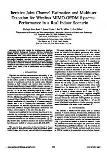
Figure 9: BER versus block length of G2-OSTBC 2 × 2 system at SNR = 30 dB and 𝑃𝑐 = 7.5% for 64 QAM.
100
BER
10−2
10−4
10−6 10
15
20 SNR (dB)
TDM: Oh = 32/256 DDST: iter 1; Pc = 9.25% MRST-PAT: iter 1; Pc = 9.25%; Oh = 4/256
25
30
TDM: Oh = 8/256 MRST-PAT: iter 2; Pc = 9.25%; Oh = 2/256
Figure 8: BER performance exhibited by the G2-OSTBC 2 × 2 system employing 64 QAM.
modified to such a degree that it is not possible to correctly recover it. Figure 7 shows the block error rate (BLER) performance using 16 QAM signals. In this case, BLER performance is used because it is a relevant measurement used for 3 GPP performance testing requirements, which determine the quality of the radio link. It corresponds to the ratio of the number of blocks received with at least one symbol error to the total number of blocks transmitted. It can be observed that at fixed BLER of 10−2 an advantage close to 1 dB was accomplished by MRST-PAT over DDST, both using one iteration and 𝑃𝑐 = 9.25% of the transmitted power. Figure 8 plots the BER performance for 64 QAM signals. Here, the advantage of the proposed MRST-PAT algorithm is more evident. An interesting analysis is that MRST-PAT (𝑂ℎ = 4/256 and one iteration) shows the same performance as TDM with 𝑂ℎ = 8/256. MRST-PAT (𝑂ℎ = 2/256 and two
iterations) approaches TDM with 𝑂ℎ = 8/256 in 0.5 dB, for SNR levels above 20 dB. Figure 9 plots the performance of 64 QAM G2-OSTBC versus the block length for the SNR fixed at 30 dB and 𝑃𝑐 = 7.5% for DDST and MRST-PAT. It can be seen from the figure that DDST for short block length yields poor results and for large block length (𝑁 = 8192 symbols) approaches TDM with eight pilots, while MRST-PAT for short block length yields good results and the performance increases proportionally as 𝑁 increases. It is important to note that DDST’s BER performance is highly sensitive to block length. In this scenario, we can appreciate the benefits and flexibility of the MRST-PAT structure, which exploits the presence of the known training symbols and the fact that the ST algorithm achieves a better channel estimate when the block length of the data transmitted is increased. Hence, the system user can change the parameters according to the requirements of block length or less rate loss, for example, fewer dedicated pilots or BER performance. Finally, it is important to analyze the BER performance versus the power fraction for the training signal, with the SNR fixed at 34 dB and 256 QAM signals. This SNR value is commonly required for this order of modulation. Figure 10 shows that DDST exhibits a poor BER performance for every value of power fraction allocated to the training signal. However, the BER performance exhibited by the MRST-PAT confirms that the proposed method overcomes the identifiability problem and makes the superimposed technique an attractive choice for multiamplitude QAM constellations. The same behavior is found at other SNR levels. For future research purposes, the proposed approach will be used with more sophisticated equalizers, such as that developed in [24, 25, 28], as well as with channel coders. The results obtained in this future research will allow determining the scenarios under which this new technique represents the best practical solution to be employed.
10
Mobile Information Systems [6] A. G. Orozco-Lugo, M. M. Lara, and D. C. McLernon, “Channel estimation using implicit training,” IEEE Transactions on Signal Processing, vol. 52, no. 1, pp. 240–254, 2004.
10−2
[7] M. Ghogho, D. McLernon, E. Alameda-Hernandez, and A. Swami, “Channel estimation and symbol detection for block transmission using data-dependent superimposed training,” IEEE Signal Processing Letters, vol. 12, no. 3, pp. 226–229, 2005.
BER
100
10−4
10−6
0
0.1
0.2
0.3
0.4
0.5
Pc
MRST-PAT: iter 2; Oh = 2/256 DDST: iter 2
Figure 10: BER performance versus power fraction for training exhibited by the G2-OSTBC 2 × 2 system at SNR = 34 dB employing 256 QAM.
7. Conclusion The iterative joint MRST-PAT MIMO detection and channel estimation technique introduced in this contribution deals effectively with DDST’s identifiability problem when higherorder modulation schemes are used. This leads to communication systems that achieve near-DDST performance for low-order symbols, such as BPSK and QPSK, and attain PAT (TDM) performance for higher-order symbols, such as 16 QAM or beyond, with minimal reduction in throughput and using a computationally efficient implementation. Since MRST-PAT is an iterative joint scheme, it can take advantage of both efforts, that is, using pilots by means of explicit training (PAT) and taking the benefit of the implicit training using the ST training signal in the transmitted block. Consequently, more flexible communication systems may be built according to different requirements and constraints. Similar results are expected for MIMO frequency-selective channels.
Competing Interests The authors declare that they have no competing interests.
References [1] H. Arslan and G. E. Bottomley, “Channel estimation in narrowband wireless communication systems,” Wireless Communications and Mobile Computing, vol. 1, no. 2, pp. 201–219, 2001. [2] J. K. Cavers, “An analysis of pilot symbol assisted modulation for Rayleigh fading channels [mobile radio],” IEEE Transactions on Vehicular Technology, vol. 40, no. 4, pp. 686–693, 1991. [3] L. Tong, B. M. Sadler, and M. Dong, “Pilot-assisted wireless transmissions: general model, design criteria, and signal processing,” IEEE Signal Processing Magazine, vol. 21, no. 6, pp. 12– 25, 2004. [4] S. Haykin and K. J. R. Liu, Handbook on Array Processing and Sensor Networks, Wiley-Blackwell, Hoboken, NJ, USA, 2010. [5] B. Farhang-Boroujeny, “Pilot-based channel identification: proposal for semi-blind identification of communication channels,” Electronics Letters, vol. 31, no. 13, pp. 1044–1046, 1995.
[8] E. Alameda-Hernandez, D. C. McLernon, A. G. OrozcoLugo, M. M. Lara, and M. Ghogho, “Frame/training sequence synchronization and DC-offset removal for (data-dependent) superimposed training based channel estimation,” IEEE Transactions on Signal Processing, vol. 55, no. 6, pp. 2557–2569, 2007. [9] E. Romero-Aguirre, R. Carrasco-Alvarez, R. Parra-Michel, A. G. Orozco-Lugo, and A. F. Mondrag´on-Torres, “Full-hardware architectures for data-dependent superimposed training channel estimation,” Journal of Signal Processing Systems, vol. 70, no. 2, pp. 105–123, 2013. [10] F. Mart´ın del, R. Campo, R. Perez-Andrade, and A. G. OrozcoLugo, “A system on a programmable chip architecture for data-dependent superimposed training channel estimation,” International Journal of Reconfigurable Computing, vol. 2009, Article ID 912301, 10 pages, 2009. [11] M. Ghogho and A. Swami, “Channel estimation for MIMO systems using data-dependent superimposed training,” in Proceedings of the 42nd Annual Allerton Conference on Communication, Control and Computing, Urbana Champaigh, Ill, USA, 2004. [12] M. Ghogho, D. McLernon, E. Alameda-Hernandez, and A. Swami, “SISO and MIMO channel estimation and symbol detection using data-dependent superimposed training,” in Proceedings of the IEEE International Conference on Acoustics, Speech, and Signal Processing (ICASSP ’05), vol. 3, pp. ii/461–iii/ 464, IEEE, March 2005. [13] S. M. A. Moosvi, D. C. McLernon, E. Alameda-Hernandez, A. G. Orozco-Lugo, and M. M. Lara, “A low complexity iterative channel estimation and equalisation scheme for (datadependent) superimposed training,” in Proceedings of the 14th European Signal Processing Conference (EUSIPCO ’06), pp. 1–5, Florence, Italy, September 2006. [14] X. Meng and J. K. Tugnait, “Semi-blind channel estimation and detection using superimposed training,” in Proceedings of the IEEE International Conference on Acoustics, Speech, and Signal Processing (ICASSP ’04), vol. 4, pp. iv-417–iv-420, IEEE, Montreal, Canada, May 2004. [15] R. Carrasco-Alvarez, R. Parra-Michel, A. G. Orozco-Lugo, and J. K. Tugnait, “Enhanced channel estimation using superimposed training based on universal basis expansion,” IEEE Transactions on Signal Processing, vol. 57, no. 3, pp. 1217–1222, 2009. [16] S. He, J. K. Tugnait, and X. Meng, “On superimposed training for MIMO channel estimation and symbol detection,” IEEE Transactions on Signal Processing, vol. 55, no. 6, pp. 3007–3021, 2007. [17] X. Meng, J. K. Tugnait, and S. He, “Iterative joint channel estimation and data detection using superimposed training: algorithms and performance analysis,” IEEE Transactions on Vehicular Technology, vol. 56, no. 4, pp. 1873–1880, 2007. [18] R. Dinis, N. Souto, J. Silva, A. Kumar, and A. Correia, “On the use of implicit pilots for channel estimation with OFDM modulations,” in Proceedings of the IEEE 66th Vehicular Technology Conference (VTC ’07), pp. 1077–1081, Baltimore, Md, USA, October 2007.
Mobile Information Systems [19] N. Chen and G. T. Zhou, “Superimposed training for OFDM: a peak-to-average power ratio analysis,” IEEE Transactions on Signal Processing, vol. 54, no. 6, pp. 2277–2287, 2006. [20] A. Goljahani, N. Benvenuto, S. Tomasin, and L. Vangelista, “Superimposed sequence versus pilot aided channel estimations for next generation DVB-T systems,” IEEE Transactions on Broadcasting, vol. 55, no. 1, pp. 140–144, 2009. [21] H. Zhang, X. Dai, D. Li, and S. Ye, “Linearly time-varying channel estimation and symbol detection for OFDMA uplink using superimposed training,” EURASIP Journal on Wireless Communications and Networking, vol. 2009, no. 1, Article ID 307375, 2009. [22] R. Carrasco-Alvarez, R. Parra-Michel, A. G. Orozco-Lugo, and J. K. Tugnait, “Time-varying channel estimation using two-dimensional channel orthogonalization and superimposed training,” IEEE Transactions on Signal Processing, vol. 60, no. 8, pp. 4439–4443, 2012. [23] X. Dai, H. Zhang, and D. Li, “Linearly time-varying channel estimation for MIMO/OFDM systems using superimposed training,” IEEE Transactions on Communications, vol. 58, no. 2, pp. 681–693, 2010. [24] R. Dinis, C.-T. Lam, and D. Falconer, “Joint frequencydomain equalization and channel estimation using superimposed pilots,” in Proceedings of the IEEE Wireless Communications and Networking Conference (WCNC ’08), pp. 447–452, IEEE, Las Vegas, Nev, USA, 2008. [25] N. Benvenuto, R. Dinis, D. Falconer, and S. Tomasin, “Single carrier modulation with nonlinear frequency domain equalization: an idea whose time has come—again,” Proceedings of the IEEE, vol. 98, no. 1, pp. 69–96, 2010. [26] T. Whitworth, M. Ghogho, and D. C. McLernon, “Data identifiability for data-dependent superimposed training,” in Proceedings of the IEEE International Conference on Communications (ICC ’07), pp. 2545–2550, IEEE, Glasgow, Scotland, June 2007. [27] T. Levanen, J. Talvitie, and M. Renfors, “Performance evaluation of time-multiplexed and data-dependent superimposed training based transmission with practical power amplifier model,” EURASIP Journal on Wireless Communications and Networking, vol. 2012, no. 1, article 49, 2012. [28] O. Longoria-Gandara, R. Parra-Michel, M. Bazdresch, and A. G. Orozco-Lugo, “Iterative mean removal superimposed training for SISO and MIMO channel estimation,” International Journal of Digital Multimedia Broadcasting, vol. 2008, Article ID 535269, 9 pages, 2008. [29] P. W. Wolniansky, G. J. Foschini, G. D. Golden, and R. A. Valenzuela, “V-BLAST: an architecture for realizing very high data rates over the rich-scattering wireless channel,” in Proceedings of the URSI International Symposium on Signals, Systems, and Electronics (ISSSE ’98), pp. 295–300, October 1998. [30] V. Tarokh, H. Jafarkhani, and A. R. Calderbank, “Space-time block codes from orthogonal designs,” IEEE Transactions on Information Theory, vol. 45, no. 5, pp. 1456–1467, 1999. [31] A. Gershman and N. Sidiropoulos, Space-Time Processing for MIMO Communications, John Wiley & Sons, New York, NY, USA, 2005. [32] M. Coldrey and P. Bohlin, “Training-based MIMO systems— part I: performance comparison,” IEEE Transactions on Signal Processing, vol. 55, no. 11, pp. 5464–5476, 2007. [33] J. K. Tugnait and W. Luo, “On channel estimation using superimposed training and first-order statistics,” IEEE Communications Letters, vol. 7, no. 9, pp. 413–415, 2003.
11 [34] S. M. Kay, Fundamentals of Statistical Signal Processing, Volume I: Estimation Theory, Prentice-Hall, Englewood Cliffs, NJ, USA, 1st edition, 1993. [35] M. Biguesh and A. B. Gershman, “Training-based MIMO channel estimation: a study of estimator tradeoffs and optimal training signals,” IEEE Transactions on Signal Processing, vol. 54, no. 3, pp. 884–893, 2006. [36] B. Hassibi and B. M. Hochwald, “How much training is needed in multiple-antenna wireless links?” IEEE Transactions on Information Theory, vol. 49, no. 4, pp. 951–963, 2003. [37] O. Longoria-Gandara, R. Parra-Michel, M. Bazdresch, and A. G. Orozco-Lugo, “Iterative mean removal superimposed training for frequency selective channel estimation,” in Proceedings of the International Conference on Wireless Communications, Networking and Mobile Computing (WiCOM ’08), pp. 1–5, Dalian, China, October 2008. [38] S. Y. Ronen, S. I. Bross, S. S. Shitz, and T. M. Duman, “Iterative channel estimation and decoding in turbo coded space-time systems,” European Transactions on Telecommunications, vol. 18, no. 7, pp. 719–734, 2007. [39] X. Huang, “Complementary properties of hadamard matrices,” in Proceedings of the International Conference on Communications, Circuits and Systems (ICCCAS ’06), vol. 1, pp. 588–592, Guilin, China, June 2006.
Journal of
Advances in
Industrial Engineering
Multimedia
Hindawi Publishing Corporation http://www.hindawi.com
The Scientific World Journal Volume 2014
Hindawi Publishing Corporation http://www.hindawi.com
Volume 2014
Applied Computational Intelligence and Soft Computing
International Journal of
Distributed Sensor Networks Hindawi Publishing Corporation http://www.hindawi.com
Volume 2014
Hindawi Publishing Corporation http://www.hindawi.com
Volume 2014
Hindawi Publishing Corporation http://www.hindawi.com
Volume 2014
Advances in
Fuzzy Systems Modelling & Simulation in Engineering Hindawi Publishing Corporation http://www.hindawi.com
Hindawi Publishing Corporation http://www.hindawi.com
Volume 2014
Volume 2014
Submit your manuscripts at http://www.hindawi.com
Journal of
Computer Networks and Communications
Advances in
Artificial Intelligence Hindawi Publishing Corporation http://www.hindawi.com
Hindawi Publishing Corporation http://www.hindawi.com
Volume 2014
International Journal of
Biomedical Imaging
Volume 2014
Advances in
Artificial Neural Systems
International Journal of
Computer Engineering
Computer Games Technology
Hindawi Publishing Corporation http://www.hindawi.com
Hindawi Publishing Corporation http://www.hindawi.com
Advances in
Volume 2014
Advances in
Software Engineering Volume 2014
Hindawi Publishing Corporation http://www.hindawi.com
Volume 2014
Hindawi Publishing Corporation http://www.hindawi.com
Volume 2014
Hindawi Publishing Corporation http://www.hindawi.com
Volume 2014
International Journal of
Reconfigurable Computing
Robotics Hindawi Publishing Corporation http://www.hindawi.com
Computational Intelligence and Neuroscience
Advances in
Human-Computer Interaction
Journal of
Volume 2014
Hindawi Publishing Corporation http://www.hindawi.com
Volume 2014
Hindawi Publishing Corporation http://www.hindawi.com
Journal of
Electrical and Computer Engineering Volume 2014
Hindawi Publishing Corporation http://www.hindawi.com
Volume 2014
Hindawi Publishing Corporation http://www.hindawi.com
Volume 2014