A very recent work [1] considers joint channel estimation and multiuser ...... output APP module for iterative decoding of concatenated codes,â IEEE. Commun.
IEEE TRANSACTIONS ON WIRELESS COMMUNICATIONS, VOL. 7, NO. 11, NOVEMBER 2008
4719
Joint Twofold-Iterative Channel Estimation and Multiuser Detection for MIMO-OFDM Systems Pierluigi Salvo Rossi and Ralf R. M¨uller, Senior Member, IEEE
Abstract—This paper presents an iterative receiver for Multiple-Input Multiple-Output (MIMO) Orthogonal Frequency Division Multiplexing (OFDM) systems over time-variant wireless channels. The receiver performs joint decoding, channel estimation, and multiuser detection, with soft information iteratively provided by the single-user decoders. Time-variance is effectively taken into account exploiting the properties of the Discrete Prolate Spheroidal (DPS) sequences, being the bandlimited sequences with maximum energy concentration in time. Turbo codes are used for each transmit antenna, thus the receiver presents an iterative structure also in the single-user case. Simulation results for the performance are presented in terms of Bit Error Rate (BER) and Normalized Mean Square Error (NMSE) vs Signalto-Noise Ratio (SNR). The effects of the number of external and internal iterations as well as the number of pilots on the performance of the system are investigated. Index Terms—Channel estimation, discrete prolate spheroidal sequences, iterative decoding, MIMO channels, multiuser detection, OFDM systems, turbo codes.
I. I NTRODUCTION
W
IRELESS broadband communications for multimedia applications with quality comparable to wireline technologies are among the most required services in the modern society of information. Furthermore, system design is even more challenging due to the intrinsic problems affecting the radio channel and also to mobility requirements up to vehicular speeds. Multiple-Input Multiple-Output (MIMO) systems, obtained by means of multiple antennas at both transmitter and receiver sides, have shown to provide diversity and capacity gains [11], [29]. Capacity gain is particularly interesting when focusing on high-data-rate system design, with MIMO systems increasing capacity by a factor of the minimum number of transmit and receive antennas. Orthogonal Frequency Division Multiplexing (OFDM) is a technique for high-data-rate transmissions adopted in several standards [11], [29]. Compared to single-carrier transmissions, OFDM simplifies channel equalization due to conversion of a dispersive channel into a set of parallel memoryless subchannels. Combinations of OFDM with MIMO technology were shown to mitigate inter-symbol interference and enhance system capacity simultaneously, thus
Manuscript received August 27, 2007; revised February 4, 2008 and July 8, 2008; accepted October 18, 2008. The associate editor coordinating the review process of this paper and approving it for publication was D. Huang. This work has been supported by the Research Council of Norway under the project “WILATI - WIreless LANs with high Throughput in Interferencelimited environments” within the NORDITE framework (grant 172239/S10). The authors are with the Department of Electronics and Telecommunications, Norwegian University of Science and Technology (NTNU), O.S. Bragstads plass 2B, 7491 Trondheim, Norway (e-mail: {salvoros, mueller}@iet.ntnu.no). Digital Object Identifier 10.1109/T-WC.2008.070953
improving the overall system performance [14], [27]. MIMOOFDM systems are the main candidates for enabling wireless high-data-rate communications. Multiuser detection [31], i.e. the ability to exploit at the receiver the structure of Multiple Access Interference (MAI), is a key issue to provide the required services. Iterative (turbo) multiuser receivers achieve excellent performance with contained complexity, thus candidating as the main technique for next generation systems [2], [6], [7], [25], [32]. Multiuser decoding is decoupled into separate problems, i.e. multiuser detection and single-user decoding, iteratively exchanging their results with each other via soft information. Components of the receiver are sometimes referred to as Soft-Input SoftOutput (SISO) blocks [4]. As for multiuser detection, it has been shown that Parallel Interference Cancellation (PIC) followed by Minimum Mean Square Error (MMSE) filtering performs less than 1 dB away from optimum belief propagation [7]. Iterative receivers for MIMO-OFDM systems have been presented in [12], [15], [17], although channel estimation has not benefited of the iterative structure. In other scenarios [16], [23], [24], [34] channel estimation has been included in the iterative structure, improving the system performance. Many different approaches has been proposed for channel estimation, and basis expansion models techniques [10] have resulted very simple and powerful. Among them, Slepian-basis expansion models [33] have been shown to outperform more classical Fourier-basis expansion models [13]. Time variation of the channel, becoming crucial when high mobility is required, is taken into account efficiently and accurately by exploiting the properties of the Discrete Prolate Spheroidal (DPS) sequences [26], [33]. A very recent work [1] considers joint channel estimation and multiuser detection in MIMO-OFDM systems combined with the use of turbo codes. Turbo codes [5], [18] represent a class of near-capacity channel codes with sustainable complexity both at transmitter and receiver sides. Very good performance with turbo codes over fading channels has been obtained with iterative receivers performing turbo decoding and pilot-assisted channel estimation [30]. This paper proposes an iterative receiver for MIMO-OFDM systems making use of turbo codes and performing joint time-variant channel estimation and multiuser detection. It is compared with an otherwise identical system using convolutional codes [24] as well as with the system proposed in [1]. Performance of the systems are studied via Bit Error Rate (BER) vs Signal-to-Noise Ratio (SNR). The paper is organized as follows: the mathematical model for the considered MIMOOFDM system is described in Section II; in Section III we
c 2008 IEEE 1536-1276/08$25.00 �
Authorized licensed use limited to: Norges Teknisk-Naturvitenskapelige Universitet. Downloaded on December 3, 2008 at 10:46 from IEEE Xplore. Restrictions apply.
4720
Fig. 1.
IEEE TRANSACTIONS ON WIRELESS COMMUNICATIONS, VOL. 7, NO. 11, NOVEMBER 2008
Block diagram for the Transmitter.
A. Transmitter
Fig. 2.
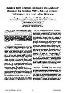
Pilot placement for S = 11 and Sp = 3.
develop the structure of the iterative receiver; Section IV shows and compares the performance obtained via numerical simulations; concluding remarks are given in Section V. Notation - Column vectors are denoted with lower-case bold letters, with an denoting the nth element of vector a; matrices are denoted with upper-case bold letters, with An,m denoting the (n, m)th element of matrix A; diag(a) denotes a diagonal matrix whose main diagonal is a; IN is (n) the N ×N identity matrix; iN denotes the nth column of IN ; eN denotes a vector of length N whose elements are 1; E{.}, (.)∗ , (.)T and (.)H denote expectation, conjugate, transpose and conjugate transpose operators, respectively; δn,m is the Kronecker delta; ⊗ denotes the Kronecker matrix product; �a� denotes the smallest integer value greater than or equal to a; j is the imaginary unit; N (μ, σ 2 ) denotes a normal distribution with mean μ and variance σ 2 ; NC (μ, Σ) denotes a circular symmetric complex normal distribution with mean vector μ and covariance matrix Σ; the symbol ∼ means “distributed as”.
II. S YSTEM M ODEL We consider a MIMO-OFDM system with K transmit antennas, N receive antennas, and M subcarriers. Each transmit antenna is assumed to send an independent (from other transmit antennas) data stream, thus we consider equivalent the terms “user” and “transmit antenna”. The scenario corresponds to the case in which K users are provided with one single transmit antenna as well as to the case in which one single user is provided with K transmit antennas and its data stream is parallelized in K independent data streams, or intermediate configurations in which different disjoint subsets of the K transmit antennas belong to different users.
The transmission is frame oriented. The block diagram for the transmitter at the generic transmit antenna is shown in Fig. 1. The bit stream is divided in groups of Lb source bits and each group is encoded via a Parallelly Concatenated Convolutional Encoder (PCCE) followed by an interleaver, then Lp pilot bits are inserted to produce a frame of L code bits. The bits of the frame are mapped into symbols via Binary Phase Shift Keying (BPSK) modulation [20], thus in the following we use the term frame to denote both the bits and the BPSK symbols. Each frame conveys Lb source bits at rate Lb /L. The frame is divided into S = L/M blocks, and each block gives rise to an OFDM block of M symbols to be transmitted on the wireless channel via the M subcarriers. We assume that both L and Lp are integer multiples of M , thus in each frame we have Sp = Lp /M pilot OFDM blocks and S−Sp data OFDM blocks. Optimal pilot placement [28] falls beyond the scope of this paper, and we simply assume that pilot OFDM blocks are distributed within the frame according to the set of indexes ��
(2s − 1)S 2Sp
��Sp , s=1
resulting in a regular placement of pilot symbols. Fig. 2 shows an example for S = 11 and Sp = 3. Data and pilot symbols are represented by white and black boxes, respectively. The block diagram for the singleuser encoder is shown in the left part of Fig. 3. Source bits are encoded via a classical PCCE composed of two rate-1/2 Recursive Systematic Convolutional Encoders (RSCE’s) and an internal interleaver. Puncturing is used to keep the overall rate equal to 1/2; more specifically odd (resp. even) parity check bits are kept (resp. discarded) from RSCE-1 and even (resp. odd) parity check bits are kept (resp. discarded) from RSCE-2. Encoded bit are serialized and then interleaved via an external interleaver. Three different groups are found among the encoded bits: (i) (ii) (iii)
the systematic part, i.e. the original source bits; the parity-1 part, i.e. the parity check bits kept from RSCE-1; the parity-2 part, i.e. the parity check bits kept from RSCE-2.
Authorized licensed use limited to: Norges Teknisk-Naturvitenskapelige Universitet. Downloaded on December 3, 2008 at 10:46 from IEEE Xplore. Restrictions apply.
¨ SALVO ROSSI and MULLER: JOINT TWOFOLD-ITERATIVE CHANNEL ESTIMATION AND MULTIUSER DETECTION FOR MIMO-OFDM SYSTEMS
4721
Fig. 3. Block diagram for the singleuser encoder (on the left) and decoder (on the right). Dotted lines represent the feedback to the MUD and to the TVCE.
B. Signal Model In the following, for the generic frame, bk [�] and ck [�] denote the �th source bit and the �th code bit (including pilots) to be transmitted by the kth transmit antenna; xk [m, s] denotes the (Frequency Domain) symbol transmitted by the kth transmit antenna on the mth subcarrier during transmission of the sth OFDM block (yk [m, s] corresponds in Time Domain); Hn,k [m, s] denotes the (Frequency Domain) channel coefficient between the kth transmit antenna and the nth receive antenna on the mth subcarrier during transmission of the sth OFDM block; wn [m, s] denotes the (Frequency Domain) additive noise at the nth receive antenna on the mth subcarrier during transmission of the sth OFDM block; rn [m, s] denotes the (Frequency Domain) received signal at the nth receive antenna on the mth subcarrier during transmission of the sth OFDM block (qn [m, s] corresponds in Time Domain). We denote the transmitted vector, the channel matrix, the noise vector, and the received vector as x[m, s] = H[m, s] = w[m, s] = r[m, s] =
T
(x [m, s], . . . , xK [m, s]) , ⎛1 ⎞ H1,1 [m, s] . . . H1,K [m, s] ⎜ ⎟ .. .. .. ⎝ ⎠ , . . . HN,1 [m, s] . . . HN,K [m, s] T
2 (w1 [m, s], . . . , wN [m, s]) ∼ NC (0, σw IN ) ,
(r1 [m, s], . . . , rN [m, s])
T
,
and assume that the length of the cyclic prefix (Lcp) exceeds the channel delay spread, then the discrete-time model for the received signal is r[m, s] = H[m, s]x[m, s] + w[m, s] .
(1)
Also, we denote the channel vector from the kth transmit antenna as (k)
h(k) [m, s] = H[m, s]iK . It is worth noticing that m and s represent frequencyvariation and time-variation, respectively. The channel is considered time-variant meaning that it does not remain constant within the frame: different OFDM blocks experience different
attenuation. We also assume that the channel stays constant for the duration of each OFDM block, and subcarriers experience independent attenuations, corresponding to the case when their distance exceeds the coherence bandwidth of the channel. C. Receiver Transmissions from the various transmit antennas combine at each receive antenna and are processed according to the receiver model shown in Fig. 4. OFDM robustness to time asynchrony allows to neglect synchronization problems among transmit antennas as long as their asynchrony does not exceed the duration of the cyclic prefix. Each OFDM block is demodulated and sent to the iterative decoder, composed of MultiUser Detector (MUD), Single-User Decoder Bank (SUDB), and Time-Variant Channel Estimator (TVCE). It performs three tasks: (i) Multiuser Detection - processing realized via PIC and MMSE filtering [16], [32], [34]. • Input: received signal from the demodulator, code extrinsic information from the SUDB, channel estimates from the TVCE; • Output: symbol extrinsic information to the SUDB. (ii) Single User Decoding - processing realized via the turbo-decoding algorithm [5], [18]. • Input: symbol extrinsic information from the MUD; • Output: code extrinsic information to the MUD, code a-posteriori information to the TVCE, source a-posteriori information as final output. (iii) Channel Estimation - processing realized via Slepian Basis Expansion (SBE) and Linear MMSE (LMMSE) estimation [33], [34]. • Input: received data from the demodulator, code a-posteriori information from the SUDB; • Output: channel estimates to the MUD. The block diagram for the singleuser decoder is shown in the right part of Fig. 3.
Authorized licensed use limited to: Norges Teknisk-Naturvitenskapelige Universitet. Downloaded on December 3, 2008 at 10:46 from IEEE Xplore. Restrictions apply.
4722
Fig. 4.
IEEE TRANSACTIONS ON WIRELESS COMMUNICATIONS, VOL. 7, NO. 11, NOVEMBER 2008
Block diagram for the Receiver.
The receiver is twofold iterative because two kinds of iterations can be found: (i) external iterations referring to the feedback from the SUDB to the MUD and to the TVCE, as shown in Fig. 4; (ii) internal iterations referring to the feedback inside the SUDB for turbo decoding of each user, as shown in Fig. 3. III. I TERATIVE R ECEIVER Both the MUD and the SUDB exchange extrinsic soft information on symbols xk . We denote x˜k the information passing from the SUDB to the MUD, and z˜k the information passing from the MUD to the SUDB. The SUDB also provides a-posteriori soft information on symbol xk , denoted xˆk , to the TVCE, and a-posteriori soft information on the source bit, denoted dk . The TVCE provides channel coefficient estimates, ˆ n,k . denoted H It is worth noticing that {z˜k [1], . . . , z˜k [L]} are externaldeinterleaved before being passed to the SUDB, while {x˜k [1], . . . , x˜k [L]} and {xˆk [1], . . . , xˆk [L]} are externalinterleaved before being passed to the MUD and to the TVCE, respectively. In the following, in order to keep notation simple, we do not introduce different notations to explicitly distinguish external-interleaved and external-deinterleaved symbols, and leave the meaning to be evinced from the context.
˜ from the SUDB and H from the The PIC block receives x (k) ˜ − x˜k iK , the residual term from ˜ (k) = x TVCE. Denoting x the interference cancellation is computed for each transmit antenna as ˜ (k) . r˜(k) = r − H x
(2)
The residual term is then processed with an MMSE filter, in order to reduce further the effects of noise and MAI, giving the extrinsic-based soft information
−1 (k)H −1 2 H H H + σw V(k) H H r˜(k) iK z˜k = , (3)
−1 (k)H 2 V −1 Hh H H H + σw iK H (k) (k) being V(k)
�� �� �H � ˜ (k) ˜ (k) x − x x−x
=
E
=
diag(1 − |˜ x1 |2 , . . . , 1 − |˜ xk−1 |2 , 1, xK |2 ) . 1 − |˜ xk+1 |2 , . . . , 1 − |˜
It is worth noticing that (3) is usually denoted as the output of a “conditional” unbiased MMSE filter, as it is obtained on the basis of the soft estimates for each single symbol, for each iteration, for each subcarrier, for each OFDM block. B. Singleuser Decoding
A. Multiuser Detection As previously said, the considered MUD performs PIC and MMSE filtering. More precisely, the received signals (1) are processed separately for each subcarrier and for each OFDM block. We omit the indexes m and s to simplify notation. Also, we assume that the receiver behaves as if perfect knowledge of the channel coefficients is available, while in practice estimates from the TVCE are used.
After collecting {˜ zk [1], . . . , z˜k [L]}, each transmit antenna can be decoded independently. It is worth noticing that z˜k [�] has been transmitted on the mth subcarrier during the sth OFDM block if � = (s − 1)M + m. The output of the MUD [32], used by the kth SISO singleuser decoder for the kth transmit antenna, is modeled as z˜k = μk xk + vk ,
Authorized licensed use limited to: Norges Teknisk-Naturvitenskapelige Universitet. Downloaded on December 3, 2008 at 10:46 from IEEE Xplore. Restrictions apply.
¨ SALVO ROSSI and MULLER: JOINT TWOFOLD-ITERATIVE CHANNEL ESTIMATION AND MULTIUSER DETECTION FOR MIMO-OFDM SYSTEMS
with vk ∼ N (0, ηk2 ), where μk
= 1,
ηk2
=
respectively, with Q being the number of states for the code. The initialization of the forward variables takes into account that both RSCE-1 and RSCE-2 start in state 1. The initialization of the backward variables takes into account that (due to the insertion of appropriate tail bits to the block of source bits within the frame) RSCE-1 stops in state 1, while RSCE-2 stops in an arbitrary state because of the internal interleaver. Also, the algorithm has been implemented in the logdomain [22], where the logarithm of a sum of exponentials is computed exploiting the Jacobian logarithm
� � log eδ1 + eδ2 = max(δ1 , δ2 ) + log 1 + e−|δ2 −δ1 | . C. Channel Estimation We consider a channel with maximum normalized Doppler (D) (D) (D) spread νmax , i.e. the interval [−νmax , +νmax ] is the support 1 The
encoder.
of the Doppler Spectrum for the mth subcarrier on the link from kth transmit antenna to nth receive antenna
1 .
−1 (k)H 2 V −1 Hh H H H + σw iK H (k) (k)
We omit the index k to simplify notation. The frame {˜ z [1], . . . , z˜[L]} is decoded with a turbo-decoding algorithm that iteratively applies the Bahl-Cocke-Jelinek-Raviv (BCJR) [3] algorithm to the single RSCEs composing the PCCE. The algorithm we have considered is the classical turbodecoding algorithm [5], [18]. According to the decoder for the generic user shown in Fig. 3, the frame {z[1], . . . , z[L]} is decomposed in the systematic, parity-1, and parity-2 parts: • systematic part and parity-1 part enter the decoder BCJR-1 associated to RSCE-1; • internally-interleaved systematic part and parity-2 part enter the decoder BCJR-2 associated to RSCE-2; • BCJR-1 outputs a-posteriori information fed back to the TCVE, and extrinsic information fed back to the MUD and to BCJR-2; extrinsic information to BCJR-2 is internally-interleaved; • BCJR-2 outputs a-posteriori information fed back to the TVCE, and extrinsic information fed back to the MUD and to BCJR-1; a-posteriori and both extrinsic informations are internally-deinterleaved; • estimates on source bits are taken from a-posteriori information out of BCJR-1. The BCJR algorithm [3], [18] is a very well known algorithm to compute soft information in SISO blocks, that exploits the trellis representation of the single code. It is worth mentioning that, denoting αt (i) (resp. βt (i)) the forward (resp. backward) variable at the end of the tth transition1 in the ith state, we have used the following initializations for RSCE-1 and RSCE-2 � � α0 (i) = δi,1 α0 (i) = δi,1 , , βT (j) = δj,1 βT (j) = 1/Q
tth transition corresponds to the tth information bit entering the
4723
(D)
Hn,k (m, ν) =
+∞ �
Hn,k (m, s) exp(−j2πνs) .
s=−∞
Referring to a SBE [33], [34], channel coefficients are expressed as Hn,k (m, s) ≈
I �
(4)
ψn,k [m, i]ui [s] ,
i=1
where ψn,k [m, i] is the ith SBE coefficient for the link between kth transmit antenna and nth receive antenna on mth subcarrier, ui [s] is the sth sample of the ith DPS sequence defined as the solution to S �
(D) (D) (D) 2νmax sinc 2νmax (s� − s) ui [s� ] = λi (νmax , S)ui [s] ,
s� =1
� � (D) and SD ≤ I ≤ S, being SD = 2νmax S + 1 the approximate (D)
signal space dimension. Also, λi (νmax , S) is the eigenvalue coupled with the eigenfunction ui [s]. In the following u[s] = λ =
T
(u1 [s], . . . , uI [s]) T
(λ1 , . . . , λI )
,
,
denote the vector collecting the values of the DPS sequences for a given time, and the vector collecting the corresponding eigenvalues. The SBE makes use of an orthogonal basis based on DPS sequences, that have shown to be the bandlimited sequences simultaneously most concentrated in a finite time interval [26]. Advantage of using the SBE is twofold: (i) (ii)
low complexity - the reduction of the space dimension means less coefficients to be estimated; high accuracy - no assumption on the stochastic model for the channel is needed, but only knowledge of the maximum normalized Doppler spread.
Maximum normalized Doppler spread is basically determined by the maximum permitted velocity, thus it is worth noticing that the model does not need exact knowledge either of the channel statistics or of the effective Doppler. The signal model for channel estimations is r[m] = Ξ[m]ψ[m] + w[m] , where for a given subcarrier, �T � , r[m] = r T [m, 1], . . . , r T [m, S] � T �T T w[m] = w [m, 1], . . . , w [m, S] , denote the collection in time of received symbols and corresponding noise contribution; ξ[m, s] =
x[m, s] ⊗ u[s] ,
Ξ[m, s] =
IN ⊗ ξ T [m, s] , �T � T , Ξ [m, 1], . . . , ΞT [m, S]
Ξ[m] =
Authorized licensed use limited to: Norges Teknisk-Naturvitenskapelige Universitet. Downloaded on December 3, 2008 at 10:46 from IEEE Xplore. Restrictions apply.
4724
IEEE TRANSACTIONS ON WIRELESS COMMUNICATIONS, VOL. 7, NO. 11, NOVEMBER 2008
appropriately collect in time transmitted symbols and basis functions; ψn,k [m] = ψn [m] = ψ[m] =
T
(ψn,k [m, 1], . . . , ψn,k [m, I]) � T �T T ψn,1 [m], . . . , ψn,K [m] , � T �T T ψ1 [m], . . . , ψN [m] ,
•
, •
take into account for SBE coefficients, collecting with respect to transmit antennas, receive antennas, and time, respectively. We omit the index m to simplify notation. Restricting our attention to linear channel estimators, we have the following estimator [24]
−1 ˆ H ΞC ˆH + Δ ˆ ψΞ r, = Cψ Ξ
−1 ˆ + C −1 ˆ H Δ−1 r , ˆ H Δ−1 Ξ Ξ = Ξ ψ
ψˆ
•
•
(5)
to be used in (4), where Cψ
=
λψ = ˆ = Ξ
� � E ψψ H = eN K ⊗ λ ,
1 (D)
2νmax
E {Ξ} ,
Δ =
2 Θ + σw ISN ,
Θ =
diag(ϑ ⊗ eN ) ,
ϑ =
(ϑ1 , . . . , ϑS ) I � K � λi
ϑs
=
diag (λψ ) ,
T
(D) i=1 k=1 2νmax
, � � xk [m, s]|2 . |ui [s]|2 1 − |ˆ
The expectation for the transmitted symbols is made using a-posteriori soft estimates from the SUDB. It is worth noticing that the matrix inversion lemma in (5) replaces the inversion of an SN × SN matrix with the inversion of an N KI × N KI matrix, saving computations (D) when K < 1/(2νmax ). Also it is worth noticing that both Cψ and Δ are diagonal, thus their inversion is not computationally prohibitive. Performance of channel estimation is evaluated via the Normalized Mean Square Error (NMSE) δH =
ˆ n,k [m, s]|2 } E{|Hn,k [m, s] − H . E{|Hn,k [m, s]|2 }
D. Twofold-Iterative Algorithm Both the number of external iterations (Jext ) and the number of internal iterations (Jint ) affect the performance of the receiver. For each external iteration, different numbers of internal iterations can be executed. In the following (Jext ; Jint ) will denote a receiver which perform Jext external iterations, and for each external iteration BCJR-1 and BCJR-2 are run iteratively Jint times, and then BCJR-1 is run one more time. More specifically, the scheduling of the algorithm is shown in Fig. 5.
•
Fig. 5.
p = pilots(r); % select pilots from received data xˆs = 0; x ˆ1 = 0; x ˆ2 = 0; % initialize a-posteriori data estimates for TVCE x˜ = 0; x ˜1 = 0; x ˜2 = 0; % initialize extrinsic data estimates for MUD repeat Jext times % external loop ˆ = TVCE(p, Πext (ˆ – H x)); % perform channel estimation ˆ Πext (˜ x)); – z˜ = MUD(r, H, % perform multiuser detection z )); – (˜ zs , z˜1 , z˜2 ) = ungroup(Π−1 ext (˜ % select systematic, parity-1 and parity-2 components – repeat (Jint ) times % internal loop ∗ (˜ xs , x ˜1 , x ˆs , x ˆ1 ) = BCJR(˜ zs , z˜1 , Π−1 xs )); int (˜ % perform singleuser decoding with first decoder ˜2 , x ˆs , x ˆ2 ) = BCJR(Πint (˜ zs ), z˜2 , Πint (˜ xs )); ∗ (˜ xs , x % perform singleuser decoding with second decoder ˜1 , x ˆs , x ˆ1 ) = BCJR(˜ zs , z˜1 , Π−1 xs )); – (˜ xs , x int (˜ % perform singleuser decoding with first decoder ˆ1 , x ˆ2 ); x ˜ = group(˜ xs , x ˜1 , x˜2 ); – x ˆ = group(ˆ xs , x % combine systematic, parity-1 and parity-2 components d = demod(˜ xs ); % final estimate Scheduling of the twofold-iterative algorithm.
IV. S IMULATION R ESULTS Numerical performance in terms of BER-vs-SNR and NMSE-vs-SNR have been obtained for various systems. The SNR is defined classically as the ratio between the “energy per source bit” and the “one-sided noise power spectral density”. Unless otherwise indicated, results shown here refer to systems with K = 2 transmit antennas and N = 2 receive antennas (2 × 2 systems), M = 32 subcarriers and S = 128 OFDM blocks per frame thus corresponding to L = 4096 code bits per frame (per transmit antenna). Excluding pilots, code bits are generated at rate 1/2 via a PCCE composed by 2 identical rate-1/2 RSCEs with generators (7, 5)8 and a random internal interleaver. The external interleaver is also random. Two tail bits enforce the final state of RSCE-1 into 1, thus each antenna transmits Lb = M (S − Sp )/2 − 2 source bits per frame. Results refer to synthetic channel coefficients simulating time-variant channels with Rayleigh fading according to Jakes’model [21], [33], [35]. Channel coefficients for each transmit-receive antenna pair and for each subcarrier have been independently generated according to a model with 15
Authorized licensed use limited to: Norges Teknisk-Naturvitenskapelige Universitet. Downloaded on December 3, 2008 at 10:46 from IEEE Xplore. Restrictions apply.
¨ SALVO ROSSI and MULLER: JOINT TWOFOLD-ITERATIVE CHANNEL ESTIMATION AND MULTIUSER DETECTION FOR MIMO-OFDM SYSTEMS
0
respectively, when Jext = 1, 3, 5, 7, 10. Performance improves for each external iteration. The gain with respect to the previous iteration is decreasing with the number of iterations. For this case, numerical simulations showed that convergence is almost reached after 10 external iterations. For very low SNR the iterative procedure degrades the performance, clearly shown with the NMSE. Fig. 6 also shows the performance of the analogous MIMOOFDM system with joint time-variant channel estimation and multiuser detection using convolutional codes for channel coding of the single users, described in [24] and referred to as CC, as well the performance of the MIMO-OFDM and making use of turbo codes, described in [1] and referred to as AH.
10
−1
10
−2
10
−3
BER
10
−4
10
J
=1
J
=3
ext
−5
10
ext
Jext=5
−6
10
Jext=7 Jext=10
−7
10
CC AH
−8
10
4
4.5
5
5.5
6
6.5
7
7.5
8
B. Effect of the number of internal iterations
SNR (dB) Fig. 6. BER-vs-SNR. Simulation results for a 2 × 2 system with M = 32, (D) S = 128, Sp = 12, Jint = 3, νmax = 0.005. Dashed lines refer to systems considered for comparison. 0
10
NMSE
−1
10
J
=1
ext
Jext=3 Jext=5
−2
10
J
=7
J
=10
ext ext
4
4.5
4725
5
5.5
6
6.5
7
7.5
8
SNR (dB) Fig. 7. NMSE-vs-SNR. Simulation results for a 2 × 2 system with M = 32, (D) S = 128, Sp = 12, Jint = 3, νmax = 0.005.
interfering paths and maximum normalized Doppler frequency (D) νmax = 0.005. The signal space dimension is then reduced from S = 128 to SD = 2, and I = 5 coefficients have been used for each SBE. Performance of the system are analyzed with respect to the choice of the number of external iterations (Jext ), the number of internal iterations (Jint ), and the number of pilots (Sp ). A. Effect of the number of external iterations We assume that for each external iteration the number of internal iterations is Jint = 3. We also assume Sp = 12 pilot OFDM blocks, thus each antenna transmits Lb = 1854 source bits per frame, generating 3712 code bits. Increasing the number of external iterations (Jext ) produces the wellknown turbo effect that has been extensively analyzed in various turbo receivers [6], [7], [16], [23], [24], [32], [34]. Figs. 6 and 7 show the BER and NMSE performance,
Again we assume Sp = 12 pilot OFDM blocks, thus each antenna transmits Lb = 1854 source bits per frame, generating 3712 code bits. Different (Jint ; Jext )-combinations have been analyzed in order to understand the role of both the kinds of iterations. For each given Jint , the value of Jext has been decreased but in order to (almost) achieve convergence. Figs. 8 and 9 show the BER and NMSE performance, respectively, in the following cases: • (Jint = 1 ; Jext = 30); • (Jint = 2 ; Jext = 15); • (Jint = 3 ; Jext = 10); • (Jint = 4 ; Jext = 8); • (Jint = 5 ; Jext = 6). It is apparent how for relatively large SNR the performance are very similar, and that increasing the number of internal iterations (Jint ) allows to decrease the number of external iterations (Jext ). It is interesting to notice that for low SNR, among the (Jint , Jext )-combinations presenting same performance at high SNR, those with larger Jint (and smaller Jext ) perform better. We mean that even if for large SNR differences in performance tend to vanish, the number of internal iterations discriminates significantly the performance at low SNR (in the “waterfall region”). Also, denoting OM , OS , OC , and OR the number of operations executed by the MUD, the BCJR, the TVCE, and the whole receiver, respectively, then we have OR = Jext (OM + OC + 2KOS Jint ). It is apparent that increasing Jint has effect only on the third term, while increasing Jext has effect also on the first and the second, that are the most expensive (requiring matrix inversion). From a computational complexity point of view larger number of internal iterations (Jint ) is to be preferred. We can affirm that increasing the number of internal iterations has a twofold advantage: (i) it gives better performance at low SNR; (ii) it reduces the computational complexity. C. Effect of pilot percentage Large number of iterations would require fast processors at receiver side, thus containing the number of both internal and
Authorized licensed use limited to: Norges Teknisk-Naturvitenskapelige Universitet. Downloaded on December 3, 2008 at 10:46 from IEEE Xplore. Restrictions apply.
4726
IEEE TRANSACTIONS ON WIRELESS COMMUNICATIONS, VOL. 7, NO. 11, NOVEMBER 2008
0
0
10
10
−1
−1
10
10
−2
−2
10
10
−3
−3
10
BER
BER
10
−4
10
−4
10
−5
−5
10
10
J =1 ; J int
−6
=30
ext
−6
Jint=2 ; Jext=15
10
10
PCSI PSR=5% PSR=7% PSR=9% PSR=12%
Jint=3 ; Jext=10 −7
10
Jint=5 ; Jext=6
−8
10
−7
Jint=4 ; Jext=8
10
4
4.5
5
−8
5.5
6
6.5
7
7.5
10
8
4
4.5
5
5.5
6
6.5
7
7.5
8
SNR (dB)
SNR (dB) Fig. 8. BER-vs-SNR. Simulation results for a 2 × 2 system with M = 32, (D) S = 128, Sp = 12, νmax = 0.005.
Fig. 10. BER-vs-SNR. Simulation results for a 2 × 2 system with M = 32, (D) S = 128, Jint = 3, Jext = 3, νmax = 0.005. Dashed line refers to the case with perfect channel-state information at the receiver.
0
10
0
10
−1
NMSE
NMSE
−1
10
J =1 ; J
=30
J =2 ; J
=15
int int
10
ext ext
Jint=3 ; Jext=10
−2
Jint=4 ; Jext=8
10
4
4.5
5
PSR=5% PSR=7% PSR=9% PSR=12%
−2
10
Jint=5 ; Jext=6 5.5
6
6.5
7
7.5
8
SNR (dB)
4
4.5
5
5.5
6
6.5
7
7.5
8
SNR (dB) Fig. 9. NMSE-vs-SNR. Simulation results for a 2 × 2 system with M = 32, (D) S = 128, Sp = 12, νmax = 0.005.
external iterations could be a practical constraint. We assume here a system with (Jint = 3 ; Jext = 3). From the sampling theorem point of view, the normalized Doppler bandwidth determines the minimum rate of pilots that is needed in order to perform channel estimation [28]. Numerical simulations showed that oversampling, i.e. increasing the number of pilots, allows to decrease the SNR value for which the receiver experiences the turbo effect, meaning better performance for low SNR. We call Pilot-to-Symbol Ratio (PSR) the ratio of the number of pilots with respect to the whole symbols in a frame, i.e. δP = Sp /S. Design strategies for pilot percentage allocation have been proposed for single antenna systems with convolutional coding and turbo equalization [19]. Figs. 10 and 11 show the BER and NMSE performance, respectively, when Sp = 6, 9, 12, 15 corresponding to • Lb = 1950 source bits and 3904 code bits per frame; • Lb = 1902 source bits and 3808 code bits per frame;
Fig. 11. NMSE-vs-SNR. Simulation results for a 2×2 system with M = 32, (D) S = 128, Jint = 3, Jext = 3, νmax = 0.005.
• •
Lb = 1854 source bits and 3712 code bits per frame; Lb = 1806 source bits and 3616 code bits per frame;
respectively, thus PSR ≈ 5%, 7%, 9%, 12%, corresponding to data rates of 95%, 93%, 91%, 88%, respectively. It is apparent how the effect of increasing the number of pilots is a significant improvement in performance for low SNR. Analogously to the turbo effect with respect to the number of external iterations, the gain obtained when going from PSR ≈ 5% to PSR ≈ 7% is smaller than the gain obtained when going from PSR ≈ 7% to PSR ≈ 9%. Indeed two opposite effects happen with increasing the PSR: (i) the TVCE is able to provide more reliable estimates; (ii) the system experiences a rate loss. The optimum balance has been found for PSR ≈ 12%, when simlations saturate. As reference terms, Figs. 10 also shows the performance of the system in the case with perfect channel-state information (PCSI) at the receiver.
Authorized licensed use limited to: Norges Teknisk-Naturvitenskapelige Universitet. Downloaded on December 3, 2008 at 10:46 from IEEE Xplore. Restrictions apply.
¨ SALVO ROSSI and MULLER: JOINT TWOFOLD-ITERATIVE CHANNEL ESTIMATION AND MULTIUSER DETECTION FOR MIMO-OFDM SYSTEMS 0
D. Discussion
10
The analysis in Secs. IV-A, IV-B and IV-C shows that a MIMO-OFDM system, with joint iterative multiuser detection and channel estimation in a time-variant wireless scenario and with turbo codes for channel coding of the single users, will benefit of:
10
•
•
increased number of external iteration the iterative structure of the receiver (with soft information exchanged among the MUD, the TVCE, and the SUDB) allows to obtain lower complexity than maximum likelihood decoding without seriously affecting the performance; each additional external iteration improves the performance with a gain with respect to the previous one that is decreasing with the number of external iterations; increased number of internal iteration the iterative structure of the channel codes for the single user provides a new parameter for achieving desired performance; increasing the number of internal iterations gives some improvements for high SNR, but significantly improves the performance at low SNR; furthermore increasing the number of internal iteration and reducing the number of external iteration has the effect to keep the same performance with reduced computational complexity; increased number of pilots pilot spacing corresponding to sampling at rate greater than Nyquist rate is sufficient for channel estimation, but increasing the number of pilots (trading off with data rate) allows to improve performance at low SNR significantly, analogously to the effect of the internal iterations; when constant number of pilots is added, the gain is decreasing at each time, analogously to the effect of the external iterations.
As for the comparisons with the 2 other systems considered in Fig. 6, it is apparent how CC has quite good performance at very low SNR but perform much worse with increasing SNR. Both AH and the proposed system present a steeper slope of the BER-SNR curve due to the use of turbo codes, but the proposed system exhibits definitely better performance also for low SNR. We must say that we have compared the proposed system to the performance of AH presented in [1], referring to a system with 128 subcarriers and use of Quadrature Phase Shift Keying modulation [20], a channel with 7 paths and normalized Doppler bandwidth 0.003. Also, it is apparent how the practical system with contained complexity (Jint = 3 ; Jext = 3) performs almost 2 dB away from the PCSI case at low SNR, and then approaches the PCSI performance with increasing SNR. This system is also compared in Fig. 12 with an analogous system in which the considered time-variant estimator is replaced with a conventional channel estimator [8], [9]. It is worth noticing that the conventional channel estimator is designed for blockfading scenarios, thus it suffers of severe degradation in the considered time-variant scenario, even if the Doppler spread is very small. Fig. 12 shows as reference term the performance of the receiver with conventional channel estimation in both time-variant and quasi-static channels.
−1
−2
10
−3
10
BER
•
4727
−4
10
conventional conventional−BF proposed 2×2 proposed 4×4 proposed 6×6 (a) proposed 6×6 (b) proposed 6×4 (a) proposed 6×4 (b)
−5
10
−6
10
−7
10
0
1
2
3
4
5
6
7
8
SNR (dB)
Fig. 12. BER-vs-SNR. Simulation results for various systems with M = 32, (D) S = 128, Sp = 12, Jint = 3, Jext = 3, νmax = 0.005. Dashed line refers to the case when the conventional channel estimator is used in time-variant (conventional) and quasi-static (conventional BF) channels. 6 × 6 and 6 × 4 systems refer to: (a) the previous set of parameters, (b) M = 32, S = 160, (D) Sp = 44, Jint = 3, Jext = 3, νmax = 0.005.
Performance of the proposed transmitter-receiver pair is also considered for 4 × 4 and 6 × 6 systems. It is apparent how the set of parameters considered still allows for good performance in the case of 4×4 systems, but not in the case of 6×6 systems. Performance degradation is experienced because increasing linearly both the number of transmit antennas and receiving antenna makes the number of parameters to be estimated grow quadratically (with KN ), whereas the number of pilots available for the whole system grow only linearly (with K). In order to have a more fair comparison for a 6 × 6 system, a new set of parameters is considered with the same ratio between pilots and channel coefficients as in the 2 × 2 system. The system parameters are the same as in the 2 × 2 system but S = 160 and Sp = 44. The duration of the frame is increased in order to increase the number of pilot symbols, however this is not restrictive because the timevariant channel estimator allows for channel variation without any constraint on the frame duration. Differently, the blockfading assumption in quasi-static channels introduces an upper limit on the frame duration. It is worth noticing that channel estimation is performed independently frame by frame, i.e. time correlation is exploited within the single frame only and neglected among consecutive frames. We are not exploring the possibility to exploit time correlation among different frames at the receiver because it would lead to an increased decoding latency, limiting the number of applications for the proposed receiver. Finally, so far we only have considered symmetric scenarios, i.e. with K = N . When K < N , the system is underloaded and performance may be even better due to weaker interference. In overloaded systems, when N < K, it has been shown in [7] that optimal power control may be necessary, , at least but the systems can support users up to K < rank(H) R for convolutional coding. The system we have presented is twofold iterative due to the use of turbo codes, thus predicting
Authorized licensed use limited to: Norges Teknisk-Naturvitenskapelige Universitet. Downloaded on December 3, 2008 at 10:46 from IEEE Xplore. Restrictions apply.
4728
IEEE TRANSACTIONS ON WIRELESS COMMUNICATIONS, VOL. 7, NO. 11, NOVEMBER 2008
the behavior in overloaded cases is more difficult and beyond the scope of this paper. Some preliminary results are shown in Fig. 12 referring to overloaded systems with K = 6 transmitting antennas and N = 4 receiving antennas that still exhibit good performance, i.e. the presence of the turbo effect, but present a gap of 6 dB w.r.t. the symmetric scenario. V. C ONCLUSION An iterative receiver for MIMO-OFDM systems operating over time-variant wireless channels has been presented and performance in terms of BER-vs-SNR and NMSE-vs-SNR shown via numerical simulations. Multiuser detection, singleuser decoding and channel estimation are performed in the same iterative loop. The first task is performed via PIC and MMSE filtering, the second task with turbo decoding, the third task with SBE and LMMSE estimation. Increasing the number of external iterations obviously improves the overall performance. Increasing the number of internal iterations improves the performance especially for low SNR and allows for reduction of the number of external iterations with consequent reduction of the computational complexity. Also the number of pilots has a significant effect in improving performance at low SNR. The proposed system is compared with 2 recent systems, an otherwise identical system using convolutional coding and a MIMO-OFDM system with turbo codes, and outperforms both of them. Also, the impact of the time-variant channel estimator has been shown replacing it with a conventional channel estimator in the receiver with severe degradation of the performance of the system. ACKNOWLEDGMENT The authors would like to thank Kimmo Kansanen and Mikko Vehkaper¨a at Norwegian University of Science and Technology, Norway, for comments and helpful discussions, and also the anonymous reviewers and the associate editor for their contribution to improve the quality of the manuscript. R EFERENCES [1] J. Akhtman and L. Hanzo, “Iterative receiver architectures for MIMOOFDM,” in Proc. IEEE Wireless Commun. Netw. Conf. (WCNC), pp. 825– 829, Mar. 2007. [2] S. L. Ariyavisitakul, “Turbo space-time processing to improve wireless channel capacity,” IEEE Trans. Commun., vol. 48, no. 8, pp. 1347–1359, Aug. 2000. [3] L. R. Bahl, J. Cocke, F. Jelinek, and J. Raviv, “Optimal decoding of linear codes for minimizing symbol error rate,” IEEE Trans. Inform. Theory, vol. 20, no. 2, pp. 284–287, Mar. 1974. [4] S. Benedetto, D. Divsalar, G. Montorsi, and F. Pollara, “A soft-input softoutput APP module for iterative decoding of concatenated codes,” IEEE Commun. Lett., vol. 1, no. 1, pp. 22–24, Jan. 1997. [5] C. Berrou, A. Glavieux, and P. Thitimajshima, “Near Shannon limit errorcorrecting coding and decoding: turbo-codes,” in Proc. IEEE Int. Conf. Commun. (ICC), vol. 2, pp. 1064–1070, May 1993. [6] J. Boutros and G. Caire, “Iterative multiuser joint decoding: unified framework and asymptotic analysis,” IEEE Trans. Inform. Theory, vol. 48, no. 7, pp. 1772–1793, July 2002. [7] G. Caire, R. R. M¨uller, and T. Tanaka, “Iterative multiuser joint decoding: optimal power allocation and low-complexity implementation,” IEEE Trans. Inform. Theory, vol. 50, no. 9, pp. 1950–1973, Sept. 2004. [8] O. Edfors, M. Sandell, J. J. van de Beek, S. K. Wilson, and P.O. B¨orjesson, “OFDM channel estimation by singular value decomposition,” IEEE Trans. Commun., vol. 46, no. 7, pp. 931–939, July 1998. [9] O. Edfors, M. Sandell, J. J. van de Beek, S. K. Wilson, P. O. B¨orjesson, “Analysis of DFT-based channel estimators for OFDM,” KAP Wireless Pers. Commun., vol. 12, no. 1, pp. 55–70, Jan. 2000.
[10] G. B. Giannakis and C. Telepedelnlio˘ g lu, “Basis expansion models and diversity techniques for blind identification and equalization of timevarying channels,” Proc. IEEE, vol. 86, no. 10, pp. 1969–1986, Oct. 1998. [11] A. Goldsmith, Wireless Communications. Cambridge University Press, 2005. [12] T. S. John, A. Nallanathan, and M. A. Armand, “A pilot-aided nonresampling sequential Monte Carlo detector for coded MIMO-systems,” in Proc. IEEE Global Telecommun. Conf. (GLOBECOM), vol. 4, pp. 2250–2254, Nov./Dec. 2005. [13] G. Leus, S. Zhou, and G. B. Giannakis, “Orthogonal multiple access over time- and frequency-selective channels,” IEEE Trans. Inform. Theory, vol. 49, no. 8, pp. 1942–1950, Aug. 2003. [14] Y. Li, J. H. Winters, and N. R. Sollenberger, “MIMO-OFDM for wireless communications: signal detection with enhanced channel estimation,” IEEE Trans. Commun., vol. 50, no. 9, pp. 1471–1477, Sept. 2002. [15] D. N. Liu and M. P. Fitz, “Low complexity affine MMSE detector for iterative detection-decoding MIMO OFDM systems,” in Proc. IEEE Int. Conf. Commun. (ICC), vol. 10, pp. 4654–4659, June 2006. [16] M. Lon˘ car, R. R. M¨uller, J. Wehinger, C. F. Mecklenbr¨auer, and T. Abe, “Iterative channel estimation and data detection in frequencyselective fading MIMO channels,” Eur. Trans. Telecommun., vol. 15, no. 5, pp. 459–470, Sept./Oct. 2004. [17] B. Lu, G. Yue, and X. Wang, “Performance analysis and design optimization of LPDC-coded MIMO OFDM systems,” IEEE Trans. Signal Processing, vol. 52, no. 2, pp. 348–361, Feb. 2004. [18] R. H. Morelos-Zaragoza, The Art of Error Correcting Coding. John Wiley & Sons, 2002. [19] M. J. M Peacock and I. B. Collings, “Redundancy allocation in turboequalizer design,” IEEE Trans. Commun., vol. 53, no. 2, pp. 263–268, July 2005. [20] J. G. Proakis, Digital Communications. McGraw Hill, 2000. [21] T. F. Rappaport, Wireless Communications: Principles and Practice, 2nd ed. Prentice Hall, 2002. [22] P. Robertson, E. Villebrun, and E. H¨oher, “A comparison of optimal and sub-optimal MAP decoding algorithms operating in the log domain,” in Proc. IEEE Int. Conf. Commun. (ICC), pp. 1009–1013, June 1995. [23] P. Salvo Rossi, P. Pakniat, R. R. M¨uller, and O. Edfors, “Iterative joint channel estimation and multiuser detection for wireless MIMO-OFDM systems: performance in a real indoor scenario,” in Proc. IEEE Int. Symp. Wireless Commun. Systems (ISWCS), pp. 772–776, Oct. 2007. [24] P. Salvo Rossi and R. R. M¨uller, “Joint iterative time-variant channel estimation and multi-user detection for MIMO-OFDM systems,” in Proc. IEEE Global Telecommun. Conf. (GLOBECOM), pp. 4263–4268, Nov. 2007. [25] M. Sellathurai and S. Haykin, “TURBO-BLAST for wireless communications: theory and experiments,” IEEE Trans. Signal Processing, vol. 50, no. 10, pp. 2538–2546, Oct. 2002. [26] D. Slepian, “Prolate spheroidal wave functions, Fourier analysis, and uncertainty–V: the discrete case,” Bell Syst. Tech. J., vol. 57, no. 5, pp. 1371-1430, May/June 1978. [27] G. L. St¨uber, J. R. Barry, S. W. McLaughlin, Y. Li, M. A. Ingram, and T. G. Pratt, “Broadband MIMO-OFDM wireless communications,” Proc. IEEE, vol. 92, no. 2, pp. 271–294, Feb. 2004. [28] L. Tong, B. M. Sadler, and M. Dong, “Pilot-assisted wireless transmissions: general model, design criteria, and signal processing,” IEEE Signal Processing Mag., vol. 21, no. 6, pp. 12–25, Nov. 2004. [29] D. Tse and P. Viswanath, Fundamentals of Wireless Communications. Cambridge University Press, 2005. [30] M. C. Valenti and B. D. Woerner, “Iterative channel estimation and decoding of pilot symbol assisted turbo codes over flat-fading channels,” IEEE J. Select. Areas Commun., vol. 19, no. 9, pp. 1697–1705, Sept. 2001. [31] S. Verd´u, Multiuser Detection. Cambridge University Press, 1998. [32] X. Wang and H. V. Poor, “Iterative (turbo) soft interference cancellation and decoding for coded CDMA,” IEEE Trans. Commun., vol. 47, no. 7, pp. 1046–1061, July 1999. [33] T. Zemen and C. F. Mecklenbr¨auker, “Time-variant channel estimation using discrete prolate spheroidal sequences,” IEEE Trans. Signal Processing, vol. 53, no. 9, pp. 3597–3607, Sept. 2005. [34] T. Zemen, C. F. Mecklenbr¨auker, J. Wehinger, and R. R. M¨uller, “Iterative joint time-variant channel estimation and multi-user detection for MC-CDMA,” IEEE Trans. Wireless Commun., vol. 5, no. 6, pp. 1469– 1478, June 2006. [35] Y. R. Zheng and C. Xiao, “Simulation models with correct statistical properties for Rayleigh fading channels,” IEEE Trans. Commun., vol. 51, no. 6, pp. 920–928, June 2003.
Authorized licensed use limited to: Norges Teknisk-Naturvitenskapelige Universitet. Downloaded on December 3, 2008 at 10:46 from IEEE Xplore. Restrictions apply.
¨ SALVO ROSSI and MULLER: JOINT TWOFOLD-ITERATIVE CHANNEL ESTIMATION AND MULTIUSER DETECTION FOR MIMO-OFDM SYSTEMS
Pierluigi Salvo Rossi was born in Naples, Italy, on April 26, 1977. He received the “Laurea” degree in Telecommunications Engineering (summa cum laude) in January 2002, and the Ph.D. degree in Computer Science in January 2005, both from University of Naples “Federico II,” Italy. In 2002 he worked as a Research Engineer at CIRASS (Interdepartmental Research Center for Signal Analysis and Synthesis), University of Naples “Federico II,” Italy. In 2003 he worked as a Research Engineer at Department of Information Engineering, Second University of Naples, Italy. In 2004 he was Visiting Research Engineer at CSPL (Communications and Signal Processing Laboratory), Electrical and Computer Engineering Department, Drexel University, Philadelphia, PA. In 2005 he worked as Postdoc Research Engineer at the Department of Computer Science and Systems, University of Naples “Federico II,” Italy. In 2006 he worked as Postdoc Research Engineer at the Department of Information Engineering, Second University of Naples, Italy. From 2005 to 2007 he taught as adjunct professor at Second University of Naples, Italy. He is currently a Postdoc Research Engineer at the Department of Electronics and Telecommunications, Norwegian University of Science and Technology, Trondheim, Norway. His research interests fall within the areas of signal processing and communications.
4729
Ralf R. Muller ¨ (S’96–M’03–SM’05) was born in Schwabach, Germany, 1970. He received the Dipl.Ing. and Dr.-Ing. degree with distinction from University of Erlangen-Nuremberg in 1996 and 1999, respectively. From 2000 to 2004, he directed a research group at Vienna Telecommunications Research Center in Vienna, Austria and taught as an adjunct professor at Vienna University of Technology. Since 2005 he has been a full professor at the Department of Electronics and Telecommunications at the Norwegian University of Science and Technology (NTNU) in Trondheim, Norway. He held visiting appointments at Princeton University, US, Institute Esurecom, France, University of Melbourne, Australia, University of Oulu, Finland, National University of Singapore, and Babes-Bolyai University, Cluj-Napoca, Romania. Dr. M¨uller received the Leonard G. Abraham Prize (jointly with Sergio Verd`u) for the paper “Design and analysis of low-complexity interference mitigation on vector channels” from the IEEE Communications Society. He was presented awards for his dissertation “Power and bandwidth efficiency of multiuser systems with random spreading” by the Vodafone Foundation for Mobile Communications and the German Information Technology Society (ITG). Moreover, he received the ITG award for the paper “A random matrix model for communication via antenna arrays,” as well as the Philipp-Reis Award (jointly with Robert Fischer). Dr. M¨uller has published some 100 papers on multiuser communications in international journals and conferences and served as an associate editor for the IEEE T RANSACTIONS ON I NFORMATION T HEORY from 2003 to 2006.
Authorized licensed use limited to: Norges Teknisk-Naturvitenskapelige Universitet. Downloaded on December 3, 2008 at 10:46 from IEEE Xplore. Restrictions apply.