Center, we use a combination of a linear accelerator and a CT scanner ... errors and outline the procedural steps of a linac-CT scanner-supported radiation.
The British Journal of Radiology, 79 (2006), S79–S86
Kilovoltage CT using a linac-CT scanner combination 1
C THIEKE, MD, PhD, 2U MALSCH, MS, 2W SCHLEGEL, R BENDL, PhD and 1C THILMANN, MD, MS
PhD,
1
J DEBUS,
MD, PhD,
1
P HUBER,
MD, PhD,
2
1
Department of Radiation Oncology, University Hospital of Heidelberg and German Cancer Research Center, Heidelberg and 2Department of Medical Physics, German Cancer Research Center, Heidelberg, Germany ABSTRACT. Modern radiotherapy techniques such as intensity modulation are capable of generating complex dose distributions whose high dose areas tightly conform to the tumour target volume, sparing critical organs even when they are located in close proximity. This potential can only be exploited to its full extent when the accumulated dose actually delivered over the complete treatment course is sufficiently close to the dose computed on the initial CT scan used for treatment planning. Exact patient repositioning is mandatory, but also other sources of error, e.g. changes of the patient’s anatomy under therapy, should be taken into account. At the German Cancer Research Center, we use a combination of a linear accelerator and a CT scanner installed in one room and sharing the same couch. It allows the quantification and correction of interfractional variations between planning and treatment delivery. In this paper, we describe treatments of prostate, paraspinal and head and neck tumours. All patients were immobilized by customized fixation devices and treated in a stereotactic setup. For each patient, frequent CT scans were taken during the treatment course. Each scan was compared with the original planning CT using manual checks and automatic rigid matching algorithms. Depending on the individual case, the adaptation to variations was carried out offline after several fractions or in real-time between the CT scan and linac irradiation. We discuss the techniques for detecting and correcting interfractional errors and outline the procedural steps of a linac-CT scanner-supported radiation treatment course.
CT has been used in radiotherapy for decades and plays a decisive role in the development of conformal radiation treatment. Computer science, physics and engineering have had a tremendous impact on radiotherapy. The most obvious progress has been achieved in treatment planning and treatment delivery. Here, we are close to the limits of what can be reached with high energy photons. Modern irradiation techniques such as stereotactic radiotherapy and intensity-modulated radiotherapy (IMRT) are capable of generating complex dose distributions whose high dose areas tightly conform to the tumour target volume. Exact repositioning of the target is mandatory to ensure that the dose actually delivered at treatment time is as close as possible to the dose computed on the initial CT scan used for treatment planning. Despite great efforts, this is the weak point of high precision radiotherapy especially in the trunk region. Available fixation devices reduce interfraction and intrafraction motion. For example, our in-house developed combination of a body cast and head mask system in a rigid stereotactic body frame ensures noninvasive patient fixation for fractionated extracranial stereotactic radiotherapy and IMRT [1]. It provides precise and reliable positioning with regard to bony structures [2]. Nevertheless, internal soft tissue structures may deviate considerably from what we expect. When treating internal targets in the body region, the target position cannot be guaranteed with external The British Journal of Radiology, Special Issue 2006
Received 22 August 2005 Revised 6 January 2006 Accepted 25 January 2006 DOI: 10.1259/bjr/88849490 ’ 2006 The British Institute of Radiology
immobilization devices. No further improvement of repositioning can be achieved by more rigid fixation. Additionally, a CT examination for treatment planning is a snapshot of anatomical structures and is gathered several days before treatment. Especially in high conformal radiotherapy with dose escalation and conformal avoidance of critical structures requiring a high degree of positional accuracy, the daily position of the target needs to be confirmed before irradiation by a reliable imaging modality. There are different approaches to image guidance aimed at the reduction of uncertainties of target position. For acquisition of 3D anatomic information in the treatment position, megavoltage CT [3] and cone beam kilovoltage CT fixed at the gantry [4] or a separate inroom CT scanner [5–7] has been tested so far. When using an in-room CT, the system consists of a linear accelerator (linac) and a conventional CT scanner connected via a conventional treatment couch. The CT scanner is mounted on rails. The obvious advantage of this system is that all components are separately established for clinical application. The accuracy has been demonstrated by Cheng and coworkers [8]. We would like to point out three particularities of the system. (1) The patient is immobilized in the usual way on the treatment couch and CT scanning is performed for confirmation of the correct isocentre and patient (target) position. By using a gantry mounted on rails, scanning is S79
C Thieke, U Malsch, W Schlegel et al
performed without either couch or patient movement, eliminating reductions in accuracy. After performing the scan, the treatment couch is rotated to the linac side for irradiation. (2) The kilovoltage technique allows an image quality with high soft-tissue contrast. This is a requirement for detecting deviations of soft tissue targets from their position at the initial CT scan used for treatment planning, even when bony landmarks are repositioned correctly. (3) The CT data set can be used without any transformation for treatment planning and dose calculation. The basic input for radiotherapy planning systems considering tissue heterogeneities is the relationship between CT Hounsfield units and electron densities, which is determined using common CT-calibration methods. Thus the in-room CT is well suited for target point verification, correction of setup errors and interfraction target deviations due to organ motion, as well as for recalculation of the dose actually given. The simplest correction is to correct the target point without changing the treatment plan. Beyond this, systematic changes of the patient’s anatomy under therapy (e.g. weight loss, tumour mass reduction) can be considered and, if necessary, the radiation treatment plan can be re-optimized until the next fraction. The highest level of adaptation achievable with a linac-CT combination is the adaptation/optimization of the treatment plan to the actual given situation, i.e. between the CT scan and the linac irradiation. Since a CT scan is not possible in treatment position, the described system cannot be used to detect intrafraction motion. The purpose of this study is to demonstrate the potential of an integrated linac-CT scanner system for different tumour sites and to derive a workflow which is reasonable for clinical routine with target point correction and re-optimization of the dose distribution.
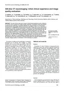
Materials and methods Treatments at DKFZ with the linac-CT scanner Siemens Primatom Since October 2002, the Siemens Primatom (Siemens OCS, Concorde, CA) has been in clinical use at the German Cancer Research Center (DKFZ) in Heidelberg, Germany. It consists of a 6 MV Siemens Primus linear accelerator and a single-slice spiral CT scanner Siemens Emotion, which are set 90 ˚ apart and share the same couch (Figure 1). Depending on the treatment room, a 180 ˚ design can also be used [6, 8]. Almost all fractionated treatments at DKFZ are carried out as IMRT. The indicated treatments are prostate cancer, head and neck cancer, paraspinal tumours, base of skull tumours, breast cancer and, more recently, pleural mesothelioma, oesophageal cancer and pancreatic cancer. Radiosurgery is used for arteriovenous malformations, lung tumours and liver metastases.
Figure 1. Treatment room with the Siemens Primatom at DKFZ Heidelberg. The linear accelerator and the CT scanner on rails share the same couch, which is rotated by 90 ˚ to switch between CT scanning and treatment position.
therefore cast is produced [9]. For intracranial radiosurgery we use either an invasive ring or the Scotch (3M, St Paul, MN) cast mask. For extracranial targets, we use either a wrap-around body cast [2] made from the same material as the head mask or a vacuum pillow [2]. Both extracranial fixation devices are complemented by a head mask to eliminate head rotations, which might translate into movements of the spine, and for single-fractionated treatment of lung and liver an additional abdominal pressure plate reduces the respiratory motion.
Treatment For all single-fractionated treatments, a control CT scan is performed directly prior to irradiation. By comparing the control CT scan to the CT scan made for treatment planning, any translational displacement is detected and the target point corrected accordingly. For fractionated treatment of intracranial targets, the repositioning accuracy of the patient’s head with the customized head mask was found to be better than 2 mm in all three dimensions [9]. We usually therefore include a 2 mm safety margin in the planning target volume (PTV), and apart from the verification of the target point on the first fraction, we do not perform further control CT scans. Fractionated treatment of extracranial targets is accompanied by frequent CT control scans during the treatment course, since even with a rigid fixation significant interfractional discrepancies are observed (see results below). The scan frequency depends on the individual case and is between once weekly for unproblematic cases, up to daily CT scans for patients with large repositioning errors and critical proximity of target structures to organs at risk.
Patient fixation Every patient at DKFZ is treated in an individually customized fixation device. For fractionated treatment of intracranial targets, a head mask made of Scotch S80
Analysis of CT scans All CT scans generated with the Siemens Primatom are performed with stereotactic localizers attached to the The British Journal of Radiology, Special Issue 2006
kV CT using a linac-CT scanner combination
fixation frame in exactly the same way as they were attached in the treatment planning CT scan. This defines a frame-based coordinate system independent of the patient’s actual position, which is a prerequisite for any further analysis. For the first fraction, lead ball bearings (BB) were additionally put onto the laser adjustment lines for target point verification, so no further portal imaging was necessary. When we started using the Siemens Primatom, the correct positioning of the patient could only be verified by manually highlighting representative anatomical landmarks on selected CT slices. For example, about three bony landmarks on the isocentre plane were predefined on the planning CT in the treatment planning system and then located on the control CT using the CT scanner console. The average coordinate difference between the scans then gave an estimation of the average displacement error. Although technically feasible, this procedure was quite time consuming and movements visible on only some CT slices could be missed. We therefore developed a new workflow to both reduce the time requirements and improve the accuracy of the analysis, and integrated it into our in-house developed radiotherapy software environment. The control CT scan is transferred via a network to our treatment planning system VIRTUOS. Inside the treatment planning system, the localizers of the control CT and the planning CT are stereotactically correlated, making the coordinates in both cubes directly comparable. The region of the control CT cube containing the target volume is then automatically matched onto the planning CT. The transformation determined in this step immediately gives the current displacement error. At the moment, we use two rigid matching algorithms: Rigid correlation matching (RCM) based on bony anatomy considers only translational movements and provides the target point correction vector, and mutual information matching (MIM) for bony and soft structures considers translational and rotational movements. Both matching algorithms derive the transformation vector T between planning volume A and transformed control volume BT by searching for maximal similarity in the region of interest V, measured by the correlation coefficient CC and the mutual information MI, respectively. The correlation coefficient between A and BT is calculated by: CC ðA,BT Þ~
X � � � � � � � � A ! x i {A � BT ! x i {BT ! x i [VA,B
ð1Þ
¯ is the mean value of A and BT the mean value whereby A of BT. A three-dimensional Fourier transformation of A and BT into the frequency space using a fast Fourier transformation (FFT) transforms the convolution in Equation (1) into a simple multiplication. After inverse transformation, we obtain the correlation volume that holds the CC values for all possible 3D translation vectors, and the global maximum can easily be found. Since we use discrete Fourier transformation, the precision is restricted to the voxel dimension. The RCM analysis of a typical CT dataset (5126512 points, 30 The British Journal of Radiology, Special Issue 2006
slices) by a standard PC takes less than 30 s. RCM matching was performed for the complete region around the target volume and separately for the upper und lower quarter. Significant differences between the three results indicate that the deviation is more complex than a pure translation. The similarity between volume A and volume BT measured by mutual information is given by: MI ðA,BT Þ~
XX a
b
pABT ða,bÞ: log
pABT ða,bÞ ð2Þ pA ðaÞ:pBT ðbÞ
where a and b are the Hounsfield units of A and B, respectively, and pA(a) the probability density of a and pAB T(a,b) the combined density of A and BT [10, 11]. We do not use all points of A and B to determine each p, but rather a sample of approximately 200 000 values, which is about 2.5% of the complete dataset. This significantly speeds up the calculation without deterioration in the result. In an iterative optimization procedure, BT is translated and rotated until MI reaches a maximum. Therefore an optimization of six variables (tx, ty, tz, and rx, ry, rz) must be performed. In our implementation, we use Powell’s approach [12] to determine the transformation where MI reaches its maximum. This approach provides subvoxel precision. The MIM analysis of a typical CT dataset (5126512 points, 30 slices) is calculated by a standard PC in about 3 min. RCM is significantly faster than MIM, always finds the global optimum and gives a transformation that can be corrected for by a simple shift of the target point. We perform RCM matching of the upper and lower quarter of the region of interest and the MIM matching only to check for deviations that cannot be corrected for by translation only. In any case, the user has to visually check that the resulting match is correct. With standard tools, such as red-green overlay and checkerboard provided by VIRTUOS, this manual check usually takes less than 1 min.
Adaptive radiotherapy In adaptive radiotherapy, deviations of patient repositioning and anatomy from the initial planning CT scan are detected and, if necessary, corrected for. This is in contrast to conventional static radiotherapy where the plan is based on one single CT scan and delivered to the patient throughout all fractions. Different levels of adaptation can be defined: In level 0, the treatment plan is based on several CT scans rather than a single one, and the information about statistical movements of the target and organs at risk are integrated into the treatment plan. This can be accomplished by defining patient-specific or at least sitespecific safety margins [13] or by including statistical methods into the inverse optimization process [14, 15]. Level 1 corrects for errors offline, i.e. the correction is done after several CT scans are gathered. Systematic interfractional errors can be detected and corrected. If the main deviation is a translation, usually it is sufficient to shift the target point and leave the plan unchanged (level 1A). If the error is more complex, the contours have to be S81
C Thieke, U Malsch, W Schlegel et al
adapted to the new geometry, and a new plan has to be generated by re-running the optimization of the inverse planning program (level 1B). Level 2 uses the same methods as level 1, but here the correction is placed in between the CT scan and the directly-following linac irradiation. By analogy with level 1 definitions, level 2A stands for shifting the target point and 2B for generating a new plan. This way not only the systematic error, but also daily random interfractional errors can be corrected. Since the patient remains in the fixation device during the adaptation procedure, the time requirements for this step are more critical than for the lower adaptation levels. Level 3 eventually also takes into account intrafractional errors. This task requires an imaging device operating during the irradiation itself and cannot be accomplished by a linac-CT scanner combination. In the following discussion we will focus on our experiences with Primatom-based radiotherapy for prostate, paraspinal and head and neck cases. However, the general aspects and conclusion apply to other indications as well.
leads to good repositioning of the prostate itself, as is indicated by the results of Beard et al [16] who reported deviations of the prostate above 1 cm in 3% of all cases after bony matching, whereas Wong et al [7] reported deviations above 1 cm in 15% of all cases without bony matching. Manually checking the soft tissues also showed that in our data the displacements of the prostate itself were bigger than the bony variations. In a separate study, the positions of the prostate, bladder and rectum were statistically analysed and taken into account by adding a margin to the gross tumour volume (GTV) and clinical target volume (CTV) to obtain the planning target volume (PTV) (adaptation level 0) [13, 17]. To reduce these margins and further improve the accuracy of prostate treatments, we are currently working on matching algorithms that will enable the automatic correction of interfractional displacements of the prostate itself on adaptation level 2. Deformation of the shape of the prostate and seminal vesicles is reported to be small relative to organ motion [18], so simply shifting the target point (level 2A) will probably be sufficient.
Paraspinal tumours
Results and discussion Dose The additional dose delivered to the patient by frequent CT scans should be as low as possible. Since we do not need the best possible image quality for localization, we use a low mAs product (which introduces some noise to the image) and only scan slices containing the target volume plus approximately 2 cm in cranial and caudal direction. This way, the measured CT dose e.g. per prostate scan was 0.003 Gy at the isocentre and 0.0053 Gy at 1 cm depth. Considering the overall benefit of higher treatment accuracy, we do not find this dose clinically relevant.
Prostate cancer Patients with prostate cancer treated at our institution are immobilized by a wrap-around body cast and a head mask. Usually they receive weekly control CT scans during the treatment course. Figure 2 shows the displacements of the bony structures around the prostate in the control scans relative to their position in the planning CT scan for 10 prostate patients (P1–P10) as they were calculated by rigid correlation matching. The symbols (m, , &) indicate the mean displacement values for each coordinate in x, y and z direction, with the range represented by the standard deviation of all values observed. Checks with RCM for the upper and lower quarter of the target volume separately showed differences below 1 mm, and checks with mutual information matching confirmed that the rotational error was negligibly small with only around 0.5 ˚ (maximum 1 ˚) for all three rotational axes. As can be seen in Figure 2, even without corrections of the target point the repositioning accuracy of the bony anatomy was very good, with displacements below 3 mm in almost all cases. The correct positioning of the bony anatomy alone already
N
S82
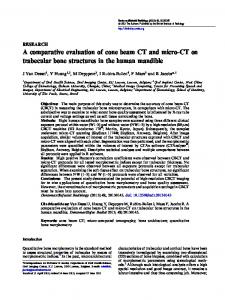
Paraspinal tumours of different histological origins are challenging because of their close proximity to the spinal cord as a critical organ at risk. For treatment we immobilize these patients by a wrap-around body cast and a head mask and perform regular control CT scans. Since the tumours are very closely related to, or even inside the bony spine, the evaluation of bony landmarks is an exact measure of the tumour position. Figure 3 shows the accuracy and precision of repositioning for seven patients with paraspinal tumours treated at our institution. Also for the paraspinal tumours, rotational errors were negligible as we verified visually, by piecewise RCM and by MIM. The overall repositioning accuracy was good. The accuracy in ventro-dorsal (y: ) direction was equal to or better than 5 mm. In lateral (x: m) and craniocaudal (z: &) direction the typical displacement was around 3 mm. However, in these directions maximal errors above 10 mm were observed. Lateral displacements especially can become critical for these patients, as it is exemplarily shown in Figure 4 for the paraspinal case P7 (a patient with a chordoma of the lumbal spine). The left panel shows the planning CT scan, the right panel shows the stereotactically matched control CT scan of fraction 20. Note the slightly lower image quality of the control CT scan due to the low mAs product we used for scanning. The contours of target, boost and spinal cord are based on the planning CT scan and, by comparing the relation of these contours to the underlying anatomy of the control scan, one immediately sees that the lateral displacement shifts the spinal cord into the high dose area intended for the boost, and that parts of the boost volume are moving out of the high dose area. Paraspinal targets are not significantly affected by intrafractional organ motion, e.g. due to breathing [19], did not show a relevant rotational component and did not change their shape during the treatment course. Therefore we could correct for setup errors by simply shifting the target point. As can be seen in Figure 3, the interfractional error had a pronounced systematic
N
The British Journal of Radiology, Special Issue 2006
kV CT using a linac-CT scanner combination
Figure 2. Interfractional setup errors in x, y, z direction of 10 prostate patients, based on bony anatomy calculated by the rigid correlation matcher. For each patient, the mean translational error and its standard deviation is plotted.
component. When several (3–4) CT scans revealed such a systematic error, we corrected the target point accordingly and performed further control CT scans (adaption level 1A). Two cases had a highly critical proximity of tumour to the spinal cord (e.g. patient 7 in Figure 4) and showed a stronger random error component, so we performed daily CT scans and corrected the target point directly prior to irradiation (level 2A).
Head and neck tumours The target volume for head and neck tumours regularly includes the base of skull and extends to the upper thoracic aperture. The patients are fixated with a head mask and a vacuum pillow. The cranial part inside the head mask is very accurately repositioned during the
whole treatment course. In contrast, the lower extracranial part shows more variations. The result is a complex deformation of the target volume that cannot be described by a translation and cannot be corrected easily by shifting the target point without changing the treatment plan. Here we show an exemplary case of a patient who was treated for teratocarcinosarcoma of the paranasal sinuses. During the treatment course frequent control CT scans were performed, and while the intracranial part was accurately positioned throughout all fractions, the lower, extracranial part of the body was systematically shifted approximately 1.5 cm along the y-axis from the middle of the treatment course onwards, see Figure 5 comparing the planning CT with the control CT of fraction 20. Note that the contours in Figure 5 refer to the planning CT and do not fit to the anatomical situation at
Figure 3. Interfractional setup errors in x, y, z direction of seven paraspinal patients, based on bony anatomy calculated by the rigid correlation matcher. For each patient, the mean translational error and its standard deviation is plotted.
The British Journal of Radiology, Special Issue 2006
S83
C Thieke, U Malsch, W Schlegel et al
Figure 4. Planning CT scan and control CT scan at fraction 20 of the paraspinal case #7. The contours of the target volume, the boost volume and the spinal cord are also shown.
fraction 20. We therefore re-drew the organ contours for fraction 20 and re-calculated the dose of the original plan on the CT of fraction 20. The results are shown in the form of dose–volume histograms (DVHs) in Figure 6. Figure 6a is the original plan based on the planning CT scan and Figure 6b is the same plan applied to the situation at fraction 20 with updated organ contours. One can see that especially the coverage of the lower target volume has significantly deteriorated. The shift of the extracranial part of the body was systematically seen on three successive control CTs, so we decided to adapt the plan to the new geometry by re-running the optimization in our inverse planning program (KonRad by Siemens OCS) for the control CT scan with the new contours, but without changing the original setting of dose constraints and weighting factors. The new plan was calculated in approximately 2 min, and as shown in Figure 6c the adapted plan resembles the original plan much better than the uncorrected one. Because the contours had to be re-drawn manually, at the moment this procedure takes too much time to fit in between the CT scan and the directly-following irradiation to correct for random interfractional setup errors. However, it allows for a very good adaptation to complex systematic variations occurring during the treatment course (adaptation level 1B).
General aspects The Siemens Primatom is a combination of a linear accelerator and a CT scanner in one room, sharing the same couch. It is built upon standard components which are clinically proven and which work reliably. The patient remains immobilized between the CT scan and the following irradiation. At the moment, we use the Primatom regularly for all patients with extracranial targets. Currently, correction of detected errors in clinical S84
practice is by target point correction either after several CT scans or for each fraction separately (level 1A and 2A) and plan re-optimization for systematic, complex setup errors (level 1B). Real time plan re-optimization (level 2B) is not practical at the moment because of the time constraints. Patients with paraspinal tumours can greatly benefit from the higher accuracy of the treatment. Target point correction seems sufficient; elastic deformation or plan re-optimization was not necessary for the patients we treated. For prostate patients, the bony anatomy is already quite precisely repositioned due to our rigid immobilization device. Here we expect further improvements by elastic matching algorithms that automatically detect the position of the prostate itself (based on Primatom CT scans) and adapt the plan either by target point correction or re-optimization. Also, for patients with head and neck tumours the quality of the radiotherapy could be significantly improved. For these cases, plan re-optimization appeared to be more important than for other tumour sites due to the complex nature of the interfractional deformations. The linac-CT scanner combination already meets all hardware requirements to completely eliminate interfractional setup errors from the treatment course. However, a fast and robust workflow is necessary for widespread use in clinical practice, and to accomplish this further development of algorithms and software tools (e.g. automatic elastic matching) is needed. Realtime plan adaptation to elastic deformations in particular is under current investigation [20] and not in clinical practice yet. Concerning the documentation of an adapted radiation treatment course, the most desirable final record would be a treatment plan where the doses to each volume element delivered throughout the course are superimposed, resulting in concise dose statistics for each structure and a single DVH for the complete The British Journal of Radiology, Special Issue 2006
kV CT using a linac-CT scanner combination
Figure 5. Exemplary head and neck case – comparison of planning CT and control CT at fraction 20. In the first row the good repositioning in the upper part of the target can be seen, and the second row shows the error of approximately 1.5 cm along the y-axis in the lower part of the target volume.
treatment. However, this requires the tracking of each voxel throughout all CT scans. Simply averaging the DVHs of the single fractions to obtain a final DVH would lead to erroneous results since, in a DVH, the spatial information is lost. Techniques for tracking the voxels are under current development; at the moment, each modified (adapted) treatment plan is documented separately (as in Figure 6a,c). Our patient immobilization device with customized wrap-around body casts alone leads to quite high repositioning accuracy, but is also quite labour and time intensive to build. When using adaptive radiotherapy
strategies, the fixation can probably be made less sophisticated, lowering the overall workload and further strengthening the role of a combined imaging/treatment device such as the linac-CT scanner combination.
Conclusions The linac-CT scanner combination is a device for adaptive radiotherapy that delivers all information necessary to eliminate interfractional setup errors from a fractionated treatment course. Currently available matching algorithms
Figure 6. Same case as in Figure 5. Dose–volume histograms of (a) original plan, applied to planning CT, (b) original plan, applied to fraction 20 with updated contours and (c) re-optimized plan. For better comparison, the 80% dose/90% volume point is highlighted. The structures are 1-upper target volume, 2-lower target volume, 3-left parotid gland, 4-spinal cord, 5-right parotid gland.
The British Journal of Radiology, Special Issue 2006
S85
C Thieke, U Malsch, W Schlegel et al
and software components make it well suited for real-time and off-line target point corrections, and for off-line reoptimization. Further investigation needs to be carried out until it can be used clinically for real-time re-optimization. In principle the device is not suited for adaptation to intrafractional variations.
References 1. Lohr F, et al. Noninvasive patient fixation for extracranial stereotactic radiotherapy. Int J Radiat Oncol Biol Phys 1999;45:521–7. 2. Herfarth KK, et al. Extracranial stereotactic radiation therapy: set-up accuracy of patients treated for liver metastases. Int J Radiat Oncol Biol Phys 2000;46:329–35. 3. Groh BA, Siewerdsen JH, Drake DG, Wong JW, Jaffray DA. A performance comparison of flat-panel imager-based MV and kV cone-beam CT. Med Phys 2002;29:967–75. 4. Jaffray DA, Siewerdsen JH, Wong JW, Martinez AA. Flatpanel cone-beam computed tomography for image-guided radiation therapy. Int J Radiat Oncol Biol Phys 2002;53:1337–49. 5. Uematsu M, et al. A dual computed tomography linear accelerator unit for stereotactic radiation therapy: a new approach without cranially fixated stereotactic frames. Int J Radiat Oncol Biol Phys 1996;35:587–92. 6. Kuriyama K, et al. A new irradiation unit constructed of self-moving gantry-CT and linac. Int J Radiat Oncol Biol Phys 2003;55:428–35. 7. Wong JR, et al. Image-guided radiotherapy for prostate cancer by CT-linear accelerator combination: prostate movements and dosimetric considerations. Int J Radiat Oncol Biol Phys 2005;61:561–9. 8. Cheng CW, et al. Commissioning and clinical implementation of a sliding gantry CT scanner installed in an existing treatment room and early clinical experience for precise tumor localization. Am J Clin Oncol 2003;26:e28–e36. 9. Karger CP, Jakel O, Debus J, Kuhn S, Hartmann GH. Threedimensional accuracy and interfractional reproducibility of
S86
10.
11. 12. 13.
14.
15.
16.
17.
18.
19.
20.
patient fixation and positioning using a stereotactic head mask system. Int J Radiat Oncol Biol Phys 2001;49:1493–504. Collignon A, et al. Automated multi-modality image registration based on information theory. Information Processing in Medical Imaging 1995;262–74. Viola P, Wells W, III. Alignment by maximization of mutual information. Int J Computer Vision 1997;137–54. Press WH, Teukolsky SA, Vetterling WT, Flannery BP. Numerical recipes in C. Cambridge University Press, 1995. Didinger B, Schulz-Ertner D, Wannenmacher M, Debus J. [Modern techniques in the radiotherapy of prostate cancer. Non-surgical treatment options for localized stages]. Radiologe 2003;43:448–54. Unkelbach J, Oelfke U. Incorporating organ movements in inverse planning: assessing dose uncertainties by Bayesian inference. Phys Med Biol 2005;50:121–39. Birkner M, Yan D, Alber M, Liang J, Nusslin F. Adapting inverse planning to patient and organ geometrical variation: algorithm and implementation. Med Phys 2003;30:2822–31. Beard CJ, et al. Analysis of prostate and seminal vesicle motion: implications for treatment planning. Int J Radiat Oncol Biol Phys 1996;34:451–8. Didinger B. Beru¨cksichtigung von interfraktionellen Bewegungen bei der Pra¨zisionsbestrahlung des Prostatakarzinoms - Konsequenzen fu¨r Zielvolumina und Dosis-Volumen-Histogramm. 2003. M.D. Thesis, University of Heidelberg, Germany. Deurloo KE, et al. Quantification of shape variation of prostate and seminal vesicles during external beam radiotherapy. Int J Radiat Oncol Biol Phys 2005;61:228–38. Shiu AS, et al. Near simultaneous computed tomography image-guided stereotactic spinal radiotherapy: an emerging paradigm for achieving true stereotaxy. Int J Radiat Oncol Biol Phys 2003;57:605–13. Mohan R, et al. Use of deformed intensity distributions for on-line modification of image-guided IMRT to account for interfractional anatomic changes. Int J Radiat Oncol Biol Phys 2005;61:1258–66.
The British Journal of Radiology, Special Issue 2006