Jul 29, 2013 ... Clausiusstrasse 59. 8092 Zurich, Switzerland
.
ABSTRACT. Visible Light Communication (VLC) with Light Emitting.
LED-to-LED Visible Light Communication Networks Stefan Schmid
Giorgio Corbellini
Disney Research & ETH Zurich Stampfenbachstrasse 48 8006 Zurich, Switzerland
Disney Research Zurich Stampfenbachstrasse 48 8006 Zurich, Switzerland
[email protected] Stefan Mangold
[email protected] Thomas R. Gross
Disney Research Zurich Stampfenbachstrasse 48 8006 Zurich, Switzerland
ETH Zurich Clausiusstrasse 59 8092 Zurich, Switzerland
[email protected]
[email protected]
ABSTRACT Visible Light Communication (VLC) with Light Emitting Diodes (LEDs) as transmitters and receivers enables low bitrate wireless adhoc networking. LED-to-LED VLC adhoc networks with VLC devices communicating with each other over free-space optical links typically achieve a throughput of less than a megabit per second at distances of no more than a few meters. LED-to-LED VLC adhoc networks are useful for combining a smart illumination with low-cost networking. We present and evaluate a software-based VLC physical layer and a VLC medium access control layer that retain the simplicity of the LED-to-LED approach. The design satisfies the requirement that LEDs should always be perceived as on with constant brightness. In each VLC device, in addition to an LED, only a low-cost microcontroller is required for handling the software-based communication protocol. The results of our performance measurements confirm recent claims about the potential of LED-to-LED VLC adhoc networks as a useful technology for sensor networks, smart and connected consumer devices, and the Internet-ofThings.
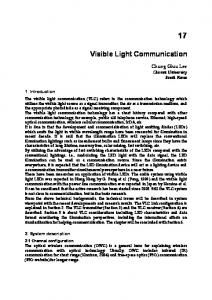
c Disney). LED-to-LED Figure 1: Concept art ( VLC adhoc network with PHY and MAC layers that use LEDs as transmitter and receiver.
1.
INTRODUCTION
Visible Light Communication (VLC) with Light Emitting Diodes (LEDs) as transmitters and receivers provide a novel approach to enable low bitrate wireless adhoc networking for short distances [17]. LED-to-LED VLC networks are formed by VLC devices that communicate with each other over freespace optical line-of-sight channels and typically achieve an overall network throughput of less than a megabit per second at distances of no more than a few meters. Low-complexity LED-to-LED VLC adhoc networks are useful when deploying sensor networks, home networks, smart illumination, or when connecting consumer devices like smart toys. These scenarios are characterized by frequent additions and removals of endpoints (the neighbor’s kid may bring over a smart toy) and cost sensitivity. Such networks can exploit the ubiquitous presence of LEDs and leverage their ability to act as cost-effective transceivers (transmitters and receivers) – while allowing the LEDs to continue to operate as a lighting device. In such low-complexity VLC networks, devices are not configured to operate with photodetectors to receive data; instead the LEDs can be used for data reception [6, 7, 18, 5]. The VLC devices use off-the-shelf 8-bit microcontrollers, powerful enough to operate the required adhoc communication protocols, to coordinate the network and medium ac-
Categories and Subject Descriptors C.2 [Computer-Communication Networks]: Network Architecture and Design—Wireless Communications
Keywords Visible Light Communication, MAC Protocol, Free-Space Optics
Permission to make digital or hard copies of all or part of this work for personal or classroom use is granted without fee provided that copies are not made or distributed for profit or commercial advantage and that copies bear this notice and the full citation on the first page. Copyrights for components of this work owned by others than the author(s) must be honored. Abstracting with credit is permitted. To copy otherwise, or republish, to post on servers or to redistribute to lists, requires prior specific permission and/or a fee. Request permissions from
[email protected]. MobiHoc’13, July 29–August 1, 2013, Bangalore, India. Copyright is held by the owner/author(s). Publication rights licensed to ACM. ACM 978-1-4503-2193-8/13/07 ...$15.00.
1
out of sync
Table 1: Terms and abbreviations. Term ACK ADC CA CCDF CRC CSMA CW CW Slot FCS IDLE MAC MPDU OFF ON PDU PHY PPM QoS RX SAP SFD T THRS TX
... ...
Description Acknowledgement PDU Analog-to-Digital Converter Collision Avoidance Complementary Cumulative Distrib. Fct. Cyclic Redundancy Check Carrier Sense Multiple Access Contention Window with 16 CW slots Slot used for CA (duration: 16 T) Frame Check Sequence used by CRC Idle mode (no TX, no RX) Medium Access Control MAC PDU Symbol OFF: slot energy < THRS Symbol ON: slot energy > THRS Protocol Data Unit Physical Pulse Position Modulation Quality-of-Service Reception mode (no IDLE, no RX) Service Access Point Start Frame Delimiter Target slot duration, 500 µs Detection threshold, 10bit ADC reference Transmission mode (no IDLE, no RX)
device 1 500µs! ON
OFF bit 0
... ... time
periodic idle pattern OFF ON bit 1
ON
OFF bit 0
OFF ON bit 1
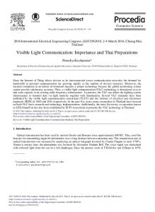
(a) Periodic idle pattern: ON-OFF-OFF-ON (bit 0 1).
(b) Measurement of two synchronized idle patterns. Figure 2: Idle pattern transmitted by VLC devices during IDLE mode: LEDs are periodically switched on and off and emit light repeatedly. VLC devices in range of each other synchronize automatically.
cess. The LED-to-LED network obscures the exchange of messages in the existing illumination. The exchange of visible light messages has no effect on the level of brightness (so that an LED appears to be switched on all the time). The paper describes a novel design of a complete and lowcomplexity VLC Physical (PHY) layer and a contentionbased VLC Medium Access Control (MAC) protocol layer and evaluates the effectiveness of these layers. The novel nature of this kind of adhoc network requires that we present some aspects of the PHY layer. We introduce a time synchronization to improve link reliability. The efficiency of the synchronization protocol is critical for the link throughput especially when the distance between the different devices increases. We also define a method to adapt the sensitivity of the VLC receiver: A threshold adaptation enables VLC devices to operate reliably even when the level of ambient light changes. The adaptation uses the preamble that also serves as start indicator at the beginning of each frame. For the MAC layer, a Carrier Sense Multiple Access with Collision Avoidance (CSMA/CA) protocol is defined and its performance evaluated. The MAC protocol relies on a distributed CSMA approach without priority support, i.e., no guarantee of Quality-of-Service (QoS). There is no centralized, contention-free period available for any controlled medium access. Table 1 summarizes the abbreviations used in this paper. The PHY layer, with its novel synchronization method and adaptive frame reception, and the MAC layer, with its distributed CSMA medium access protocol, are described in Sections 2 and 3, respectively. The system’s performance is evaluated in Section 4. Section 5 provides a brief summary of related work and is followed by the conclusions in Section 6.
2.
in sync
device 2
PHY-Protocol Data Units (PHY-PDUs), which are referred to as frames when they are transmitted over the medium. The VLC system consists of small consumer devices (here referred to as VLC devices) that are equipped with one or more LEDs for light effects and communication. A microcontroller is used to process the transmitted and received signals (PHY layer) and to run the medium access control protocols (MAC layer). In the setup described, VLC devices use the same LEDs for transmission and reception. In case of multiple LEDs embedded in the same VLC device, they can be used in a time multiplexed way [17]. The communication is organized using time slots of target duration T=500 µs. With the given system design, the VLC system could reach a higher data throughput with shorter slot durations. However, we selected this value to ensure that a common low-cost 8-bit microcontroller has sufficient time for processing. Slots in which at least one VLC device emits light are interpreted to carry the symbol “ON”. Slots during which no VLC device emits any light are interpreted as carrying the symbol “OFF”. Depending on device locations, ambient light, and network conditions, different VLC devices might interpret the same slot differently at the same time, i.e., as ON or OFF.
2.1
IDLE, TX, and RX Modes
Each VLC device operates in one of three communication modes and changes its mode when required by the communication protocol. A VLC device remains in IDLE mode if it does not have any frame to transmit and if it is not receiving any frame. While in IDLE mode, a VLC device periodically transmits the so-called idle pattern to let the LED appear to be switched on at constant brightness, as shown in Figure 2. The device transmits ON and OFF symbols following a predefined pattern with a given alternation frequency (1/(2 ∗ T )) where T is the duration of each slot (T =500 µs), so that the light is perceived with constant intensity. The periodic ON-OFF idle pattern during IDLE
SOFTWARE-DEFINED PHY-LAYER
The PHY layer is responsible for the frame delivery over the free-space optical medium, for synchronization, and for the medium idle/busy sensing. The PHY layer operates with
2
Table 2: Bit encoding with 2-PPM. bit 0 1
first symbol ON OFF
second symbol OFF ON
remark: ON = light is emitted; OFF = no light
mode consists of the periodic repetition of four consecutive time slots {ON-OFF-OFF-ON} (see Figure 2(a)), which can be interpreted as a periodic repetition of bit 0 and bit 1. A VLC device operates in TX mode when it transmits a frame and in RX mode during the reception of a frame. In TX mode, the device modulates the slots with the 16slot preamble and the subsequent bitstream, and as a result the ON and OFF symbol pattern changes depending on the transmitted frames (the data bitstream). The bit encoding is a 2-Pulse Position Modulation (2-PPM) with 50% duty cycling and is indicated in Table 2. Because 2-PPM coding is applied, on average, the same number of ON symbols and OFF symbols are emitted. As a consequence, there is no visual flickering even when bit streams would be correlated with, for example, long streams of only bit 0. Also during the IDLE mode, the LEDs continue to appear switched on without flickering. On the receiver side, in RX mode, a VLC device still transmits ON and OFF symbols as in IDLE mode (a continuation of the IDLE pattern), but it interprets the amount of incoming light during each OFF symbol as incoming symbols, because it intends to receive a frame.
2.2
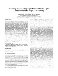
Figure 3: Measurement of incoming light during slots at which the device itself does not emit light. Top: transmitted pattern. Bottom: discharging voltage at the receiving LED.
cannot do both at the same time. To use single LEDs as transceivers, the VLC device needs to alternate transmission and reception periods. And half of the slots are not used for reception, because they are used to periodically emit light, to let the LED appear to be switched on.
2.3
Synchronization
Devices that use a slotted VLC scheme to communicate need to operate in a time-synchronized way: VLC devices in range of each other are synchronized if the beginning of each slot occurs at the same time for all devices. Synchronization errors such as clock shift and jitter are undesirable and reduce the system performance [2]. Using an LED in reverse bias acting as a receiver leads to low sensitivity to optical energy (in comparison with photodetectors). This setup makes obtaining an accurate synchronization more difficult. A possible solution is to leave devices un-synchronized and transmit a dedicated synchronization preamble before each frame [17, 9]. If a portion of time is dedicated to the transmission of the preamble for synchronisation, the overhead increases. In our solution, we achieve synchronization of VLC devices that are in range with each other differently, without the need of transmitting a dedicated synchronization preamble: The periodically repeated idle pattern is continuously used to synchronize the VLC devices. This limits the protocol overhead as no dedicated preamble is required. To obtain synchronization, all devices follow the same idle pattern ({ON-OFF-OFF-ON}, as indicated in Figure 2) so that all LEDs are perceived as switched on. VLC devices remain in IDLE mode as long as they do not have data to transmit or receive. When powered on, a VLC device performs an initial measurement that typically lasts for a few milliseconds: The device measures the current (ambient) light intensity over several measurement slots. After the initial measurement, every VLC device continuously measures the amount of light detected in measurement slots and compares the values of two consecutive measurements. If the amount of light measured during two consecutive slots is close to each other and if it is also similar to the ambient light measured earlier, the device can conclude that either there is no other device in its vicinity, or that it is synchronized to the other devices near by (within communication range). However, if the device detects that the two consecutive measurement values deviate (with some hysteresis), this might mean that there is another light-emitting device in the vicinity. In this case, for example, if a first VLC device detects that the incoming light in slot n is larger than slot n+1, this means that it is sampling too early and its
Receiving with an LED
Often, VLC systems use LEDs for transmission and photodetectors for reception. A photodetector efficiently converts light photons into electrical current. Already with one LED and one photodetector, it is possible to build a oneway VLC system in which frames are transmitted from the LED to the photodetector, but this kind of VLC system does not provide a feedback channel back to the LED. To build a two-way VLC system that allows feedback, two components per device would be required: an LED to transmit, and a photodetector to receive. It is possible to use the LED as photodetector to receive optical messages using the same LED that is used for transmission [6], a set up that reduces the complexity per device. This approach is taken here. Figure 3 illustrates how LEDs that are charged in reverse bias can be used to receive incoming light. As can be seen in the figure, depending on the intensity of the incoming light, the LED capacitance discharges at different speed. The stronger the incoming light, the faster the discharge. With an adaptive threshold parameter (THRS), the two different symbols ON and OFF can be determined and differentiated by the receiving VLC device at the end of each slot used for measurements. A drawback of using the LED as a receiver is the fact that an LED is less sensitive than a photodetector; this property negatively affects the achievable communication range. A second drawback is the resulting limited throughput due to the required multiplexing: Whereas with two components per VLC device, transmission and reception can occur at the same time in parallel, with a single LED per VLC device, this LED can either only transmit or only receive but
3
ambient & VLC light
ambient light
THRS [0…1023]
devices synced & in IDLE mode
no change during frame reception
source in TX mode
destination in RX mode
...
... … idle patterns
frame ... 16 slot SFD preamble (bit pattern: 00110011)
SFD preamble detection
...
end of reception
time
ON OFF ON OFF OFF ON OFF ON ON OFF ON OFF OFF ON OFF ON
...
(a) Start Frame Delimiter (SFD)
time
Figure 4: THRS adaption before and after frame reception, logged at microcontroller.
local clock must be shifted forward, that is, it must sample later. On the other side, at the second VLC device, this means that the incoming light in slot n is smaller than slot n+1. Therefore the second VLC device will need to shift its clock backward, i.e., it needs to advance the sampling. By applying a small shift (repeatedly if needed), VLC devices synchronize their time slots during IDLE mode, without the explicit use of a synchronization preamble. This method is not limited to the synchronization of only a pair of devices, it also works with a larger number of devices that are in range of each other. Speed and accuracy of the synchronization can be increased by separating the measurement for synchronization from the two measurement slots that are used for symbol reception (two consecutive symbols form one bit). Such a separation would introduce two extra measurement slots of short duration: One before and one after the two original measurement slots. This setup allows stable synchronization even in TX and RX mode, because dedicated time is allocated to synchronization during all modes of operation.
2.4
(b) SFD measurement Figure 5: The SFD preamble: DATA and ACK frames start with the SFD, to achieve reliable frame detection. In addition, the SFD serves as preamble so that each receiver updates its detection threshold (THRS) if needed.
same idle pattern. With ambient light, THRS remains at its minimum level. This changes as soon as the Start Frame Delimiter (SFD) is detected, as described in Section 2.5.
2.5
Start Frame Delimiter (SFD) Preamble
To set THRS at each VLC device to the optimal values, receivers should receive patterns consisting of an even number of symbols ON and OFF. Therefore, each time a VLC device needs to transmit a frame, it precedes the transmission by a so-called SFD preamble (sixteen slots), which is used to alert the receiver that a frame will follow. The SFD preamble is chosen so that the receiver can increase the detection threshold up to the correct value. At the end of the SFD, at any receiving VLC device, the value of THRS is adapted to the current ambient light situation and closer to the optimal (but unknown) value for THRS so that the receiver is able to reliably receive the subsequent frame. As soon as the SFD is decoded, the receiver stops updating THRS and keeps it constant until the end of the current frame reception. After the end of the reception, THRS adapts again and converges to the value related to the ambient light. In case the level of ambient light did not change during the frame exchange, this is a value similar to THRS before the frame exchange. Figure 4 illustrates this adaptive process.
Adaptive Bit Detection Threshold (THRS)
Light intensity modulation is used to differentiate and detect symbols ON and OFF. At the receiver side, the ability of detecting and differentiating symbols ON or OFF is affected by the attenuation of the transmitted light from the source VLC device and the intensity of the ambient light. Assuming that transmitters and receivers are synchronized, an ideal detection threshold is helpful to reliably decode the received bits by distinguishing the ON and OFF symbols. Such a threshold is difficult to determine because the level of ambient light changes over time. An optimal detection threshold is the average of the amount of light corresponding to the reception of a symbol ON and the amount of light corresponding to reception of a symbol OFF (see Figure 4). Consider two devices that are out of communication range of each other. At the end of the first period of the synchronization, the adaptive bit detection thresholds THRS at both devices are set to the average level of the ambient light, independently. Then, each device continuously updates its THRS value averaging the amount of light detected during slots that were used for measuring incoming light (using a sliding window). Since they are out of range, the two devices remain un-synchronized and stay in IDLE mode as long as there is no data to transmit. When the two devices are placed close to each other with the LEDs pointing towards each other’s field of view, they try to synchronize. After the VLC devices achieve synchronization, the devices emit and receive light at the same time: They follow the
2.6
Carrier Sensing
A VLC device interprets the medium as busy or idle depending on ongoing frame transmissions and/or the level of incoming ambient light. If the MAC layer requests a carrier sensing with the PhySense_req() service primitive via the PHY-Service Access Point (PHY-SAP) to the PHY layer, the PHY reports back the information about whether the optical channel is busy or clear. The PHY layer reports that the channel is clear if the current value of THRS is comparable to the instantaneous level of ambient light. In our testbed, THRS is always updated using the measured light of the last 16 slots. Therefore, if during these last slots
4
Header
application
MAC-PDU:
MAC-SAP MacDataDeliver(*_req,*_cnf, *_ind,*_res)
Frame Body: payload
5
FCS
0...255
2
Frame Body: MAC-PDU
VLC-MAC
PHY-PDU: 7…262 SFD (16 slot) tx time: 64 ms…2104 ms
PHY-SAP PhyPduDeliver(*_req,*_cnf,*_ind) PhySense(*_req,*_cnf)
numbers indicate size [Byte]
VLC-PHY
Figure 7: MAC- and PHY-PDU definition. medium
an initial first wait time of 16 slots is followed by the CW of 16 SFD preamble durations, before the start of a frame exchange. The initial waiting time is needed to ensure that ACK frames are not interfered with. There is a short idle time of four slots between a DATA and ACK frame which must not be misinterpreted as idle channel. Within the CW, there is a maximum of 16 CW slots; each CW slot has the duration of 16 T=16×500 µs (i.e., the SFD preamble duration). A VLC device that intends to transmit a DATA frame selects one of the sixteen possible CW slots for its transmission: Each CW slot is assigned the same probability of 1/16 to be selected for the transmission start (uniform distribution). This random selection ensures a minimal collision probability. However, before this target CW slot is reached, the VLC device senses the optical medium for each of the preceding CW slots. The device starts transmitting the DATA frame at the target slot only if the medium did not get used by any other VLC device at one of the earlier CW slots. When the medium is detected as busy at such an earlier CW slot (another VLC device has selected an earlier CW slot for its own medium access), the VLC device stops the contention process and switches to RX mode. Then, upon detecting the medium to be idle for the duration of one CW slot (16×500 µs), the device starts again sensing the medium for each following CW slot to eventually start transmitting the DATA frame when the selected target CW slot has been reached. In unicast, with one unique VLC device as destination, DATA frames that are completely received are acknowledged immediately with an ACK frame from the destination back to the source VLC device. The ACK is transmitted back to the source device right after the successfully received DATA frame, after a short waiting time of four slots, as indicated in Figure 8(b). The waiting time is needed for the system to remain synchronized. Each message begins and ends during the second ON slot of the idle pattern. When a device receives a message,
Figure 6: Reference model of the VLC system. all VLC devices are in IDLE mode, the deviation between the values observed is small; otherwise a large deviation is detected. If the deviation is higher than the difference between THRS and the instantaneous level of ambient light, the PHY layer reports that the channel is busy. This situation is reported with the PhySense_cnf(ON/OFF) service primitive at the PHY-SAP. This information is then used by the MAC protocol to coordinate the medium access, as described in detail in Section 3. Figure 6 illustrates how the layer entities communicate via SAPs and service primitives.
3.
LOW-COMPLEXITY MAC-LAYER
A reference model for communication networks defines layers, functions, services, SAPs, and service primitives exchanged by the layer entities via these SAPs. A layer entity can be interpreted as a service provider that serves the higher layer entity. The VLC system reference model is shown in Figure 6. This model is an abstraction of the real implementation. The figure illustrates how MAC and PHY interact via the PHY-SAP with so-called service primitives that are abstractions of discrete, instantaneous events (*_req for requests, *_cnf for confirmations, *_ind for indications, and *_res for responses). A MAC layer entity serves the application layer by providing the data delivery service, which is requested via the MacDataDeliver_req(data) primitive at the MAC-SAP. The MAC layer relies on PHY services at the PHY-SAP, with primitives like, for example, the PhyPduDeliver_req(MAC-PDU) primitive. Two types of frames are used: DATA and Acknowledgement (ACK). The DATA frame body contains the application payload of variable size (0. . . 255 Byte). The ACK frames are control frames used to acknowledge a successful MAC-PDU reception and are transmitted by the destination device back to the source device, right after the DATA frame (after a short transceiver turnaround time of four slots). The structure of the two frames is given by the Protocol Data Unit (PDUs) illustrated in Figure 7 and defined in Table 3. The bit pattern of a frame is determined by the PHY-PDU, which encapsulates a MAC-PDU (MPDU). Each MAC-PDU is composed of various elements that are used to manage communication and error handling. The MAC-PDU of a DATA frame contains the payload of the application. The MAC-PDU of an ACK frame is of a similar structure, but without payload. A Carrier Sense Multiple Access with Collision Avoidance (CSMA/CA) protocol is used to coordinate how VLC devices access the optical medium. Figure 8(a) shows an example of a DATA/ACK frame exchange with the preceding Contention Window (CW). After the medium became idle,
Table 3: DATA & ACK Frame Structure 1. 2.
3. 4.
5
Element SFD Header: 2.1 frame body size 2.2 frame control 2.3 destination address 2.4 source address 2.5 sequence number Frame Body: - for DATA - for ACK FCS
Byte (Slots) 1 (16)
Time [ms] 8.0
1 1 1 1 1
8.0 8.0 8.0 8.0 8.0
(16) (16) (16) (16) (16)
0 - 255 (0 - 4080) 0 (0) 2 (32)
0.0 - 2040.0 0.0 16.0
1 x CW slot initial wait
16 x CW slot in Contention Window (CW)
… busy
at MAC, and anything related to advanced security is handled by higher layers if feasible. VLC devices authenticate against each other and synchronize as soon as they are in communication range of each other. There is no need for a protocol that manages association and authentication, as long as devices can be identified without ambiguity. In our testbed, the address range is relatively small (1 Byte), which allows to realize a small number of unique device addresses.
4 slots
DATA
ACK
random start
time
size of CW slot = 16 slots
(a) Collision avoidance and DATA / ACK 1 x CW slot initial wait
ACK timeout & retry
16 x CW slot
… busy
4.
random start
collision or CRC error
4.1
time
Figure 8: Contention-based medium access.
DATA
DATA
ACK
receiver
Testbed
The testbed consists of Atmel ATmega328P evaluation boards [3] connected to a computer. The computer generates the traffic for all boards and collects the measurement results. Each evaluation board operates one transceiver LED to mimic one VLC device. All VLC devices operate the PHY and MAC software on their microcontrollers without relying on the connection to the computer. Unless stated otherwise, payload is generated so that the VLC devices operate in saturation. This setup is the interesting point of operation that we look at when evaluating the contention-based access protocol. In saturation, all VLC devices have always at least one packet to transmit. Therefore, the distribution of the inter-arrival time is not relevant. Payload of random content (uncorrelated random bit pattern) with different sizes is generated. The LEDs are located so that they can all communicate with each other: there are no hidden VLC stations, as indicated in Figure 10. In all evaluation steps, the same type of LED is used: a 5 mm red LED, type Kingbrigth L-7113SEC-J3, with transparent case. This LED has a peak wavelength of 640 nm, a 20◦ field of view (radiation angle), and a brightness of 12000 mcd. This type was selected because it is common and widely available. Each board connects an LED to the microcontroller. We are interested in counting successful frame transmissions and measuring the time it takes to deliver them (including waiting time and retransmission time, if any). The tests were performed in an office indoor space with windows but no direct sunlight, during the day, and with normal office artificial lighting.
(b) Timeout and retry after missing ACK
transmitter
EVALUATION
DATA
40ms
Figure 9: DATA/ACK frame exchange.
it computes the final CRC and transmits the ACK starting at the second following ON slot. With the CSMA/CA approach, multiple VLC devices might select the same CW slot and hence a so-called collision might occur. Collisions are not directly detected by the transmitting devices. Instead, ACK timeouts indicate a missing ACK frame and lead to retransmission. As indicated in Figure 8(b), in case the ACK is not received within the timeout interval, a retransmission can be initiated. A timeout interval of 134 slots is applied. This interval helps to maintain a synchronized contention avoidance protocol behavior when some devices detect and receive the ACK, but other devices miss the SFD preamble of the ACK frame and therefore time out. When retransmitting a previously failed DATA frame, a new collision avoidance process with the same CW size as before follows. After a number of transmission attempts (four in our testbed, the initial attempt followed by three retransmissions), the DATA frame is discarded and in case there is another MPDU waiting, this next MPDU is processed. In addition to unicast, broadcast transmission is possible. No ACK is transmitted by the receiving VLC devices back to the broadcasting device upon successful reception of the broadcast frame. The address 255 is used to identify a broadcast frame. Figure 9 shows a measured DATA / ACK frame exchange. Devices remain synchronized during the frame exchange. Hence, the receiving device (while in mode RX) can transmit compensating ON symbols periodically to appear on at the same brightness as it was during mode IDLE before. During DATA and during ACK transmission (while in mode TX) the 2-PPM bit encoding (two slots per bit) maintains this constant brightness and mitigates visible flickering at the transmitter. LED-to-LED VLC networking might be used in consumer electronics of low complexity with limited need for data security (for example, connected toys). Data is not encrypted
4.2
Single Link
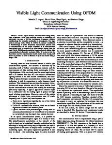
Figure 11 shows the achievable maximum throughput, i.e., the saturation throughput, in a scenario in which one VLC
Figure 10: Testbed with boards and LEDs.
6
link saturation throughput [b/s]
900
transmit a frame. The minimum is the transmission time over the medium, which can be taken from the curves at probability 1, at the top of the graph. The prolonged delays result from additional waiting and retransmission times. At closer distance (30 cm), retransmissions do not occur and the CCDFs of the three payload sizes show similar behaviors (solid lines). At the larger distance (230 cm), the CCDFs indicate a considerable increase of delivery delay (dashed lines). This behavior is due to the high number of retransmissions that occur because of the many CRCs failing at such a long distance. According to the figure, around 60 % of the frame transmissions are unsuccessful and require at least one retransmission. When retransmissions occur, the resulting delivery delay increases towards delays that might be unacceptable: In particular, very long delivery delays can be seen in the case of the long payload, 100 Byte. Keeping this in mind, since such delays might be undesirable, VLC should be applied when either a smaller number of retransmissions is allowed before discarding a packet, or the payload sizes are small. For example, in a VLC application for geolocation and indoor tracking, broadcasting IPv6 addresses from LED light bulbs requires only a payload size of less than 20 Byte.
800 700 600 100 Byte 50 Byte 1 Byte
500 400 300 200 100 0 0
0.5
1
1.5 distance [m]
2
2.5
3
Figure 11: Throughput over distance for a single link. The system operates reliably at distances of up to 2 m. 1
P(Delay>x)
0.8 0.7 0.6 0.5
1 Byte
50 Byte
100 Byte
30cm 230cm
4.3
0.4 0.3 0.2
0.1 0
500
1000
1500 2000 2500 x [milliseconds]
3000
3500
Network
The achievable system saturation throughput in the scenario of networked devices is indicated in Figure 13. Multiple VLC devices that are all in communication range of each other are active (up to six transmitters). Figure 10 shows the testbed setup used for this measurement. Because of the CSMA/CA protocol applied here, the throughput decreases with increasing number of contending VLC devices. This is expected, because colliding frames can occur in contentionbased protocols. Collisions consume time, and this waste of time is undesirable. In addition, collided frames lead to retransmissions, which consume additional resources. Because of the large expected increase of the delay due to retransmissions, higher collision probabilities should be avoided. However, because of the limited field of view of the used LEDs, we can assume that only a small number of VLC devices, say, two to three VLC devices, will be in communication range of each other and will compete for medium access. This is the reason why we focus on setups with a moderate number of networked VLC devices. In the figure, the case of one transmitter is comparable to the single link scenario that was discussed earlier.
4000
Figure 12: Data transmission delays, including waiting, contention, retransmission times. Single link with different payload sizes.
device continuously attempts to transmit to another VLC device. Except the single transmitter and single receiver, there is no other VLC device in the system. The two LEDs are pointed to each other, and the distance between them is varied between 10 cm and 250 cm. Throughput results for different payload sizes are shown. At distances larger than 2.3 m, the achievable link saturation throughput drops with the increasing distance, down to zero at around 2.5 m. Because of the CSMA/CA protocol applied, the saturation throughput depends considerably on the payload size: With a small payload size of 1 Byte, the saturation throughput is much smaller than with 100 Byte (around 40 b/s instead of 800 b/s). CSMA/CA is not needed when only one transmitter is active. However, the configuration is kept as defined in Section 3, to be able to compare the results to the network scenarios (below and Figure 13). Figure 12 illustrates the Complementary Cumulative Distribution Function (CCDF) for the delivery delay, for three different payload sizes. For all payload sizes, distributions for two distances (30 cm and 230 cm) are shown. The delivery delay is the time between (1) the packet generation event with the arrival at the transmitting VLC device, and (2) the event when the receiver received the associated data frame successfully. The figure illustrates the time that it takes to
4.4
Power Consumption
Table 4 shows the average power consumption for different device modes. The first row indicates the power consumption of the evaluation board and the microcontroller running an empty program without attached LEDs. During each slot of duration T, each VLC device processes the signal that has been received in the preceding slot. The processing cost changes from slot to slot and depends on the current mode (idle, receiving, transmitting) of the device. Slot duration is long enough to guarantee that when a device begins a new slot it is not processing any signal. After the end of the processing, the microcontroller is put to sleep mode to save energy until the start of the new slot. The power consumption for the three device modes are only slightly different. The difference of around 1 mW is due to increased processing cost when receiving and transmitting a packet.
7
power [mW] [mW] [mW] power [mW]power [mW]power [mW][mW] power [mW]power power [mW]power power
system saturation throughput [b/s]
900 payload: 1 byte per frame payload: 10 byte per frame payload: 20 byte per frame
800 700 600 500 400 300 200 100 0
1
2
3 4 5 # transmitting VLC devices
6
Figure 13: System saturation throughput in the network scenario. CSMA/CA causes throughput to decrease with increasing number of contending VLC devices.
power consumption [mW] 221.134 288.136 288.601 289.020
0
10 time [ms] 5 (a) IDLE10 mode time [ms] 5 10 time [ms] 5
5
5 5
5
5
10 time [ms] 10 time [ms] 10 (b) RX mode time [ms] 10 time [ms] 10 time [ms] 10 time [ms]
15
20
15
20
15
20
15
20
15
20
15
20
15
20
15
20
15
20
Figure 14: Power consumption over time for the three different device modes.
light is realized by modifying PPM pulse durations. The standard defines user data communication as well as management functions such as authentication, encryption, and the distribution of data across the 802 architecture. The approach described here follows a different direction; our approach aims towards highest simplicity and the re-use of existing hardware components embedded in the VLC devices. The simplicity of this design is reflected by the fact that we rely on LEDs and microcontrollers instead of dedicated communication systems. Security other than simplest device identity handling is not addressed. This approach can be referred to as steganographic networking [11]: The LEDto-LED VLC network obscures the exchange of messages in the visible light. The objective is to hide the communication into already existing illumination. The idea to use LEDs as receivers is described by Dietz et al [6, 7]. Applications scenarios have been demonstrated at conferences [18, 5]. This paper goes further and introduces and evaluates MAC protocol, synchronization, and system aspects such as communication range, performance, and device power consumption. Research challenges in the domain of VLC are summarized in [14, 8, 12]. One challenge is to increase the communication throughput. Increasing the throughput by what is referred to as Multiple-Input-Multiple-Output (MIMO) transceivers is discussed by Azhar et al. and O’Brien et al. [4, 15]. The approach taken in [10] to increase throughput is to operate with multiple colors, such as red, green, and blue for RGB-LEDs. Further, [13] explores the use of an array of diodes to transmit data in parallel, again with the objective to achieve increased throughput. Most research focuses on isolated optical links and ignores the need for multiple access or networking. Also, much of the related work is based on deploying photodiodes instead of LEDs for detecting incoming light. The field of VLC is highly dynamic and there are efforts to investigate link layers for VLC without applying LEDs or photodetectors as receivers: some VLC systems
Table 4 indicates increasing power consumption for receiving and transmitting which correlates with the processing costs of the implementation. The 67 mW difference between an empty program and idle mode is due to operating the LED. In the measurements, the LED’s forward current is not limited to achieve enough brightness to cover large transmitting distances. The brightness can be adapted in software with duty-cycling or in hardware with resistors to fit a specific application and its power consumption constraints. Figure 14 shows the power consumption over time for the three modes. Figure 14(a) indicates the consumption in IDLE mode. The behavior is regular and the periodicity correlates with the physical layer. The consumption increases while switching on the LED for two slots (2 T=1 ms) and decreases again for the following two slots where the LED is off and the incoming light is measured. Figure 14(b) shows a similar behavior for RX mode. During reception, the LED follows the same pattern, which can be seen in the energy consumption. The additional processing cost is so small that it is not visible in this graph. Figure 14(c) refers to the power consumption in TX mode. Transmitting requires the LED to follow the 2-PPM encoded message which can lead to more mode changes of the LED. These changes and the additional processing cost lead to an increase of the overall power consumption.
5.
3000 350 250 300 350 0 250 300 3500 250 3000 350 250 300 350 0 250 300 250 0
5
(c) TX mode
Table 4: Average power consumption. device mode board (no LED) IDLE mode RX mode TX mode
350 300 350 250 300 350 0 250 300 250 3500
RELATED WORK
IEEE 802.15.7 standard [1, 16], which was published in 2011, has influenced various aspects of recent VLC research. The document specifies a PHY and MAC protocol stack with different optional transmission schemes and protocol configurations for supporting a variety of use cases. Dimming of
8
address the communication with a display and to a camera with multiple light emitters [19]. The design presented here is simpler, built with low-cost ubiquitous devices and provides a base for VLC adhoc networking.
6.
[6]
CONCLUSIONS
[7]
LED-to-LED VLC networks use LEDs as transmitters and receivers. We evaluated a novel low-complexity softwarebased PHY and MAC layer that are designed under the premise that the LEDs should always be perceived (by human observers) as switched on at constant brightness. The VLC protocols discussed here are designed so that only a microcontroller is required for handling the software-defined PHY and the MAC protocol. The evaluation results of our performance measurements confirm recent claims about the potential of LED-to-LED VLC networking. The achievable throughput is limited by the 8-bit microcontroller and in the order of 800 b/s at a remarkable distance of more than 2 m. Collisions have a negative impact as retransmissions consume undesirable additional time. The VLC adhoc network is designed for smaller packets such as broadcasting or forwarding of IPv6 addresses. LEDs consume only relatively small energy, correlating with their brightness, which can be adapted to the needs of the application. The VLC devices evaluated here consume almost equal amount of power in idle mode, and during receiving or transmitting. VLC is a novel approach that enables low bitrate wireless adhoc networking based on consumer electronic equipment that is often already present in many environments. The simplicity of this approach lies in the re-use of existing components, and the steganographic approach in which data security is deliberately compromised. The LED-based VLC adhoc network obscures the communication within the visible light and hides the communication in the illumination. Such an LED-based VLC adhoc network, in which VLC devices communicate with each other via free-space optics, might in the future achieve a performance so that this approach will be useful for combining smart illumination with low-cost networking, to eventually become a candidate technology for the Internet-of-Things.
7.
[8]
[9]
[10]
[11] [12]
[13]
[14]
[15]
[16]
REFERENCES
[1] 802.15.7. IEEE Standard for Local and Metropolitan Area Networks. Part 15.7: Short-Range Wireless Optical Communication Using Visible Light, Sept. 2011. [2] S. Arnon. The effect of clock jitter in visible light communication applications. Lightwave Technology, Journal of, 30(21):3434–3439, 2012. [3] Atmel. 8-bit Microcontroller with 4/8/16/32KBytes In-System Programmable Flash. www.atmel.com, 2012. [4] A. Azhar, T.-A. Tran, and D. O’Brien. Demonstration of high-speed data transmission using MIMO-OFDM visible light communications. In Globecom Workshops (GC Wkshps), 2010 IEEE, pages 1052 –1056, Dec. 2010. [5] G. Corbellini, S. Schmid, S. Mangold, T. R. Gross, and A. Mkrtchyan. LED-to-LED Visible Light
[17]
[18]
[19]
9
Communication for Mobile Applications. In Demo at ACM SIGGRAPH Mobile 2012, Aug. 2012. P. Dietz, W. Yerazunis, and D. Leigh. Very low-cost sensing and communication using bidirectional leds. In UbiComp 2003: Ubiquitous Computing, pages 175–191. Springer, 2003. P. Dietz, W. Yerazunis, and D. Leigh. Very Low-Cost Sensing and Communication Using Bidirectional LEDs. In TR2003-35, 2003. H. Elgala, R. Mesleh, and H. Haas. Indoor Optical Wireless Communication: Potential and State-of-the-Art. IEEE Commun. Mag., 49(9):56–62, 2011. D. Giustiniano, N. Tippenhauer, and S. Mangold. Low-Complexity Visible Light Networking with LED-to-LED Communication. IFIP Wireless Days 2012, Nov. 2012. T. Komiyama, K. Kobayashi, K. Watanabe, T. Ohkubo, and Y. Kurihara. Study of Visible Light Communication System using RGB LED Lights. In SICE Annual Conference (SICE), 2011 Proceedings of, pages 1926 –1928, Sept. 2011. J. Lubacz, W. Mazurczyk, and K. Szczypiorski. Voice over IP. Spectrum, IEEE, 47(2):42 –47, Feb. 2010. S. Mangold. Visible Light Communications for Entertainment Networking. In Photonics Society Summer Topical Meeting, 2012 IEEE, pages 100 –101, July 2012. J. McKendry, R. Green, A. Kelly, Z. Gong, B. Guilhabert, D. Massoubre, E. Gu, and M. Dawson. High-Speed Visible Light Communications Using Individual Pixels in a Micro Light-Emitting Diode Array. Photonics Technology Letters, IEEE, 22(18):1346 –1348, Sept.15, 2010. D. O’Brien. Visible Light Communications: Challenges and Potential. In Photonics Conference (PHO), 2011 IEEE, pages 365 –366, Oct. 2011. D. O’Brien, S. Quasem, S. Zikic, , and G. E. Faulkne. Multiple Input Multiple Output Systems for Optical Wireless: Challenges and Possibilities. In Proceedings of SPIE, volume 6304, 2006. S. Rajagopal, R. Roberts, and S.-K. Lim. IEEE 802.15.7 Visible Light Communication: Modulation Schemes and Dimming Support. Communications Magazine, IEEE, 50(3):72 –82, March 2012. S. Schmid, G. Corbellini, S. Mangold, and T. Gross. An LED-to-LED Visible Light Communication system with software-based synchronization. In Optical Wireless Communication. Globecom Workshops (GC Wkshps), 2012 IEEE, pages 1264–1268, Dec. 2012. N. Tippenhauer, D. Giustiniano, and S. Mangold. Toys communicating with leds: Enabling toy cars interaction. In Consumer Communications and Networking Conference (CCNC), 2012 IEEE, pages 48–49, 2012. H. Ukida, M. Miwa, Y. Tanimoto, T. Sano, and H. Yamamoto. Visual Communication using LED Panel and Video Camera for Mobile Object. In Imaging Systems and Techniques (IST), 2012, pages 321 –326, July 2012.