program plays a key part in helping NASA maintain ... E-mail your question via the Internet to help@ sti.nasa.gov. ⢠Fax your question to the NASA STI Help Desk.
NASA/TM—2008-215264
Lessons Learned From Atomic Oxygen Interaction With Spacecraft Materials in Low Earth Orbit Bruce A. Banks Alphaport, Inc., Cleveland, Ohio Kim K. de Groh and Sharon K. Miller Glenn Research Center, Ohio Deborah L. Waters ASRC Aerospace Corporation, Glenn Research Center, Cleveland, Ohio
July 2008
NASA STI Program . . . in Profile
Since its founding, NASA has been dedicated to the advancement of aeronautics and space science. The NASA Scientific and Technical Information (STI) program plays a key part in helping NASA maintain this important role. The NASA STI Program operates under the auspices of the Agency Chief Information Officer. It collects, organizes, provides for archiving, and disseminates NASA’s STI. The NASA STI program provides access to the NASA Aeronautics and Space Database and its public interface, the NASA Technical Reports Server, thus providing one of the largest collections of aeronautical and space science STI in the world. Results are published in both non-NASA channels and by NASA in the NASA STI Report Series, which includes the following report types: •
•
papers from scientific and technical conferences, symposia, seminars, or other meetings sponsored or cosponsored by NASA. •
SPECIAL PUBLICATION. Scientific, technical, or historical information from NASA programs, projects, and missions, often concerned with subjects having substantial public interest.
•
TECHNICAL TRANSLATION. Englishlanguage translations of foreign scientific and technical material pertinent to NASA’s mission.
Specialized services also include creating custom thesauri, building customized databases, organizing and publishing research results.
TECHNICAL PUBLICATION. Reports of completed research or a major significant phase of research that present the results of NASA programs and include extensive data or theoretical analysis. Includes compilations of significant scientific and technical data and information deemed to be of continuing reference value. NASA counterpart of peer-reviewed formal professional papers but has less stringent limitations on manuscript length and extent of graphic presentations.
For more information about the NASA STI program, see the following:
TECHNICAL MEMORANDUM. Scientific and technical findings that are preliminary or of specialized interest, e.g., quick release reports, working papers, and bibliographies that contain minimal annotation. Does not contain extensive analysis.
•
CONTRACTOR REPORT. Scientific and technical findings by NASA-sponsored contractors and grantees.
•
CONFERENCE PUBLICATION. Collected
•
Access the NASA STI program home page at http://www.sti.nasa.gov
•
E-mail your question via the Internet to help@ sti.nasa.gov
•
Fax your question to the NASA STI Help Desk at 301–621–0134
•
Telephone the NASA STI Help Desk at 301–621–0390
•
Write to: NASA Center for AeroSpace Information (CASI) 7115 Standard Drive Hanover, MD 21076–1320
NASA/TM—2008-215264
Lessons Learned From Atomic Oxygen Interaction With Spacecraft Materials in Low Earth Orbit Bruce A. Banks Alphaport, Inc., Cleveland, Ohio Kim K. de Groh and Sharon K. Miller Glenn Research Center, Ohio Deborah L. Waters ASRC Aerospace Corporation, Glenn Research Center, Cleveland, Ohio
Prepared for the Ninth International Space Conference on Protection of Materials and Structures From the Space Environment (ICPMSE-9) Toronto, Canada, May 20–23, 2008
National Aeronautics and Space Administration Glenn Research Center Cleveland, Ohio 44135
July 2008
Level of Review: This material has been technically reviewed by technical management.
Available from NASA Center for Aerospace Information 7115 Standard Drive Hanover, MD 21076–1320
National Technical Information Service 5285 Port Royal Road Springfield, VA 22161
Available electronically at http://gltrs.grc.nasa.gov
Lessons Learned From Atomic Oxygen Interaction With Spacecraft Materials in Low Earth Orbit Bruce A. Banks Alphaport, Inc. Cleveland, Ohio 44135 Kim K. de Groh and Sharon K. Miller National Aeronautics and Space Administration Glenn Research Center Cleveland, Ohio 44135 Deborah L. Waters ASRC Aerospace Corporation Glenn Research Center Cleveland, Ohio 44135
Abstract There have been five Materials International Space Station Experiment (MISSE) passive experiment carriers (PECs) (MISSE 1-5) to date that have been launched, exposed in space on the exterior of International Space Station (ISS) and then returned to Earth for analysis. An additional four MISSE PECs (MISSE 6A, 6B, 7A, and 7B) are in various stages of completion. The PECs are two-sided suitcase to size sample carriers that are intended to provide information on the effects of the low Earth orbital environment on a wide variety of materials and components. As a result of post retrieval analyses of the retrieved MISSE 2 experiments and numerous prior space experiments, there have been valuable lessons learned and needs identified that are worthy of being documented so that planning, design, and analysis of future space environment experiments can benefit from the experience in order to maximize the knowledge gained. Some of the lessons learned involve the techniques, concepts, and issues associated with measuring atomic oxygen erosion yields. These are presented along with several issues to be considered when designing experiments, such as the uncertainty in mission duration, scattering and contamination effects on results, and the accuracy of measuring atomic oxygen erosion.
Introduction This paper represents a collection of lessons learned with respect to atomic oxygen interactions resulting from a variety of space experiments, as well as retrieved spacecraft materials and components from NASA’s Long Duration Exposure Facility (LDEF), NASA’s Evaluation of Oxygen Interactions with Materials-3 (EOIM-3) experiment, the Russian Space Station Mir, NASA’s Materials International Space Station Experiment 2 (MISSE 2), Japanese Aerospace Exploration Agency’s (JAXA) Service Module/Micro-Particles Capturer & Space Environment Exposure Device (SM/MPAC & SEED) ISS Experiment, and the Hubble Space Telescope (HST). The collective experiences from these low Earth orbital flights provide useful considerations for those who plan future experiments that involve atomic oxygen interaction with materials. The objective of this paper is to explain and capture these experiences to benefit the quality of future experiments.
NASA/TM—2008-215264
1
Lessons Learned Written Instructions and Procedures Written instructions and procedures used for mounting and assembly of space flight hardware are almost always required but occasionally glossed over by those who are tasked with final installation of hardware that they are not familiar with. It is very difficult to actually know who will be performing such tasks to be able to properly brief them. An example of this is the author’s experience regarding an experiment on EOIM-3 involving a pinhole camera. The cover on the experiment contained a small hole which was to act as a lens for the camera. A written instruction was provided in the installation instructions for the flight hardware with a warning to “not remove the cover of the Pin Hole Camera which contains the pinhole,” however, post-flight inspection of the Shuttle cargo bay containing the experiment revealed that the cover was, in fact, removed prior to flight. When the flight hardware was removed from the Shuttle bay the cover for the Pin Hole Camera was again attached to the experiment, hence one might have thought it was on during flight. The experiment was a total failure as a result. Thus, sometimes, installations and removals are performed on the basis of what seems logical as opposed to reading instructions. High resolution images of experiments can sometimes be taken just after being launched which may contribute to validating proper installation. Also pictures taken at various time intervals can contribute to valuable information as to experiment function and materials degradation. The lesson learned is that it is important to verify and witness that instructions and procedures are properly followed.
Duration of Mission Estimates Space experiments that involve retrieval of experiments frequently are much longer than initially planned due to a variety of factors that cannot be accurately predicted at the time the experiments are being developed. Table I lists the planned and actual mission durations for four missions in which experiment retrievals were accomplished (refs. 1 to 4). The average mission was a factor of 2.63 longer than initially planned. TABLE I.—COMPARISON OF PLANNED AND ACTUAL MISSION DURATION Mission Planned duration, year Actual duration, year Ratio of actual/planned LDEF 1 5.75 5.75 EURECA 0.83 0.89 1.07 MISSE 1-2 1 -1.5 3.95 2.64 MISSE 3-4 1 1.04 1.04
For NASA Glenn Research Center’s MISSE 2 Polymer Erosion and Contamination Experiment (PEACE), the principle investigators designed the experiment so that the thickness of the samples used for atomic oxygen erosion yield testing were a factor of 3 thicker than what was needed to survive the original planned mission duration (1 year) based on estimated erosion yields. This procedure resulted in 85 percent of the material samples surviving the mission which was 4 times longer than initially planned (ref. 5). The lesson learned is to design experiments for surviving a considerably longer duration (3+ times) than the planned mission duration, to ensure that meaningful results will be obtained even if the mission is factors longer than planned. For example, stack multiple layers of thin film polymers instead of flying a single layer.
NASA/TM—2008-215264
2
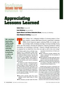
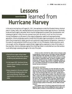
Silicone Contamination Sources and Consequences Silicones which have not been vacuum stripped frequently contain short chain molecules which are volatile and are readily transported onto neighboring surfaces. When these contaminated spacecraft surfaces are exposed to atomic oxygen in low Earth orbit (LEO) the silicones oxidize to form silicates. There is also a tendency to trap hydrocarbons on the surface during the silicate formation. The resulting deposit can form an atomic oxygen protective coating that can darken as a result of solar radiation exposure. Evidence of the consequence of silicone contamination was clearly shown on selected samples flown on LDEF as shown in figure 1 where several samples liberated volatile silicones. In figure 1, some of the volatile silicones formed deposits on the sample holder plate and subsequently became oxidized by atomic oxygen in areas where the surface was not shadowed from atomic oxygen arrival by the samples. The oxides are silicates that stay fixed on the surface only to darken in the ultraviolet solar illumination. Where the silicone volatiles deposit and are not exposed to atomic oxygen, they gradually re-evaporate and no darkening results (hence the light boundary to the right of the samples, shown in the enlarged photo area). These silicate deposits can also shield other samples from atomic oxygen attack, which can adversely alter the outcome of the experiment. In November of 1997 Russian cosmonauts removed and retrieved a non-articulating foldable panel solar array from the Mir core module after 10.4 years in LEO and returned it for an international cooperative analysis (refs. 6 and 7). The solar array panels included a clad structure of solar cells, fiber glass scrim, cover glasses, optical solar reflectors and an open weave organic fabric coated with BF-4 adhesive. Silicone adhesives and thread sutures were used to clad the solar array structure together. Over time, volatile silicones evolved from thread suture holes surrounding the solar cells on both sides of the solar array. Figure 2 shows photographs of the resulting silica deposits on the front and back of Mir solar cells resulting from atomic oxygen oxidization of the silicones that had been transported in the gaseous phase onto neighboring surfaces. The thick contamination appears as a white diffuse deposit. Although the solar array did not significantly degrade in performance from the silicate contamination, there was significant darkening of the optical solar reflector surfaces and neighboring thermal control white paint surfaces. This solar array technology was also used for the Russian supplied solar array for the ISS. Thus, silicone evolution onto surfaces and experiments on ISS from hardware such as this may result in contamination that could affect atomic oxygen erosion and solar absorptance.
Figure 1.—Post flight photograph of Solar Array Materials Passive LDEF Experiment AO171 which exposed silicone RTV-511 samples (the lighter shade samples) to an atomic oxygen fluence of 7.17×10²¹ atoms/cm2 with the atoms arriving from the upper left at an angle of 38° from normal incidence (ref. 2).
NASA/TM—2008-215264
3
(a)
(b)
Figure 2.—Oxidized silicone contamination on solar cells from a MIR solar array retrieved after 10.4 years in LEO. (a) Oxidized silicone contamination near suture sites on the front surface of solar array up to 4.6 microns thick. (b) Oxidized silicone contamination on back surface solar reflector showing tape peeled area where contaminants between 1.06 and 1.24 microns thick were removed.
Table II shows the large variation in silicate contamination on surfaces from experiments placed at different locations on ISS. The MISSE PEC 2 had two orders of magnitude less contaminant thickness than the Japanese JAXA three experiment units (units 1 to 3) (refs. 8 and 9). This is probably due to differences in the total arrival of silicones based on each experiment’s respective view of and distances to contaminant sources on ISS. TABLE II.—SILICATE CONTAMINATION ON ISS EXPERIMENT SURFACES Silicate contaminant Duration of exposure, Silicate contaminant thickness, years thickness/years, nm nm MISSE 2, Tray 1 ram facing 1.3 to 1.4 3.99 0.326 to 0.351 JAXA Unit 1 30.0 0.863 34.8 Unit 2 75.0 2.37 31.7 Unit 3 93.5 3.84 24.3 Location
The lesson learned concerning silicone contamination is that one needs to be careful to avoid self contamination as well as be out of the view of sources of silicone to be sure that atomic oxygen does not produce silica deposits that can affect erosion yields or cause changes in solar absorptance.
Scattering of Atomic Oxygen It has long been suspected and predicted that a portion of the atomic oxygen arriving at a surface will scatter with partial accommodation from surfaces that the atomic oxygen reacts with, as well as from nonreactive surfaces (such as most metal oxides) (refs. 10 to 12). However, only recently, has quantifiable scattering data been available from the results of a small scattering chamber flown on MISSE 2. The experiment consisted of a 2.54 cm diameter scattering chamber containing a SiO2 coated (on the RAM facing surface only) polyimide Kapton H disk with a 3.05 mm diameter aperture that allowed atomic
NASA/TM—2008-215264
4
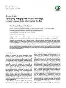
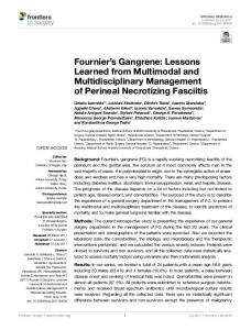
oxygen to enter the chamber and scatter off of an aluminum disk and then react with the Kapton on the bottom of the aperture disk. The bottom of the aperture disk also had many microscopic salt particles attached, which served as protective areas from scattered atomic oxygen attack (fig. 3). By washing off the salt particles and using profilometry, the amount of atomic oxygen erosion was measured as a function of ejection angle. Although cosine (or Lambertian) scattering had been expected, the results indicated that normal incident atomic oxygen scattered in a rather narrow angular distribution, at approximately 45° from normal. The scattered atomic oxygen produced a surprisingly high effective erosion yield which was 21.8 percent of that of RAM atomic oxygen for Kapton H polyimide as shown in figures 4 and 5. The lesson learned is that atomic oxygen does not scatter in a cosine distribution or in a specular direction but instead at 45° from normal for aluminum. This means that one may need to be careful to consider scattered atomic oxygen erosion of materials depending upon the particular geometry of a spacecraft. O
SiO2
Kapton
NaCl
Aluminum
1 cm
(a)
(b)
Figure 3.—MISSE-2 atomic oxygen scattering chamber experiment. (a) Post flight photograph. (b) Section view drawing. Incoming Atomic Oxygen
0.006 0.005 0.004 0.003 0.002 0.001 0.000
Figure 4.—Kapton H butte remaining at site of protective salt particle.
NASA/TM—2008-215264
Figure 5.—Atomic oxygen erosion as a function of ejection angle.
5
Sample Holder Geometry The geometry of sample holders can influence the flux of atomic oxygen impinging upon samples. The typical MISSE sample trays with chamfered circular apertures can allow atomic oxygen to scatter from the chamfered surfaces onto the samples, thus locally increasing the flux impinging on the samples as shown in figure 6. A consequence of the perimeter scattered atomic oxygen is that the erosion around the sample perimeter is greater than in the central area. An example of this is shown in figure 7 for measurements of the MISSE 2 PEACE polyethylene oxide sample. If the atomic oxygen is arriving off normal, then there will be a variation in flux concentrations around the perimeter of each sample depending upon the scattering geometry. As can be seen in figure 8 two of the MISSE 2 samples peeled up from their lower left edge. Atomic oxygen was found to be arriving at 8° from normal and coming from the upper right in the photograph. Thus, there appears to be a greater flux concentration from atomic oxygen that impinges closer to perpendicular from the chamfered surface. For the MISSE 2 trays with circular 2.54 cm diameter samples, the chamfer was at 45° and the lip was 0.763 mm thick. The maximum possible additional fluence for 2.54 in. diameter samples caused by atomic oxygen scattering would be ~15 percent and, based on the previously discussed scattering chamber experiments, more likely ~3.3 percent. Thus, the concern is not relating to a higher average fluence but rather of sample peeling and potential release prior to full erosion of samples, which could lead to incorrect erosion yields. The whole problem of flux concentration and premature peeling could be eliminated if a reverse chamfer was used on the sample holders which would not allow scattering of atomic oxygen on to the surface of the samples. A potential disadvantage of this would be the loss of intimate contact at the edge of the sample for profiling purposes, which would not be a concern for mass loss measurements. The lesson learned is that sample holder chamfers can be a source of flux concentrations, which can cut out the perimeter of samples, and in some cases cause the samples to roll up or potentially be released prior to the full erosion of the sample. The problem could be eliminated by using a reverse chamfer on the sample holder.
Preflight
Aluminum
Post flight Polymer
Not to scale
Figure 6.—Flux concentration from chamfered MISSE sample holders.
NASA/TM—2008-215264
Figure 7.—Comparison of pre and post flight surface profiles for polyethylene oxide sample.
6
Figure 8.—MISSE 2 Tray 1 E5 showing 2 films peeling up on their lower-left side.
Documentation of Orientation of Samples With Respect to Atomic Oxygen RAM Direction Understanding the exact orientation of atomic oxygen arrival, or arrival of contaminants, can be very helpful in interpretation of environmental degradation results. Often exact information can be found if one documents the orientation of samples prior to removal from experiment trays. However, once the samples have been removed the opportunity to do this is lost. The exact orientation of the MISSE 2 atomic oxygen scattering chamber lid was documented. This allowed the determination that atomic oxygen had drilled holes that were 8° off of normal incidence and coming from the upper left of the figure 8 photograph (ref. 12). The knowledge of this off-angled atomic oxygen flux enabled an explanation for the preferential cutting out of thin samples on the lower left perimeter, as shown in figure 8, by atomic oxygen scattered from the lower left chamfer on the circular sample holders. The lesson learned is to either mark samples for orientation or photo-document them to allow their orientation during flight to be known for post flight analysis.
Duration Between Retrieval and Tensile Testing The duration of time between retrieval of samples from space and ground laboratory tensile testing can have a significant impact on the elongation-to-failure for fluorinated ethylene propylene (FEP), and possibly other polymers, that have been exposed to the LEO environment. For example, samples of 0.127 mm thick silvered-FEP (Ag-FEP) retrieved from the wake side (rows 1 and 4) of the LDEF in January 1990, and aluminized-FEP (Al-FEP) from the HST retrieved in December 1993, indicated a significant reduction in elongation-to-failure as time progressed beyond the retrieval dates as shown in figure 9 (ref. 13). Samples were taken from near-neighbor locations in both cases.
NASA/TM—2008-215264
7
LDEF Ag/FEP
Elongationto-failure
HST Al/FEP
100
100
90
90
80
80
70
70
60
60
Elongationto-failure
50 40
50 40
30
30
20
20
10
10
0
0