INTERNATIONAL JOURNAL FOR NUMERICAL METHODS IN ENGINEERING Int. J. Numer. Meth. Engng 2017; 111:493–500 Published online 8 February 2017 in Wiley Online Library (wileyonlinelibrary.com). DOI: 10.1002/nme.5483
Localization aligned weakly periodic boundary conditions Erik Svenning*,† , Martin Fagerström and Fredrik Larsson Division of Material and Computational Mechanics, Department of Applied Mechanics, Chalmers University of Technology, Gothenburg, Sweden
SUMMARY When computing the homogenized response of a representative volume element (RVE), a popular choice is to impose periodic boundary conditions on the RVE. Despite their popularity, it is well known that standard periodic boundary conditions lead to inaccurate results if cracks or localization bands in the RVE are not aligned with the periodicity directions. A previously proposed remedy is to use modified strong periodic boundary conditions that are aligned with the dominating localization direction in the RVE. In the present work, we show that alignment of periodic boundary conditions can also conveniently be performed on weak form. Starting from a previously proposed format for weak micro-periodicity that does not require a periodic mesh, we show that aligned weakly periodic boundary conditions may be constructed by only modifying the mapping (mirror function) between the associated parts of the RVE boundary. In particular, we propose a modified mirror function that allows alignment with an identified localization direction. This modified mirror function corresponds to a shifted stacking of RVEs, and thereby ensures compatibility of the dominating discontinuity over the RVE boundaries. The proposed method leads to more accurate results compared to using unaligned periodic boundary conditions, as demonstrated by the numerical examples. Copyright © 2016 The Authors. International Journal for Numerical Methods in Engineering Published by John Wiley & Sons Ltd. Received 5 September 2016; Revised 24 November 2016; Accepted 24 November 2016 KEY WORDS:
computational homogenization; weakly periodic boundary conditions; aligned periodicity; multiscale modeling
1. INTRODUCTION In numerical simulations, the effective behavior of a heterogeneous microstructure is often predicted using computational homogenization [1, 2], whereby the homogenized response is computed from a representative volume element (RVE) with suitable boundary conditions (BCs). A popular choice of BCs, which often works well, is to apply strong periodic BCs on the RVE [3, 4]. However, such BCs may be inaccurate whenever the topology and/or the response of the microstructure is not aligned with the periodicity directions. One important special case is when cracks or localization bands are present. The response of the RVE, now representative typically for the response along the effective discontinuity, will be strongly constrained by the choice of periodicity directions. As a remedy, Coenen et al. [5, 6] proposed to use percolation path aligned BCs, where strong periodic BCs are aligned to the dominating localization direction in the microstructure. Because strong periodic BCs require a periodic mesh, Larsson et al. [7] proposed to instead impose micro-periodicity in a weak sense, leading to a mixed formulation with displacements and *Correspondence to: Erik Svenning, Division of Material and Computational Mechanics, Department of Applied Mechanics, Chalmers University of Technology, Gothenburg, Sweden. † Email:
[email protected] This is an open access article under the terms of the Creative Commons Attribution-NonCommercial-NoDerivs License, which permits use and distribution in any medium, provided the original work is properly cited, the use is non-commercial and no modifications or adaptations are made. Copyright © 2016 The Authors. International Journal for Numerical Methods in Engineering Published by John Wiley & Sons Ltd.
494
E. SVENNING, M. FAGERSTRÖM AND F. LARSSON
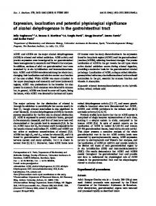
Figure 1. Representative volume element with boundary divided into an image part Γ+□ and a mirror part Γ−□ , with standard mirror function (a) and shifted mirror function (b), where the shifting distance is given by s = l□ ∕ tan 𝛼. The symbols denote related points on Γ+□ and Γ−□ .
boundary tractions as unknowns. This approach also has the advantage that the traction approximation can be adapted to the problem at hand, for example, by accounting for cracks intersecting the RVE boundary [8], in order to gain improved convergence with increasing RVE size. However, artificial constraining may still occur when cracks or localization bands are not aligned with the periodicity directions. In the present work, we show that the weakly periodic BCs proposed in [7] can conveniently be aligned with the dominating localization direction. Interestingly, it turns out that only the mirror function, which relates points on the image and mirror parts of the RVE boundary (as shown in Figure 1(a)), needs to be modified. To be specific, the modified mirror function corresponds to a shifted stacking of RVEs that ensures compatibility of the effective discontinuity over the RVE boundaries. Hence, the weak format of periodicity allows alignment to a localization direction without modifying the weak form or the discretization. Even though alignment of periodic boundary conditions can be achieved also on strong form, we believe the weak format to be a very convenient and versatile setting for constructing boundary conditions that are adapted to the problem at hand. The remainder of the paper is organized as follows: Weakly periodic boundary conditions are briefly reviewed in Section 2.1, followed by a discussion on the construction of the modified mirror function in Section 2.2. Two numerical examples showing the improved performance of the modified mirror function compared with the unmodified mirror function are given in Section 3, and the remarks in Section 4 conclude the paper. 2. THEORY 2.1. Weakly periodic boundary conditions To establish the weak format, consider computational homogenization of an RVE using weakly periodic BCs [7, 8]. To apply such BCs, the RVE boundary is first divided into an image part Γ+□ and a mirror part Γ−□ as indicated in Figure 1(a). Furthermore, a mirror function 𝝋per ∶ Γ+□ → Γ−□ is introduced, such that points on Γ+□ and Γ−□ are associated to each other according to x− = 𝝋per (x+ ). Using this mirror function, the jump between a point x + on Γ+□ and the associated point x− = 𝝋per (x+ ) on Γ−□ is defined as def
[[u]]□ = u+ − u− = u(x+ ) − u(𝝋per (x+ )) on Γ+□ . Copyright © 2016 The Authors. International Journal for Numerical Methods in Engineering Published by John Wiley & Sons Ltd.
Int. J. Numer. Meth. Engng 2017; 111:493–500 DOI: 10.1002/nme
LOCALIZATION ALIGNED WEAKLY PERIODIC BOUNDARY CONDITIONS
495
Assuming small strains, quasistatic loading, and zero body force, the microscale problem then reads as follows: For a given macroscopic strain 𝝐 and position x, find u ∈ U□ and t𝜆 ∈ T□ such that a□ (u, 𝛿u) − d□ (t𝜆 , 𝛿u) = 0∀𝛿u ∈ U□ , [ ]) ( −d□ (𝛿t𝜆 , u) = −d□ 𝛿t𝜆 , 𝝐 · x − x ∀𝛿t𝜆 ∈ T□ , { U□ =
[ ( )]d v ∈ H1 Ω□ ,
(1)
} ∫Γ□
v dΓ = 0
,
[ ( )]d } , t ∈ L2 Γ+□
(2)
{ T□ =
(3)
where we introduced the expressions ] [ 1 a□ (u, 𝛿u) = 𝛔 ∶ 𝛆 [𝛿u] dΩ − t · [[𝛿u]] dΓ , |Ω□ | ∫Ω ∫Γ+ | | □ □,int def
def
d□ (t𝜆 , 𝛿u) =
1 t · [[𝛿u]]□ dΓ, |Ω□ | ∫Γ+ 𝜆 | | □
(4)
(5)
( ) and where L2 Γ+□ denotes the space of square integrable functions on Γ+□ . In the aforementioned def
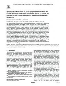
equations, we also introduced [[u]] = u+ − u− , representing the discontinuity over the faces of a crack inside the domain Ω□ , and Γ+□,int = Γ+int ∩ Ω□ , representing the part of the internal boundary located inside Ω□ . Furthermore, 𝝐 = [u ⊗ 𝛁]sym is the engineering strain, 𝝈 = 𝝈 (𝝐) is the Cauchy stress, t = t ([[u]]) is the traction on crack faces in the material, and t𝜆 is the traction on the RVE boundary. See the work of Svenning et al. [8] for further details. When solving Equation (1), different choices for 𝝋per are possible. In particular, 𝝋per can be constructed to avoid artificial crack closure on the boundary as discussed in the following sections. 2.2. Constructing the mirror function 𝝋per The standard choice for the mirror function, which is used by [7, 8] among many others, is to map points along horizontal or vertical lines as shown in Figure 1(a). However, as pointed out by several researchers [5, 9, 10], this choice leads to inaccurate results in some situations. In particular, it works well if cracks or localization bands are aligned with the periodicity directions, whereas artificial crack closure occurs on the RVE boundary for cracks that are not aligned with these directions. This standard mirror function, which is shown in Figure 1(a) and corresponds to stacking RVEs as shown in Figure 2(b), can be explicitly expressed as ) ( 𝝋per l□ , y = (0, y), ( ) (6) 𝝋per x, l□ = (x, 0), where l□ denotes the side length of the RVE. As can be seen from Equation (6), this mirror function maps point along horizontal or vertical lines. To develop an alternative to the standard mirror function given by Equation (6), now assume that a dominating crack or localization band direction exists as indicated in Figures 1(a) and 2(b). Then, we may consider a shifted stacking as shown in Figure 2(c). Even though the crack shown in Figure 2(a) passes through the RVE center, we remark that this shifted stacking can be applied Copyright © 2016 The Authors. International Journal for Numerical Methods in Engineering Published by John Wiley & Sons Ltd.
Int. J. Numer. Meth. Engng 2017; 111:493–500 DOI: 10.1002/nme
496
E. SVENNING, M. FAGERSTRÖM AND F. LARSSON
Figure 2. A representative volume element (RVE) with a crack (a), subjected to standard stacking (b), and shifted stacking (c).
also for cracks that do not pass through the center of the RVE. Using the shifted stacking, the crack pattern is compatible over RVE boundaries, as opposed to when using the standard stacking. This compatibility will prevent artificial crack closure on RVE boundaries. To obtain the shifted stacking shown in Figure 2(c), for a crack orientation as indicated in Figure 2(a) with 45◦ < 𝛼 < 90◦ , the mirror function is modified as shown in Figure 1(b), where some points on Γ+□ are no longer mapped along vertical or horizontal lines. The explicit expression for 𝝋per as shown in Figure 1(b) is given by 𝝋per (l□ , y) = (0, y), 𝝋per (x, l□ ) = (l□ − s + x, 0) if 0 ⩽ x < s, 𝝋per (x, l□ ) = (x − s, 0) if s ⩽ x ⩽ l□ ,
(7)
where the shifting distance is given by s = l□ ∕ tan 𝛼. Clearly, we may carry out the same procedure also for cracks with 𝛼 < 45◦ , whereby the RVEs would be shifted in vertical direction rather than horizontal direction. Using the expression given by Equation (7), we may obtain aligned periodic boundary conditions on weak form by only modifying the mirror function 𝝋per . We emphasize, again, that the shifting distance s depends only on 𝛼 and l□ . Hence, the shifting is valid also for cracks that do not pass through the center of the RVE. We remark that weakly periodic boundary conditions can be shown to fulfill the Hill –Mandel condition as well as average stress and strain relations (cf. [7]). The proof does not explicitly assume that 𝝋per takes the form given in Equation (6) and, hence, the homogenization relations are fulfilled also for the shifted mirror function proposed in Equation (7). 3. NUMERICAL EXAMPLES 3.1. Preliminaries In this section, we give two numerical examples in order to demonstrate the convergence with increasing RVE size and the effect of crack orientation. In the examples, we consider an isotropic and linear elastic bulk material in plane strain with Young's modulus E = 210 × 103 MPa and Poisson's ratio 𝜈 = 0.3. For the cracks, we consider an isotropic and linear elastic cohesive zone model that gives the traction in terms of the displacement jump as t = k[[u]], where k is the stiffness of the cohesive zone. In the examples presented in the succeeding sections, we set k = 1 × 10⁶ N mm − 3 . Weakly periodic boundary conditions are used, with a traction approximation that is piecewise constant over two displacement elements. (See the work of Svenning et al. [8] for a discussion on the choice of suitable traction approximation.) Copyright © 2016 The Authors. International Journal for Numerical Methods in Engineering Published by John Wiley & Sons Ltd.
Int. J. Numer. Meth. Engng 2017; 111:493–500 DOI: 10.1002/nme
LOCALIZATION ALIGNED WEAKLY PERIODIC BOUNDARY CONDITIONS
497
3.2. Convergence with increasing representative volume element size To show that the proposed aligned BCs work well for cases when the use of standard periodic BCs leads to inaccurate results, we consider a specimen with inclined cracks as shown in Figure 3. More precisely, the angle between the cracks and the vertical axis is 3◦ , and the horizontal distance between the cracks is 0.01 mm. For this geometry, we study the convergence of the homogenized stress with increasing RVE size by extracting RVEs of different sizes as shown in the figure. The RVE is subjected to a macroscopic strain of 𝝐 xx = 1 and 𝝐 xy = 𝝐 yy = 0. As output from the simulations, we choose to monitor 𝜎 xx . Simulations are performed for RVEs of different sizes, ranging from l□ = 0.01 mm to l□ = 0.64 mm. Two sets of simulations are performed, one set using the standard mirror function and one using the shifted mirror function.
Figure 3. Representative volume elements (RVEs) considered in Example 3.2, sampled from a large specimen with linear elastic bulk material and inclined cracks. The angle between the cracks and the vertical axis is 3◦ .
Figure 4. Deformed shape of the smallest representative volume element considered in Example 3.2 using standard mirror function (left) and shifted mirror function (right). The deformation is scaled by a factor of 0.1. Copyright © 2016 The Authors. International Journal for Numerical Methods in Engineering Published by John Wiley & Sons Ltd.
Int. J. Numer. Meth. Engng 2017; 111:493–500 DOI: 10.1002/nme
498
E. SVENNING, M. FAGERSTRÖM AND F. LARSSON
The deformed shapes of the smallest RVE, computed with the two different mirror functions, are shown in Figure 4. As can be seen, the standard mirror function enforces unphysical crack closure on the RVE boundary, leading to stress concentrations on the boundary. On the other hand, the shifted mirror function allows crack opening on the boundary and predicts a smooth stress field. This behavior has a strong influence on the homogenized stress as shown in Figure 5. Using the standard mirror function, the RVE needs to be as large as l□ = 0.32 mm to obtain reasonably converged results. On the other hand, the shifted mirror function leads to converged results already for the smallest RVE with l□ = 0.01 mm. Hence, we conclude that the shifted mirror function leads to a dramatic accuracy improvement for smaller RVE sizes. 3.3. Effect of crack orientation To compare the standard mirror function and the shifted mirror function for different crack orientations, consider the RVE with side length l□ = 1 × 10⁻⁴ mm shown in Figure 6(a). For the loading of the RVE, we apply a macroscopic strain in the x-direction, given by 𝝐 xx = 1 × 10⁻³ and 𝝐 yy = 𝝐 xy = 0.
Figure 5. Convergence with increasing representative volume element size for a pattern of inclined cracks (Example 3.2).
Figure 6. Geometry (a) and results (b) for Example 3.3. Homogenized stress in a representative volume element with a crack under prescribed uniaxial strain versus the orientation of the contained crack. Copyright © 2016 The Authors. International Journal for Numerical Methods in Engineering Published by John Wiley & Sons Ltd.
Int. J. Numer. Meth. Engng 2017; 111:493–500 DOI: 10.1002/nme
LOCALIZATION ALIGNED WEAKLY PERIODIC BOUNDARY CONDITIONS
499
For this example, the solution can be computed analytically. For 𝛼 = 0◦ , the crack is parallel to the loading direction, and hence, the material behaves as if the crack were not present. For 𝛼 > 0◦ , the material will show softer response for increasing 𝛼, because of an increased crack opening. With the chosen material parameters, the analytical solution is 𝜎 xx = 2.31 × 10² MPa for 𝛼 = 0◦ and 𝜎 xx = 9.9965 × 10⁻² MPa for 𝛼 = 90◦ . When rotating the crack from 𝛼 = 0◦ to 𝛼 = 90◦ , the analytical solution is a continuously decreasing stress response. The computed stress response and the analytical solution are shown in Figure 6. We first note that the stresses computed with the standard mirror function and the shifted mirror function coincide for 𝛼 = 0◦ , 𝛼 = 45◦ , and 𝛼 = 90◦ . This is expected: no artificial crack closure occurs for cracks aligned with the periodicity directions or aligned 45◦ to the periodicity directions when using the standard mirror function. However, the standard mirror function overpredicts the stress for other values of 𝛼. In particular, using the standard mirror function leads to a higher stress for 𝛼 = 60◦ than for 𝛼 = 45◦ . This is unphysical. Furthermore, the standard mirror function overpredicts the stress by roughly three orders of magnitude for 𝛼 = 85◦ . In contrast, the shifted mirror function shows excellent agreement with the analytical solution for all values of 𝛼.
4. CONCLUSIONS In this work, aligned periodic boundary conditions on weak form are discussed. Using a weak format of periodicity, we show that the weakly periodic boundary conditions can be aligned with a dominating crack direction in a very convenient way: only the mirror function, describing the mapping between the image and mirror parts of the RVE boundary, needs to be modified. Even though the weakly periodic format adopted in the present work requires implementation and solution of a mixed finite element problem, we believe that this format is particularly well suited for alignment of the periodicity, because the method (i) does not require a periodic mesh in the RVE and (ii) allows the traction discretization to be adapted to the problem at hand. It would be possible to apply the modified mirror function also to periodic boundary conditions on strong form. However, this would require either ensuring that the mesh is periodic with respect to the modified mirror function, or that other techniques for treating non-matching meshes (e.g., tie constraints [11]) are adopted. The numerical examples demonstrate that the artificial overconstraining occurring for conventional (weakly) periodic boundary conditions is alleviated by shifting the mirror function as proposed in the present work. The key to success in alleviating the overconstraining is that the modified mirror function corresponds to a shifted stacking of RVEs, thereby ensuring compatibility of the dominating crack over RVE boundaries. In the present work, we have focused on the alignment of the periodicity within the setting of weak periodicity. To maintain this focus, we have assumed that the direction of a dominating crack or localization band has, in some way, been identified a priori. To overcome this limitation, a natural extension is to combine the present work with suitable techniques for identifying a dominating crack direction (see, e.g., [5, 6] for an interesting alternative). Future work involves extending the method proposed here to 3D, which is conceptually straightforward. The major difference is that the 3D case requires shifting in two directions, whereas shifting in one direction is sufficient for the 2D case as demonstrated in the present work. In summary, we have proposed a method for aligning weakly periodic boundary conditions to a dominating crack direction. The proposed method is practical from a computational perspective, because no modifications to the weak form or the discretization are necessary. ACKNOWLEDGMENTS
The project is financially supported by the Swedish Research Council (www.vr.se) under contract 2012-3006. Copyright © 2016 The Authors. International Journal for Numerical Methods in Engineering Published by John Wiley & Sons Ltd.
Int. J. Numer. Meth. Engng 2017; 111:493–500 DOI: 10.1002/nme
500
E. SVENNING, M. FAGERSTRÖM AND F. LARSSON REFERENCES
1. Geers M, Kouznetsova V, Brekelmans W. Multi-scale computational homogenization: trends and challenges. Journal of Computational and Applied Mathematics 2010; 234(7):2175– 2182. 2. Zohdi T, Wriggers P. A model for simulating the deterioration of structural-scale material responses of microheterogeneous solids. Computer Methods in Applied Mechanics and Engineering 2001; 190(22-23):2803– 2823. 3. Fish J, Shek K, Pandheeradi M, Shephard MS. Computational plasticity for composite structures based on mathematical homogenization: theory and practice. Computer Methods in Applied Mechanics and Engineering 1997; 148(1-2):53– 73. 4. Miehe C, Koch A. Computational micro-to-macro transitions of discretized microstructures undergoing small strains. Archive of Applied Mechanics (Ingenieur Archiv) 2002; 72(4-5):300– 317. 5. Coenen E, Kouznetsova V, Geers M. Novel boundary conditions for strain localization analyses in microstructural volume elements. International Journal for Numerical Methods in Engineering 2012; 90(1):1– 21. 6. Coenen EWC, Kouznetsova VG, Bosco E, Geers MGD. A multi-scale approach to bridge microscale damage and macroscale failure: a nested computational homogenization-localization framework. International Journal of Fracture 2012; 178(1-2):157– 178. 7. Larsson F, Runesson K, Saroukhani S, Vafadari R. Computational homogenization based on a weak format of microperiodicity for RVE-problems. Computer Methods in Applied Mechanics and Engineering 2011; 200(1-4):11– 26. 8. Svenning E, Fagerström M, Larsson F. Computational homogenization of microfractured continua using weakly periodic boundary conditions. Computer Methods in Applied Mechanics and Engineering 2016; 299:1– 21. 9. Mesarovic SD, Padbidri J. Minimal kinematic boundary conditions for simulations of disordered microstructures. Philosophical Magazine 2005; 85(1):65– 78. 10. Talebi H, Silani M, Bordas SPA, Kerfriden P, Rabczuk T. A computational library for multiscale modeling of material failure. Computational Mechanics 2013; 53(5):1047– 1071. 11. Yuan Z, Fish J. Toward realization of computational homogenization in practice. International Journal for Numerical Methods in Engineering 2008; 73(3):361– 380.
Copyright © 2016 The Authors. International Journal for Numerical Methods in Engineering Published by John Wiley & Sons Ltd.
Int. J. Numer. Meth. Engng 2017; 111:493–500 DOI: 10.1002/nme