Jul 20, 2001 - electron thermal motion under conditions of the anomalous skin effect. Analysis of the electron energy distri- bution based on the existence of ...
PHYSICAL REVIEW E, VOLUME 64, 026406
Lorentz force effects on the electron energy distribution in inductively coupled plasmas V. A. Godyak and B. M. Alexandrovich OSRAM SYLVANIA, Beverly, Massachusetts 01915
V. I. Kolobov CFD Research Corporation, Huntsville, Alabama 35805 共Received 27 March 2001; published 20 July 2001兲 Depletion of the electron energy distribution function by slow electrons in the skin layer has been observed in experiment in a cylindrical inductive discharge with a flat coil at low frequency and low gas pressure. The origin of the effect lies in the dependence of the ponderomotive force 共caused by the rf magnetic field兲 on the electron thermal motion under conditions of the anomalous skin effect. Analysis of the electron energy distribution based on the existence of adiabatic invariants for collisionless electron motion at low frequencies reveals enhanced anisotropy and time dependence of the electron distribution function due to strong rf magnetic fields and a polarization electrostatic potential at twice the driving frequency. The electron energy distributions calculated in the skin layer using experimentally measured electromagnetic fields and rf and dc potential profiles are in reasonable agreement with the experimental electron distributions. DOI: 10.1103/PhysRevE.64.026406
PACS number共s兲: 52.80.⫺s, 52.65.⫺y
I. INTRODUCTION
Inductively coupled plasmas 共ICPs兲 are widely used for semiconductor processing and lighting technology. In these applications, ICPs are produced in a variety of gas mixtures at pressures between a fraction of a mTorr and hundreds of mTorr in chambers with characteristic sizes 1–10 cm using both continuum and pulsed power operating regimes. The ICPs have been driven over a wide range of frequencies varying from tens of Hz to tens of mHz 关1兴. At low frequencies, ferromagnetic cores have to be used to enhance the magnetic field. A wide variety of sources with different coil geometry have been developed including cylindrical spiral and stove top planar coils driven at single or multiple frequencies. Multicoil ICPs are being developed to maintain a spatially uniform plasma over large surfaces. The physics of an ICP has been a subject of active research in both industry and academia. It has been demonstrated that at low gas pressure, the electron kinetics can be adequately described in terms of the total electron energy ⫽w⫹eU e 共the sum of the kinetic energy w and the potential energy in the dc electrostatic field eU e ). Due to the very small energy loss in elastic collisions of electrons with heavy neutrals, the total electron energy is an approximate invariant of the electron motion. Thus, in low pressure discharges, the electron energy probability function 共EEPF兲 f 0 depends solely on the total electron energy and EEPFs, measured at different spatial positions, coincide with each other when shifted by the local value of the electrostatic potential 关2– 4兴. This EEPF feature 共referred as nonlocal kinetics兲 has been observed in numerous experiments in capacitive and inductive rf discharges 关5–12兴. As a rule, the EEPFs deviate from Maxwellian and often exhibit a complex structure depending on the nature of the working gas and on specifics of the electromagnetic field interaction with electrons. In an ICP, due to the relatively high degree of ionization, the body of the EEPF corresponding to electrons with energy less than the excitation energy * 共the elastic energy range兲 is often a 1063-651X/2001/64共2兲/026406共10兲/$20.00
Maxwellian distribution owing to Coulomb interactions among electrons. In the inelastic energy range (⬎ * ) the EEPF can be depleted compared to a Maxwellian distribution due to electron energy loss in excitation, ionization, and 共at the lowest gas pressure兲 due to the escape of fast electrons to the wall. The main interaction of the electromagnetic field with the plasma in inductive discharges takes place in the skin layer of thickness ␦ near the plasma boundary. Depending on gas pressure, plasma density, and driving frequency, the interaction of an electromagnetic field with plasma within the skin layer can be local or nonlocal in nature. The collisional 共or/ and very high frequency兲 regime, when electrons pass through the skin layer with many collisions and/or spend 2 1/2 ) 兴 , is the domany rf field periods there 关v th / ␦ ⬍( 2 ⫹ ea main of Joule heating and normal skin effect, where v th ⫽(2T e /m) 1/2 is the electron thermal velocity and ea is the electron-atom collision frequency. The nearly collisionless 2 1/2 ) is the domain of nonlocal regime when v th / ␦ ⬎( 2 ⫹ ea electrodynamics, anomalous skin effect 关13兴, and collisionless electron heating 关14,15兴. Under the conditions of the anomalous skin effect, the current induced by the rf electric field is not determined solely by the local value of the rf field at that point, but depends also on the field profile in the neighborhood of the point 关16兴. Several hot plasma effects have been discovered recently in weakly collisional ICPs, including nonmonotonic field profiles 关17兴 collisionless power dissipation 关18 –21兴, negative power absorption 关22兴, etc. Peculiarities of collisionless heating result in a specific frequency dependence of the EEPF in the weakly collisional regime 关23兴. Static magnetic fields of only a few Gauss may result in a significant modification of the rf field penetration into the plasma 关24兴. Weak static magnetic fields can change the electron heating in an ICP 关25兴 and influence the shape of the EEPF 关26兴. Trends towards lower operating frequency are clearly recognizable in recent ICP developments 关27–29兴. Low frequency operation reduces capacitive coupling and the trans-
64 026406-1
©2001 The American Physical Society
V. A. GODYAK, B. M. ALEXANDROVICH, AND V. I. KOLOBOV
mission line effect in ICP inductors and leads to simplification and lower cost of rf power sources and matching circuits. Scaling ICP sources to larger dimensions is also simplified at low frequencies. The transition to lower operating frequencies enriches the ICP physics due to enhancement of nonlinear interactions between electromagnetic fields and plasma electrons that are usually unimportant at the standard industrial frequency 13.56 MHz. Nonlinear effects in ICP are mainly caused by the rf Lorentz force FL⫽en 关 v⫻B兴 acting on electrons in the skin layer. They bring about a variety of new phenomena discussed in recent literature, including generation of the second harmonic of the electrostatic potential 关30兴 and rf current 关31,32兴, and ponderomotive force effects on the spatial distribution of plasma density and the ambipolar potential 关33兴. It has been shown 关33兴 that ponderomotive effects in an ICP are much smaller than those given by classical formula and that a significant ponderomotive effect is possible only under conditions of the anomalous skin effect. A lower driving frequency results in augmentation of the Lorentz force produced by an rf magnetic field. At frequencies below 1 MHz, the Lorentz force can be much larger than the electric force produced by the induced electric field 关33兴. In an ICP, the Lorentz force is mainly directed normal to the plasma boundary and has a time-independent component and an oscillating component at twice the driving frequency. The time-independent component represents a ponderomotive 共Miller兲 force that pushes electrons and ions out of the skin layer. This force can be described in terms of a ponderomotive potential U p , (Fp⫽⫺enⵜU p ). By adding this potential to the electrostatic 共ambipolar兲 potential, one can expect that the EEPF becomes a function of the new total electron energy, f 0 ⫽ f 0 (w,U e ,U p ). In a macroscopic sense, this corresponds to a ponderomotive modification of the plasma density n and electrical 共ambipolar兲 potential U e , demonstrated recently for a low pressure, low frequency ICP 关33兴. In this paper we present results of an experimental and theoretical study of EEPFs in a low pressure ICP at low driving frequencies where substantial deviations from the ‘‘usual’’ EEPF behavior are observed in the skin layer. II. EXPERIMENTAL SETUP AND MEASUREMENT TECHNIQUE
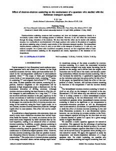
The EEDF measurements were carried out in a cylindrical ICP chamber 共20 cm in diameter and 10.5 cm in length兲 with a quartz window and a planar induction coil shown in Fig. 1 and described in detail in Ref. 关34兴. The measurements were made in an ICP driven at /2 ⫽0.45 and 0.9 MHz in argon at a pressure of 1 mTorr where nonlinear phenomena are well expressed. For comparison, similar measurements were done for 3.39 and 6.78 MHz where nonlinear effects on the EEPF were negligible. The discharge power dissipated in the plasma was found by accounting for losses in the inductor coil and the matching circuit 关34兴. The discharge power was kept constant in these experiments at a level of 200 W. The ICP inductor coil and matching circuit were somewhat different for low frequencies 共0.45 and 0.9 MHz兲 and for high frequencies 共3.39 and 6.78 MHz兲. For all frequencies, the
PHYSICAL REVIEW E 64 026406
FIG. 1. Experimental ICP chamber and rf compensated probe circuitry.
induction coil had the same geometry and dimensions 共3.8 cm ID and 12.7 cm OD兲, and was placed at the same distance from the window. For low operating frequency, the coil consisted of 20 turns of litz wire, while for high operating frequency the coil had only five turns as described in Ref. 关34兴. Langmuir probe measurements of the EEPF have been carried out in this ICP along its axial direction at the discharge axis (r⫽0) and at a fixed radial position (r ⫽4 cm) corresponding to maxima in the radial distributions of the radial rf magnetic field, B r (r) and the radial distributions of the azimuthal rf electric field, E (r). The measurements were made using our Langmuir probe station 关35兴. Low frequency noise suppression, probe circuit resistance compensation, ensemble averaging, and digital processing with adaptive filtering were implemented there to achieve high quality EEPF measurements. The basic plasma parameters, plasma density n, effective electron temperature T e , and electron-atom collision frequency ea were found as corresponding integrals of the EEPF. Additionally, a twodimensional differential magnetic probe 关17,36兴 was used to evaluate the axial distributions of the azimuthal rf electric field E (z) and the current density J (z) at a fixed radial position, r⫽4 cm. Since capacitive coupling was negligible in low frequency operation, no electrostatic screen between the coil and plasma was needed to attain a low rf plasma potential relative to the ground. The measurement of rf plasma potential V r f in the plasma 关34兴 showed that for high frequencies 共3.39–13.56 MHz兲, V r f was much smaller than the electron temperature T e . But at low operating frequencies, considerable oscillations of the electrostatic potential in the skin layer were observed 关30兴, with the second harmonic potential V 2 共shown in Fig. 2兲 being two orders of magnitude larger than the fundamental and all other harmonics. However, in the
026406-2
LORENTZ FORCE EFFECTS ON THE ELECTRON . . .
PHYSICAL REVIEW E 64 026406
FIG. 2. Polarization rf potential V 2 in the skin layer 关30兴.
bulk plasma, far away from the skin layer, V 2 was much smaller than the electron temperature (T e ⫽6 –7 eV) and there was no need to rf compensate the probe to obtain undistorted probe measurements outside the skin layer. Since the large gradient of V 2 in the skin layer much exceeded the azimuthal rf electric field 关30兴, it was impossible to achieve rf compensation of the probe with traditional means 关35,37兴. A relatively large floating electrode needed for rf shunting of the measurement probe would result in unacceptable distortion of the rf field and rf current in the skin layer. To solve this specific problem we developed a rf compensated double probe and corresponding circuitry shown in Fig. 1. Drastic reduction in the impedance of the shunting electrode 共probe兲 relative to plasma 关about (m/M ) 1/2 times, where m and M are the electron and ion masses兴 was achieved by biasing it positively. This allowed for a significant reduction of the shunting electrode to the size of the small Langmuir probe. The probe system shown in Fig. 1 consists of two equal thin cylindrical tungsten wires (l p ⫽5 mm, r p ⫽0.05 mm兲 oriented in the plane of constant z and directed along azimuthal rf electric field E . Both probes are fitted to a quartz two-bore capillary having outer diameter of 0.5 mm and extended length of 2 cm. The capillary is built into a stainless steel tube shaft having diameter of 1.6 mm, in the discharge chamber and 6.35 mm outside the chamber, and fixed on a vacuum-sealed moving stage allowing axial displacement of the probe. It is imperative to keep the probe holder 共quartz capillary and shaft part penetrating the plasma兲 as thin as possible to minimize local and global plasma disturbance. At the end of the probe shaft 共outside the discharge chamber兲 the probe leads were sealed in epoxy and connected to a metal filter box containing a two-channel resonant transformer filter 共shown in Fig. 1兲 tuned to the second harmonic of the driving frequency, 2 . After the filter, the probe leads were connected, respectively, to a dc bias voltage source and to the probe station. The probe system operates as following. One of the probe wire works as a measuring Langmuir probe, while the second serves as a shunting probe equalizing the rf potential of the measuring probe to the plasma rf potential V r f . That is achieved by biasing the reference probe to the dc plasma potential 共where probe resistance to plasma is minimal and its coupling to plasma is maximal兲 and by inductive coupling
the two probes with a 1:1 resonant transformer as shown in Fig. 1. The transformer consists of two bifilar windings 共having inductances L1 and L2 ) on a ferrite pot core and, therefore, provides an ideal coupling between L 1 and L 2 共the rf voltage across each winding is equal to each other兲. Thus, for rf signal, both windings work in parallel as a single coil with inductance L⫽L 1 ⫽L 2 . Being resonant with capacitors C 1 and C 3 , C 4 and the probe wires capacitance C p to the grounded probe shaft (C 3 ⫽C 4 ⰇC 1 ⬇C p ), this inductance forms a resonant tank filter with its resistance R f ⬇2Q L; where Q is the Q factor of the resonant circuit. In our experiment R f was about 380 and 520 k⍀, corresponding to 0.45 and 0.9 MHz, while the impedance of the shunting probe R po for the lowest plasma density in the skin layer (n min ⬇3 ⫻1010 cm⫺3 ) was about 20 k⍀. In the worst case of the largest rf plasma potential (V r f ⬇10 V) and the smallest filter resistance R f , the rf voltage in the sheath of the measuring probe, V sh ⫽V r f R po /(R f ⫹R po )⫽0.5 V, which was negligibly small compared with the electron temperature measured in the skin layer, T e ⫽7 eV. Thus, the condition of an EEDF measurement, undistorted by rf voltage V sh ⬍0.3T e /e, 关37,38兴, was met in this experiment. Here and throughout the paper we use rms values for all oscillatory quantities. III. EXPERIMENTAL RESULTS AND DISCUSSION
Prior to discussing experimental results, let us briefly describe specific features of our ICP at a low operating frequency. At 1 mTorr the discharge is close to the ion free path regime ( i ⬎L,R) with an electron mean free path e being much larger than the chamber length L and radius R. At this condition the ICP operates in a strongly nonlocal regime 共anomalous skin effect兲. Due to the low driving frequency, plasma screening has little effect on the electromagnetic field distribution, which is mainly defined by the chamber geometry. The electromagnetic field distribution with plasma is similar to that in vacuum with characteristic scale for the field decay ␦ ⬇ ␦ 0 ⫽2.42 cm⬇R/3.83⫽2.61 cm, corresponding to the rf electric field distribution in the vacuum chamber 关14,39兴. Here ␦ 0 is the characteristic length of the electric field decay in empty chamber. At 200 W and 1 mTorr, the plasma density and electron temperature in the plasma center (r⫽0, z⫽5 cm) were 1.3⫻1011 cm⫺3 and 6 eV, respectively. These same parameters in the middle of the plasma active zone (r⫽4 cm, z⫽1 cm) were about 5 ⫻1010 cm⫺3 and 7 eV, respectively. From magnetic probe 2 in the skin layer measurements we found that B2 Ⰷ 2 ⫹ ea 关33,40,41兴, where B ⫽eB /m is the electron cyclotron frequency and B is the dominant 共radial兲 component of rf magnetic field in the skin layer. This means that the nonlinear Lorentz force FL⫽en 关 v ⫻B 兴 greatly exceeds the electric force FE⫽enE , where v is the electron rf drift velocity. Thus, under conditions of our experiment, the skin effect in the ICP was not only anomalous but also nonlinear 关15,32,33,40,41兴. The electron energy distributions measured at the axial position of maximal plasma density and in the middle of the skin layer (z⫽1 cm from the window兲, at a fixed radial
026406-3
V. A. GODYAK, B. M. ALEXANDROVICH, AND V. I. KOLOBOV
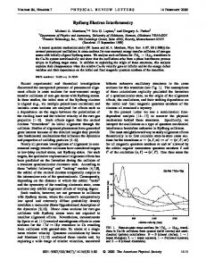
FIG. 3. EEPF measured for 0.45, 0.9, 3.39 and 6.78 MHz at the position of maximum plasma density (z⫽z * ,r⫽4 cm) and in the skin layer (z⫽1 cm, r⫽4 cm兲.
position (r⫽4 cm) are shown in Fig. 3 for different frequencies. The electron energy distribution is given in terms of the EEPF, f 0 () plotted against the total electron energy ⫽w⫹eU e . The EEPF as a function of the electron kinetic energy f 0 (w) is proportional to the measured second derivative of the probe characteristic I p (V), f 0 (w) ⬀d 2 I p /dV 2 . The plasma potential is defined as the probe potential where the second derivative of the probe characteristic crosses zero. As seen in Fig. 3, the shapes of EEPFs in the elastic energy range (⬍ * ), measured at r⫽4 cm, in the point of the maximum plasma density, evolve from concave at high frequency 共with a low energy peak兲 to convex at low frequency. The EEPFs measured at r⫽0 for low frequencies 共not shown here兲 are essentially Maxwellian in the elastic energy range. An enhancement of the EEPF at low electron energy at high frequency is a result of nonlocal electron kinetics specific to electron interactions with electromagnetic fields under conditions of the anomalous skin effect analyzed in 关23兴. At lower frequency, more low energy electrons participate in the heating process in the skin layer resulting in higher temperature and the disappearance of the low energy peak in the EEPF. In the inelastic energy range (⬎ * ) the EEPF slope increases starting at about 20 eV. A depletion of the EEPF with high energy electrons is due to ionization and fast electron escape to the chamber walls whose potential is about 24 V lower than the plasma potential. Such an EEPF structure in inelastic energy range is typical for dc and rf discharges in the Tonks-Langmuir regime ( i ⬎R,L) when direct ioniza-
PHYSICAL REVIEW E 64 026406
FIG. 4. Axial evolution EEPF at different radial positions for 0.45 MHz.
tion and escape to the wall are the major channels of fast electron loss. At higher pressure and/or larger chamber size 共for our experimental device, at argon pressure about 10 mTorr and higher兲, the EEPF depletion starts when the electron energy is close to the excitation energy * . The EEPF measured at 3.39 and 6.78 MHz in different spatial positions 共thus, at different plasma potential U e ) closely coincide for ⬎eU e and ⵜ f 0 (r,)⬇0. This is a very common feature of bounded gas discharge plasmas at low gas pressure when the electron energy relaxation length is much larger than plasma size and is a consequence of nonlocal electron kinetics 关2– 4兴. A small divergence in f 0 (r,) in the vicinity of plasma potential 共small electron kinetic energy兲 measured close to the window is typical for probe measurements at the ICP plasma boundary where a strong rf field is present, and is probably caused by relatively large directed velocity of low energy electrons v approaching their thermal velocity. A different EEPF evolution in the skin layer is seen in Fig. 3 for low driving frequencies 0.45 and 0.9 MHz. Here a significant difference is found for EEPFs measured at different positions, although the plasma potential difference between them is negligibly small, while the corresponding potential difference for both 3.39 and 6.78 MHz is about 2.0 V. Note that the EEPFs corresponding to the maximum plasma density, measured at low frequencies are shifted from ⫽0, while the EEPFs measured at high frequencies begin from ⫽0. This suggests that at low frequencies the maximum plasma density does not coincide with the minimum in the potential energy eU e ⫽0. Shown in Fig. 3, the EEPFs measured at low frequencies
026406-4
LORENTZ FORCE EFFECTS ON THE ELECTRON . . .
PHYSICAL REVIEW E 64 026406
FIG. 6. Axial evolution EEPF at r⫽4 cm for 3.39 MHz.
FIG. 5. Axial evolution EEPF at different radial positions for 0.9 MHz.
look as if they were heavily distorted by the rf voltage across the probe sheath. But the rf filtering in the probe circuit was thoroughly addressed in this experiment and the probe rf voltage was much less than that needed for undistorted EEPF measurement. Note rf probe distortion usually affects the EEPF in the vicinity of the plasma potential and does not change the slope of the EEPF for medium and high electron energies. However, the EEPFs measured in the skin layer at low frequencies diverge over a wide range of electron energies, although the divergence is largest for low energy electrons. The EEPFs measured along axial direction at r⫽4 cm and on the discharge center (r⫽0) are shown in Figs. 4 and 5, correspondingly, for 0.45 and 0.9 MHz. Here, the EEPFs measured between the active plasma boundary (z ⫽0.2 cm) and the position of maximum plasma density (z ⫽z * ) are given on the left side, while the EEPFs measured between z * and the point z⫽9.2 cm, near the passive plasma boundary, are given on the right side. The EEPF divergence takes place only in the area of large electromagnetic field (r⫽4 cm and z⬍z * ), while at z⬎z * and everywhere on the discharge central axis (r⫽0), where there is no electric field, the EEPFs measured at different positions and plasma potentials, coincide with each other. Similar measurements at high frequencies 共see Fig. 6兲 did not show a considerable EEPF divergence in the skin layer, although the rf field there was larger than that at low frequencies. Measurements at lower discharge power showed an even larger divergence of EEPFs measured within the skin layer although the rf field in the skin layer was somewhat smaller at low power. This is shown in Fig. 7 for ICP at 50 W and 0.9 MHz. The weaker divergence at high discharge power 共high plasma
density兲 could be explained by enhanced electron-electron collisions ( ee ⬀n) leading to EEPF Maxwellization. The divergence of EEPFs in the skin layer of a low frequency ICP can be interpreted as the result of ponderomotive effect caused by the nonlinear Lorentz force FL⫽en 关 v ⫻B 兴 . Indeed, since in a cylindrical ICP, E ⫽⫺ ␦ B r and, due to the Ramsauer effect and stochastic electron heating, the azimuthal rf electric field E 共and so the rf drift velocity v ) is a weak function of the frequency 关42兴, the ponderomotive force is nearly inversely proportionally to the driving frequency. It has been shown in calculations 关43兴 that the ponderomotive effect is negligibly small at the industrial frequency 13.56 MHz but may be significant at lower frequencies. The ponderomotive modification of the ambipolar potential U e and the plasma density n distributions in our ICP operated at 1 mTorr of argon gas, at 0.45 MHz has been demonstrated earlier 关33兴 and is illustrated in Fig. 8. Presented here are the axial distributions of U e (z) and n(z) at r⫽4 cm and r⫽0; the plasma density was found by integration of the experimental EEPF given in Fig. 4. At low frequency, 0.45 MHz, the distributions are asymmetric relative to the discharge mid plane, and the position z * of the maximum electron density, and the position z ⬘ of minimum ambipolar potential, do not coincide, while at high frequency 6.78 MHz, both distributions are rather symmetrical, with z * ⫽z ⬘ , 关33兴. The shift between z * and z ⬘ in the skin layer at
026406-5
FIG. 7. Axial evolution EEPF at r⫽4 cm for 0.9 MHz, 50 W.
V. A. GODYAK, B. M. ALEXANDROVICH, AND V. I. KOLOBOV
FIG. 8. Plasma density and potential distribution at different radial positions for 0.45 MHz, 1 mTorr, 200 W 关33兴.
r⫽4 cm, implies an additional ponderomotive force F p ⫽⫺endU p /dz in the plasma equilibrium balance: Te
dn dU e dU p ⫹en ⫹en ⫽0 dz dz dz
共1兲
whose solution is n⫽n 0 exp共 ⫺eU th 兲 ,
共2兲
where U th ⫽U e ⫹U p ⫽(T e /e)ln(n0 /n) is the plasma thermal potential. In the absence of the ponderomotive force (U p ⫽0), Eq. 共2兲 reduces to the conventional Boltzmann equilibrium equation (U th ⫽U e ). The quantities U th and U e found in experiment 关33兴 are plotted in Fig. 9 for r⫽4 cm and r ⫽0. The disparity between U th and U e are clearly seen in the skin layer (r⫽4 cm), while far away of skin layer where electromagnetic field is negligibly small, as well as along the discharge axis where v ⫽0, the Boltzmann equilibrium is well satisfied (U th ⫽U e ). This observation suggests that a considerable ponderomotive effect does exist in our ICP operated at low pressure and low frequency. According to the main principle of nonlocal electron kinetics, the EEPF in the presence of ponderomotive potential U p should be a function of the total electron energy including U p , f 0 ()⫽ f 0 (w⫹U e ⫹U p ). This explains the shift in the energy of the EEPFs measured in the skin layer shown in Figs. 3–5. The change in the shape of EEPFs measured at different positions within the skin layer could be explained by the dependence of U p on electron kinetic energy and by ponderomotive force acting in the radial direction due to the axial component of the rf magnetic field B z that drives slow electrons 共both inwards and outwards兲 from the position r ⫽4 cm corresponding to maximum rf field.
PHYSICAL REVIEW E 64 026406
FIG. 9. Plasma thermal and electrical potential at different radial positions for 0.45 MHz, 1 mTorr, 200 W 关33兴.
A qualitative explanation of the ponderomotive force effect on the EEPF can be offered as follows. The ponderomotive force in an ICP is mainly the averaged Lorentz force that is proportional to the rf current. Under conditions of the anomalous skin effect, due to thermal electron motion 共rf current diffusion兲, the rf current in the skin layer is smaller than that given by the cold 共local兲 plasma theory. The higher the electron thermal velocity is, the smaller the rf current, and Lorentz force are in the skin layer compared to those given by the local theory. Thus, thermal electron motion reduces the ponderomotive force mainly for slow electrons and therefore EEDF in the skin layer should be depleted of slow electrons. It is interesting to note that the ponderomotive potential 共averaged over electron ensemble兲 found from Fig. 9 as the difference between U th and U e appeared to be considerably less than that following from the classical formula for the ponderomotive force derived in the cold plasma 共local兲 approximation. The expression for ponderomotive force in a nonlocal regime ( v th / ␦ Ⰷ , ea ) have been obtained in 关44兴, where it has been shown that ponderomotive force in anomalous skin layer is about v th / ␦ times smaller than that in the local regime. IV. THEORY
A straightforward calculation of the electron energy distribution in a cylindrical low pressure, low frequency ICP featuring nonlocal kinetics, nonlocal and nonlinear electrodynamics requires the solution of a spatially inhomogeneous, time-dependent, and multidimensional Boltzmann equation, which is still today a tremendous task. Among the methods
026406-6
LORENTZ FORCE EFFECTS ON THE ELECTRON . . .
PHYSICAL REVIEW E 64 026406
of solving the Boltzmann equation are particle-in-cell 共PIC兲 methods with Monte Carlo collisions 关45兴, deterministic finite difference methods 关46兴, and semianalytical methods 关47兴. PIC methods suffer from statistical noise and EEPF ‘‘tails’’ are rarely shown in PIC simulations. Deterministic methods resolve all points in phase space with equal accuracy. Currently, they require reducing the dimensionality of the problem by using certain approximations. A commonly used approximation is a two-term spherical harmonic expansion in velocity space that reduces the Boltzmann kinetic equation to a Fokker-Planck equation for an isotropic part of the electron velocity distribution function 共EVDF兲 in a fourdimensional space 共3D1V兲. This approach is adequate for the treatment of the majority of electrons in collisional or very high frequency discharges where the EVDF is weakly anisotropic. Both, high frequency and low frequency 共or pulsed power兲 regimes could well be simulated by this method as long as plasma can be adequately described by local electrodynamics when electron current is a local function of the electromagnetic fields. This corresponds to a collision dominated plasma or to a high frequency regime, when ␦ 2 Ⰷ v th /( ea ⫹ 2 ) 1/2, 共normal skin effect兲. In this regime of local electrodynamics the isotropic part of the EVDF, f 0 is nonlocal, it is defined by the electric field profiles in the space 共around the given point兲 having scale of the order of electron energy relaxation length, while the anisotropic part of EVDF, f1 is a local function of electromagnetic field. 2 For a weakly collisional plasma when ␦ Ⰶ v th /( ea 2 1/2 ⫹ ) , 共domain of nonlocal electrodynamics, anomalous skin effect兲, the two-term spherical harmonic expansion is not entirely adequate because it implies a local relationship between electron current and electromagnetic field. However, as long as the field effect may be considered a small perturbation, the EVDF subdivision into a time-independent isotropic part f 0 and a small oscillating anisotropic addition f1 remains valid. In a weakly collisional warm plasma, the perturbed part of the EVDF, f1 , is also nonlocal, it is strongly affected by the thermal electron motion and depends on field distributions in a vicinity of a given point with dimensions of the order of electron mean free path ⫽ v th / ea . The isotropic part f 0 may be found 共similarly to that in the local electrodynamics regime兲 from a spatially averaged kinetic equation and depends solely on the total electron energy. Thus, using this method, the complexity of the problem is reduced to calculation of the perturbed part of the EVDF that in general case still requires solution of a multidimensional kinetic equation. However, for several one-dimensional cases analytical solutions have been obtained and proved to be useful for the analysis of stochastic electron heating, anomalous skin effect, and other warm plasma effects observed recently in weakly collisional ICP discharges. The traditional perturbation methods are not valid for the EDF treatment in a weakly collisional ICP at low frequency because the perturbed part of the EVDF cannot be considered as a small perturbation. Indeed, with decreasing field frequency, the amplitude of the electron velocity oscillation in the induced electric field may become comparable to or larger than the thermal electron velocity. Moreover, at ⬍ v / ␦ , the Lorentz force becomes even large than the elec-
tric force 关33兴. Thus, substantial perturbations of the EVDF must be expected and the two-term expansion of the EVDF is no longer valid. Of primary interest to this paper is the case when the ions do not respond to the field oscillations ( ⬎ v s / ␦ ⬇2.3 ⫻105 s⫺1 ), forming a steady positively charged background, whereas the electrons follow the field oscillations. Here v s ⫽(T e /M ) 1/2 is the ion sound speed. The Lorentz force in the skin layer produces electron displacement in the direction normal to the plasma boundary 共z direction兲, inducing the polarization electrostatic potential of frequency 2 with the corresponding electric field in axial direction E z2 being much larger than the azimuthal electric field E that maintains the discharge 关30兴. In a sense, ICPs in this regime resemble capacitively coupled plasmas 共CCP兲 since the electromagnetic force is mainly acting normal to the plasma boundary. A quantitative description of electron kinetics in this regime requires solution of the time-dependent Boltzmann equation in a 共2D3V兲 formulation where the two spatial dimensions are radial and axial position, and the three velocity components are v , v r , and v z . To describe qualitatively the observed depletion of the EEPF by slow electrons in the skin layer, we use the approach developed by Cohen and Rognlien in their calculation of the ponderomotive effect and plasma polarization, caused by the Lorentz force, in a ICP skin layer 关48,49兴. The main idea of this approach is to utilize exact integrals of the collisionless electron motion and adiabatic invariants to obtain the EVDF in the skin layer from a given EVDF outside the skin layer. They have obtained a one-dimensional analytical solution to the collisionless Boltzmann equation in the skin layer using conservation of the canonical momentum and existence of the longitudinal adiabatic invariant at v th / ␦ Ⰷ1. We shall use this solution to describe qualitatively the observed EEPF in a two-dimensional ICP driven by a planar coil. Consider a planar case when the electromagnetic fields have only B x and E y components and the z axis is directed normal to the plasma boundary adjacent to the coil. This case resembles the two-dimensional ICP driven by a planar coil where B r and E are the main field components in the skin layer. The integral of the particle motion is the canonical momentum p y ⫽m v y ⫺eA y , where A y is the vector magnetic potential. At low frequencies, using conservation of the longitudinal adiabatic invariant, and assuming a Maxwellian EEPF outside the skin layer, one obtains the electron velocity distribution function f (u y ,u z ,z) in the skin layer: f ⫽C⫻
再
exp共 ⫺u 2y ⫺u z2 ⫺⌽ 兲 ,
u z2 ⫺⌽⫹2u c u y ⫺u 2c ⬎0
exp共 ⫺ 共 u y ⫺u c 兲 2 ⫺⌽ 兲 ,
u z2 ⫺⌽⫹2u c u y ⫺u 2c ⬍0. 共3兲
Here ⌽ denotes dimensionless electrostatic potential in . The upper the plasma, ⌽⫽eU e /T e , and C⫽2n ⫺1/2T ⫺3/2 e inequality in Eq. 共3兲 corresponds to free electrons, the lower inequality corresponds to trapped electrons. Here u⫽ v / v c is a dimensionless velocity, v c ⫽eA y /m is the electron oscillatory velocity, and A y (z, ) denotes the value of the vector magnetic potential at a point z at the moment of electron’s
026406-7
V. A. GODYAK, B. M. ALEXANDROVICH, AND V. I. KOLOBOV
PHYSICAL REVIEW E 64 026406
FIG. 12. Averaged over rf period EVDFs in the u y ⫽0 and u z ⫽0 planes and the isotropic part of the EVDF, f 0 obtained by numerical integration of the EVDF given by Eq. 共3兲.
FIG. 10. The EVDF 共f/C兲 given by Eq. 3 for ⌽(z, )⫽0.
reflection by electromagnetic forces. For a sinusoidal wave, A y (z, )⬀sin . The electrostatic potential ⌽ has a timeindependent 共dc兲 component and a component at 2 . The oscillating component of ⌽ builds up to maintain the quasineutrality of the plasma in the skin layer. The ion displacement in the skin layer during the rf period is negligible for an rf field period smaller than the ion transit time through the skin layer. Thus, ions form an immobile background whereas the electrons respond to the instantaneous values of the electromagnetic forces oscillating along the azimuthal direction with frequency and in the axial direction with frequency 2 . Figure 10 shows the EVDF given by Eq. 共3兲 for ⌽(z, )⫽0. It is seen that the EVDF is depleted with respect to a Maxwellian EVDF at low velocities u⬍u c . The depletion occurs only in the skin layer and results in an anisotropy 共the u y and u z velocity components are affected in a different
FIG. 11. Instant values of the EVDF in the u y ⫽0 and u z ⫽0 planes, f (u z ,0,z, ), and f (0,u z ,z, ) at a point z in the skin layer at a moment t⫽ / of maximum amplitude of A(z, ), and a result of the EVDF averaging over angle in velocity space f 0 (u,z, ).
manner兲 and a time dependency of the EVDF 共since the vector magnetic potential A y oscillates in time兲. To calculate the time independent isotropic part of the EVDF, f 0 that corresponds to the EEPF, f 0 measured in the experiments, the EVDF given by Eq. 共3兲 was averaged over a rf period and over angle in the velocity space u y , u z . Figures 11 and 12 illustrate the procedure of averaging. Figure 11 shows instantaneous values of the velocity distribution in the u y ⫽0 and u z ⫽0 planes, f (u y ,0,z, ) and f (0,u z ,z, ) at a point z in the skin layer at a moment t⫽ / of maximum amplitude of A(z, ), as well as a result of the EVDF averaging over angle in velocity space f 0 (u,z, ); Figure 12 shows the velocity distributions in the u y ⫽0 and u z ⫽0 planes, averaged
FIG. 13. Calculated EEPFs at different axial positions for frequencies 0.45, 0.9, 3.4, and 6.8 MHz.
026406-8
LORENTZ FORCE EFFECTS ON THE ELECTRON . . .
PHYSICAL REVIEW E 64 026406
over an rf period, as well as the isotropic part of the EVDF, f 0 obtained by numerical integration of the EVDF given by Eq. 共3兲. It is seen that f 0 is depleted at low energy compared to a Maxwellian distribution. The calculated EEPFs, f 0 for 0.45, 0.9, 3.4, and 6.8 MHz are shown in Fig. 13. The electron density n and temperature T e used in the calculations, as well as the spatial distributions of the electromagnetic fields E , B r , and electrostatic potential ⌽ 共dc and oscillating parts兲 were taken from the experiment 关30,33兴 partly given in Figs. 2 and 8. The experimentally observed distributions of the azimuthal rf electric field and oscillating part of the electrostatic potential were described by the formula
sence of the potential oscillations, ⌽ z2 ⫽0兲 produces the EEPF depletion in the low energy range starting at velocity u c . In addition, the Lorentz force results in the oscillating potential ⌽ z2 that produces a shift of the EEPF as a whole. A rigorous quantitative description of the observed phenomena requires solution of the Boltzmann equation in the 2D3V formulation.
V. CONCLUSIONS
where E 0 and ⌽ 0 are the azimuthal electric field E and normalized polarization potential ⌽ z2 at the plasma boundary (z⫽0), and ␦ 2 is the characteristic decay length for ⌽ z2 . It is seen from the comparison of the experimental and calculated results that the observed depletion is qualitatively well reproduced by the theory. Different slopes for high energy electrons in the experimental and theoretical EEPFs are due to the assumption 共in calculation兲 of a Maxwellian distribution over the entire electron energy range. The observed depletion of the EEPF in the skin layer is a result of two effects. The Lorentz force by itself 共in the ab-
An rf compensated Langmuir probe has been designed for measurement in rf plasmas with large rf field inhomogeneity. Measurements in the skin layer of a low pressure, and low frequency ICP revealed significant EEPF depletion at low electron energy. The depletion was observed only at low frequencies, when conditions of anomalous and nonlinear skin effect are met. The EEPF depletion was interpreted as a ponderomotive effect caused by the Lorentz force affected by electron thermal motion. Under these conditions, the ponderomotive force in the skin layer mainly acts on low energy electrons, thereby depleting the EEPF in this energy range. The EEPF formation under condition of anomalous and nonlinear skin effect was described using a simple analytical theory based on the previous work of Cohen and Rognlien. The EEPF behavior observed in experiment was qualitatively well reproduced by a solution of a collisionless Boltzmann equation accounting for thermal and nonlinear effects due to Lorentz force and the presence of an oscillating polarization potential in the skin layer.
关1兴 H.U. Eckert, in Proceedings of the 2nd International Conference on Plasma Chemical Technology, edited by H.V. Boenig 共Techonomic Publishing Company, Pennsylvania, 1986兲, pp. 171–202. 关2兴 V.I. Kolobov and V.A. Godyak, IEEE Trans. Plasma Sci. 23, 503 共1995兲. 关3兴 L.D. Tsendin, Plasma Sources Sci. Technol. 4, 200 共1995兲. 关4兴 U. Kortshagen, C. Busch, and L.D. Tsendin, Plasma Sources Sci. Technol. 5, 1 共1996兲. 关5兴 V.A. Godyak and R.B. Piejak, Appl. Phys. Lett. 63, 3137 共1993兲. 关6兴 U. Kortshagen, I. Pukropski, and M. Zethoff, J. Appl. Phys. 76, 2048 共1994兲. 关7兴 V.I. Kolobov, D.F. Beale, L.J. Mahoney, and A.E. Wendt, Appl. Phys. Lett. 65, 537 共1994兲. 关8兴 S.-H. Seo, C-W. Chung, J.-I. Hong, and H.-Y. Chang, Phys. Rev. E 62, 7155 共2000兲. 关9兴 A. Schwabedissen, E.C. Benck, and J.R. Roberts, Phys. Rev. E 55, 3450 共1997兲. 关10兴 A.A. Kudryavtsev and L.D. Tsendin, Tech. Phys. 44, 1290 共1999兲. 关11兴 H. Singh and D.B. Graves, J. Appl. Phys. 87, 4098 共2000兲. 关12兴 G. Mu¨mken, J. Phys. D 32, 804 共1999兲. 关13兴 V.I. Kolobov and D.J. Economou, Plasma Sources Sci. Technol. 6, R1 共1997兲. 关14兴 V.A. Godyak, in Electron Kinetics in Glow Discharges, edited
by U. Kortshagen and L.D. Tsendin 共Plenum Press, New York, 1998兲, pp. 241–255. V.A. Godyak, R.B. Piejak, B.M. Alexandrovich, and V.I. Kolobov, Phys. Plasmas 6, 1804 共1999兲. V.I. Kolobov, in Electron Kinetics in Glow Discharges, edited by U. Kortshagen and L.D. Tsendin 共Plenum Press, New York, 1998兲, pp. 293–311. V.A. Godyak and R.B. Piejak, J. Appl. Phys. 82, 5944 共1997兲. M.M. Turner, Phys. Rev. Lett. 71, 1844 共1993兲. V.A. Godyak, R.B. Piejak, and B.M. Alexandrovich, Plasma Sources Sci. Technol. 3, 169 共1994兲. M.A. Lieberman and V.A. Godyak, IEEE Trans. Plasma Sci. 26, 955 共1998兲. V.A. Godyak, R.B. Piejak, B.M. Alexandrovich, and V.I. Kolobov, Phys. Rev. Lett. 80, 3264 共1998兲. V.A. Godyak and V.I. Kolobov, Phys. Rev. Lett. 79, 4589 共1997兲. V.A. Godyak and V.I. Kolobov, Phys. Rev. Lett. 81, 369 共1998兲. H.J. Lee, I.D. Yang, and K.W. Whang, Plasma Sources Sci. Technol. 5, 383 共1996兲. S.S. Kim, Phys. Plasmas 6, 2926 共1999兲. C.-W. Chung, S.-H. Seo, and H.-Y. Chang, Phys. Plasmas 7, 3584 共2000兲. M. Tuszewski, IEEE Trans. Plasma Sci. 27, 68 共1999兲.
E 共 z 兲 ⫽E 0 exp共 ⫺z/ ␦ 兲 , ⌽ z2 ⫽⌽ 0 exp共 ⫺z/ ␦ 2 兲 ,
关15兴 关16兴
关17兴 关18兴 关19兴 关20兴 关21兴 关22兴 关23兴 关24兴 关25兴 关26兴 关27兴
026406-9
V. A. GODYAK, B. M. ALEXANDROVICH, AND V. I. KOLOBOV 关28兴 I.M. El-Fayoumi and I.R. Jones, Plasma Sources Sci. Technol. 6, 201 共1997兲. 关29兴 V.A. Godyak, in Proceedings of IEEE IAS Annual Meeting, Rome, Italy 2000, IEEE Conference Record 0-7803-6404-X 共IEEE, New York, 2000兲. 关30兴 V.A. Godyak, R.B. Piejak, B.M. Alexandrovich, and A.I. Smolyakov, Plasma Sources Sci. Technol. 9, 541 共2000兲. 关31兴 V.A. Godyak, R.B. Piejak, and B.M. Alexandrovich, Phys. Rev. Lett. 83, 1610 共1999兲. 关32兴 V.A. Godyak, in IEEE International Conference on Plasma Science, New Orleans, 2000, IEEE Conference Record SB01 共IEEE, New York, 2000兲, p. 225. 关33兴 V.A. Godyak, Bulg. J. Phys. 27, 13 共2000兲. 关34兴 V.A. Godyak and R.B. Piejak, J. Appl. Phys. 85, 703 共1999兲. 关35兴 V.A. Godyak, R.B. Piejak, and B.M. Alexandrovich, Plasma Sources Sci. Technol. 1, 36 共1992兲. 关36兴 R.B. Piejak, V.A. Godyak, and B.M. Alexandrovich, J. Appl. Phys. 81, 3416 共1997兲. 关37兴 V.A. Godyak, in Plasma-Surface Interaction and Processing of Materials, Vol. 176 of NATO ASI Series E: Applied Science, edited by O. Auciello, A. Gras-Marti, J.A. Valles-Abarca, and D. Flamm 共Kluwer Academic Press, Dordrecht, 1990兲, pp. 95– 134.
PHYSICAL REVIEW E 64 026406 关38兴 V.A. Godyak and R.B. Piejak, J. Appl. Phys. 68, 3157 共1990兲. 关39兴 V. Vahedi, M.A. Lieberman, G. DiPeso, T.D. Rognlien, and D. Hewett, J. Appl. Phys. 78, 1446 共1995兲. 关40兴 A.I. Smolyakov and I. Khabibrakhmanov, Phys. Rev. Lett. 81, 4871 共1998兲. 关41兴 A. Smolyakov, V. Godyak, and A. Duffy, Phys. Plasmas 7, 4755 共2000兲. 关42兴 V.A. Godyak and R.B. Piejak, J. Appl. Phys. 85, 3081 共1999兲. 关43兴 G. DiPeso, V. Vahedy, D.W. Hewett, and T.D. Rognlien, J. Vac. Sci. Technol. 12, 1387 共1994兲. 关44兴 A.I. Smolyakov, V.A. Godyak, and Yu. Tychetsky 共unpublished兲. 关45兴 C.K. Birdsall, E. Kawamura, and V. Vahedi, in Electron Kinetics in Glow Discharges, edited by U. Kortshagen and L.D. Tsendin 共Plenum Press, New York, 1998兲, pp. 59–74. 关46兴 V. Batishchev, M.M. Shoucri, A.A. Batishcheva, and I.P. Shkarofsky, J. Plasma Phys. 61, 347 共1999兲. 关47兴 V.I. Kolobov, D.P. Lymberopoulos, and D.J. Economou, Phys. Rev. E 55, 3408 共1997兲. 关48兴 R.H. Cohen and T.D. Rognlien, Plasma Sources Sci. Technol. 5, 442 共1996兲. 关49兴 R.H. Cohen and T.D. Rognlien, Phys. Plasmas 3, 1839 共1996兲.
026406-10