and transmitted in electronic form. Cryptography is the ... advanced digital cryptography techniques can be ... the image is decrypted, the digital signature can be.
The International Arab Journal of Information Technology, Vol. 9, No. 5, September 2012
471
Lossless Image Cryptography Algorithm Based on Discrete Cosine Transform 1
Sara Tedmori1 and Nijad Al-Najdawi2 Department of Computer Science, Princess Sumaya University for Technology, Jordan 2 Department of Computer Science, Al-Balqa Applied University, Jordan
Abstract: The science of cryptography has recently attracted significant attention, as progressively more information is stored and transmitted in electronic form. Cryptography is the discipline of using codes to encrypt data into an unreadable format that only the targeted recipients can decrypt and read. Encryption methods can be divided into two categories: lossy and lossless. In lossy encryption methods, the decrypted image details are vulnerable to distortion. Lossless encryption methods are more relevant when marginal distortion is not tolerable. In this research, the authors propose a novel lossless encryption/decryption technique. In the proposed algorithm, the image is transformed into the frequency domain, where low and high frequencies are processed in a way that guarantees a secure, reliable, and an unbreakable form. The encryption algorithm uses the discrete cosine transform to convert the target image into the frequency domain, after which the encryption involves scattering the distinguishable DC value using a reversible weighting factor amongst the rest of the frequencies. The algorithm is designed to shuffle and reverse the sign of each frequency in the transformed block before the image blocks are transformed back to the pixel domain. The results show a total change in the encrypted image pixel values, concealing the image details. The decryption algorithm reverses the encryption steps and returns the image to its original form without any loss in the pixel values. Based on the application’s requirements, .the decryption algorithm can perform with or without a decryption key, The encryption algorithm is suitable for applications that require secure transport of high quality data. Keywords: Image cryptography, image encryption and decryption, frequency domain coefficients. Received June 14, 2010; accepted January 3, 2011
1. Introduction Cryptography is one of the main pillars of information security. Its usage and usefulness has exploded with the arrival and rise of the Internet. Cryptography has become an essential part of today’s information systems, and is being exploited in many computing areas such as remote access, certificate based authentication, online orders and payments, email, and messaging security. Cryptography is a means of storing and transmitting data in a form that only targeted people can read or process. It is an effective way for protecting the sensitive data that is stored on media devices or transmitted over an unsecured network communication path by encrypting (encoding) it into an unreadable format (aka cipher-text). On the receiving end, the encrypted information is then processed and decrypted by humans or machines to reveal the original message. This facilitates the transmission of confidential information over insecure channels without unauthorized disclosure. As with any technology, cryptography is not foolproof. With enough motivation, time and resources, even the most advanced digital cryptography techniques can be broken by some person or organization. In this paper, the authors propose a lossless image encryption and decryption technique that considerably reduces the risk of sensitive images being accessed or stolen by
someone other than the intended recipient. This is critical in situations that require the transmission of high quality confidential images. The rest of the paper is organised as follows: section 2 presents a literature review that illustrates previous studies, and highlights the significance of this research. Section 3 discusses the transformation methods that can be used to transform the image information from one domain to another; in addition, section 3 discusses the use of the discrete cosine transformation method. Section 4 presents the encryption and decryption methods proposed in this research. Section 5 discusses the experimental results obtained from both a subjective and an objective quality assessment. Finally, section 6 concludes this research.
2. Image Encryption Algorithms Researchers have investigated the use of the traditional text cryptosystems to encrypt images directly. However, the image characteristics such as its size (which far exceeds regular text), makes text encryption methods in most cases are not applicable to images. Researchers have investigated the use of several specific image encryption methods. These methods can be classified into two broad categories: lossy and lossless algorithms. In lossy encryption methods the
472
The International Arab Journal of Information Technology, Vol. 9, No. 5, September 2012
decrypted image details can be slightly or considerably distorted. This can be attributed to the irreversible operations that have been applied during the encryption phases. A decrypted image containing a small distortion is usually accepted by applications that do not require high image details. On the other hand, lossless encryption methods are more appropriate when marginal distortion is not acceptable. Lossless image cryptography has surpassed the lossy algorithms, as it preserves every single detail in the image; hence it is the category under which this research falls. A variety of encryption schemes have been proposed in literature. Sinha and Singh [15] proposed a technique that encrypts images for secure image transmission using digital signatures. In their approach, the digital signature of the original image is added to the encoded version of the original image. Image encoding is done by using Bose-Chaudhuri Hochquenghem error code. At the receiving end, after the image is decrypted, the digital signature can be used to verify the authenticity of the image. Maniccam and Bourbakis [12] presented a lossless method which performs both lossless compression and encryption of binary and gray-scale images. The schemes are based on patterns generated by the SCAN methodology, which is a formal language-based two-dimensional spatial-accessing methodology that can specify and generate a wide range of scanning paths or space filling curves. Chang et al. [4] use Vector Quantization (VQ) to design a cryptosystem for images. In their work, the images are first decomposed into vectors, for sequential encoding. Yen and Guo [21] presented a mirror-like image encryption algorithm, based on a binary sequence generated from a chaotic system; an image is scrambled according to the algorithm. A related research can be found in the work proposed by the authors Gao et al. [7] who proposed a similar encryption scheme. Xu and Jiali [19] employed a Zigzag transformation scrambling algorithm. Zhang and Karim [22] proposed a method to encrypt colour images using existing optical encryption systems for gray-scale images. The colour images are converted to their indexed image formats. In the encoding stage, images are encoded to white noise using two masks; the first mask is in the input plane and the other one is in the Fourier plane. At the decryption stage, the colour images are recovered by converting the decrypted indexed images back to their RGB formats. Gao [7] have proposed three methods for visual cryptography, one of them is the gray-level visual cryptography method which transforms the gray-level image into a halftone image, and generates two transparencies of visual cryptography. Few attempts have been made to encrypt images in the frequency domain. Krikor et al. [11] proposed a method for image encryption which selects some DCT high frequencies that are taken as the characteristic values. The resulting encrypted blocks are shuffled
according to a pseudo-random bit sequence. Droogenbroeck and Benedett [6] selected AC coefficients from compressed images for encryption. In their method, the DC coefficients are not encrypted as they carry important visible information and are highly predictable. The compression and encryption stages are separated in this approach and this requires additional operating cost. Tang [16] has proposed a technique, called zigzag permutation, applicable to DCT-based videos and images. The method provides a certain level of confidentiality, however it does not investigate the full features of the frequency details and increases the overall bit rate. Yahya and Abdalla [20] proposed a Shuffle Encryption Algorithm (SEA) that applies nonlinear byte substitution. The algorithm performs a shuffling operation partially dependent on the input data and uses the given key. The results of their work were implemented and tested with different data, mainly consisting of images. Younes and Jantan [3] introduced a block-based transformation algorithm based on the combination of image transformation and the well-known Blowfish encryption and decryption algorithm. In their work, the original image is divided into blocks, which are transformed and encrypted using the Blowfish algorithm. Their results indicate that using smaller block sizes results in lower correlation and higher entropy. Other research such as the work of Ismail et al. [9] employed chaos based cryptographic algorithms with reasonable computational overheads and computational power. In this research, the authors propose a novel lossless encryption/decryption technique in which the image is transformed into the frequency domain, where low and high frequencies are processed in a way that guarantees a secure and consistent form. The image decryption is also applicable in the frequency domain, where the low and high frequencies are converted back to their original form by inversing the encryption process. The following sections illustrate the encryption/decryption process thoroughly, starting from section 3 which illustrates the image transformation in details.
3. Image Transformation The purpose of the transformation stage is to employ any of the available transformation methods in order to represent the image data in another form, by switching from the spatial to the frequency domain or vice versa. The choice of transformation technique is governed by a number of criteria. However, regardless of the chosen transformation method, data in the transform domain should be separated into components with minimal inter-dependence. Moreover, any image transformation technique should be reversible and computationally tractable with low memory requirement and a low number of arithmetic operations [13]. Many transforms have been proposed for image processing, and the most popular transforms can be
Lossless Image Cryptography Algorithm Based on Discrete Cosine Transform
classified into two categories: block-based and imagebased transformations. Examples of block-based transforms include: Singular Value Decomposition (SVD), the Karhunen–Loeve Transform (KLT), and the popular Discrete Cosine Transform (DCT) [4]. Each of these block-based methods can be applied on image blocks of size N×N. Block transforms have low memory requirements but likely to experience blockiness artefact. Image-based transforms such as the widely used Discrete Wavelet Transform (DWT) operate on the whole image. DWT have out-performed block transforms for still image applications, but tend to have higher memory requirements [14]. Some researchers, including Al-Ataby and Al-Naima [2] have proposed an image steganography technique that is based on the DWT in order to transform both the original image and the hidden message. In this research, the DCT is chosen as the transformation method. The encoding algorithm is designed to operate over N×N block sizes. The DCT operates on B, a block of N×N samples (pixels) and creates Z, an N×N block of coefficients. The action of the DCT (and its inverse, the IDCT) can be described in terms of a transform matrix W see equation 1. The DCT of an N×N sample block is given by: Z=(W)(B)(WT). And the inverse DCT (IDCT) is given by: B=(WT)Z(W), where B is a matrix of samples, Z is a matrix of coefficients and W is an N×N transform matrix. The elements of W are: ( 2 j + 1 )iπ 2N
473
The cosine function is symmetrical and repeats after 2π radians and hence W can be simplified to [13]:
1 2
1
1
1
2
2
2
π 8
1
cos
2
3π 8
cos
1
−
2 1 2
1 2
1
−
1 2
2
3π 8
cos −
2
3π 8
cos
−
−
1 2
π 8
cos
1 2
1 π cos 2 8 1 2 1 3π cos 2 8 1
π 8
cos
−
By evaluating the cosine, the following transformation coefficients for a 4×4 image transformation block can be obtained: 0.5 0.653 0.5 0.271
0 .5
0 .5
0.5
0.271
0.271
− 0.653
− 0 .5
− 0 .5
0.5
− 0.653 − 0.653
0.271
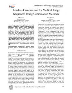
The output of a two-dimensional DCT is a set of N×N coefficients representing the image block data in the DCT domain and these coefficients can be considered as ‘weights’ of a set of standard basis patterns [13]. The basis patterns for an 8×8 DCTs are shown in Figure 1-a and are composed of combinations of horizontal and vertical cosine functions. Any image block may be reconstructed by combining all N×N basis patterns, with each basis multiplied by the appropriate weight.
(1)
Wij = Ci cos
Where Ci =
1 N
2
(i = 0) , C i =
N
(i ≥ 0 )
Another way to present the DCT and the IDCT is as follows equations 2 and 3 respectively: N −1 N −1 ( 2 j + 1 ) yπ ( 2i + 1 ) xπ ∑ B ij cos Z xy = C x C y ∑ cos i =0 j =0 2N 2N
(2)
N −1 N −1 ( 2 j + 1 ) yπ ( 2i + 1 ) xπ ∑ C x C y Z xy cos Bij = ∑ cos x =0 y =0 2N 2N
(3)
The DCT transformation matrix coefficients are image independent; they are always fixed for the same block size, and hence can be pre-computed and stored separately. For example, the values of a 4×4 transformation matrix W will be =
1 2 1
()
cos 0
π 2 8 1 2π cos 2 8 1 3π cos 2 8 cos
1 2 1
()
cos 0
3π 2 8 1 6π cos 2 8 1 9π cos 2 8 cos
1 2 1
()
cos 0
5π 2 8 1 10π cos 2 8 1 15π cos 2 8 cos
cos (0 ) 2 1 7π cos 2 8 1 14π cos 2 8 1 21π cos 2 8
a) DCT transformation frequencies for 8×8 block.
b) A sample of a cut off frequency by ½ for a 4×4 block size.
c) A sample of a cut off frequency by ¼ for a 4×4 block size.
d) The benchmark cameraman image restored without the DC value.
Figure 1. The basis patterns for an 8×8 DCTs.
1
The result of the DCT transformation for a block in the spatial domain is a set of frequencies that are arranged in a zigzag ascending order as shown in Figure 2. The frequency located at f(0,0) is the lowest frequency and is called the DC value. This value represents the general style of the block and is
474
The International Arab Journal of Information Technology, Vol. 9, No. 5, September 2012
considered to be the most important frequency amongst all the other frequencies in the block. The rest of the frequencies range from low to high in a zigzag pattern and are called the AC values. The AC values contain the details of the block which range from general to fine details, as we progress forward in the zigzag order. a) The original image.
Figure 2. Shows the sequence of an 8×8 frequency block, from low to high.
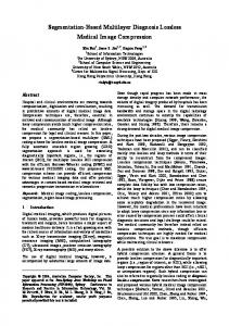
The AC values for each block are not as imperative as the DC value; therefore most of the lossless compression standards that use the DCT neglect a portion of the AC values to save some storage space. Although this results in some distortion when the image is transformed back to the spatial domain, the human visual system will not be able to detect them. Figure 3-b and Figure 3-c show the impact of cuttingoff various portions of the AC values based on the pattern shown in Figure 1-c and Figure 1-b respectively. As can be inferred, cutting-of half of the AC frequencies did not create a noticeable distortion for the human visual system and the observer will still be able to view the fine details in the image. Even when all the AC values are removed and the DC value is maintained alone, the human visual system can still understand the general details in that image as shown in Figure 3-d. Figure 1-d shows the opposite of the operation, when the DC value is removed and the image is restored by means of using the AC values only (neglecting the DC value). It is clear in this image that the fine details are available but the general information in that image has been removed as the dc value is not available. Therefore, considering more coefficients (before calculating the IDCT) produces a progressively more accurate reconstruction of the original block and by the time five coefficients out of 16 ( for a 4×4 block) are included, the reconstructed block reasonably matches the original as shown in Figure 1-b and Figure 1-c. Hence, it is possible to reconstruct an approximate copy of the block from a subset of the 16 DCT coefficients [13]. Finally, removing the coefficients with insignificant magnitudes enables image data to be represented with a reduced number of coefficient values at the expense of some loss of quality.
c) Cut-off frequency (1/2).
b) Cut-off frequency (1/4).
d) The image restored using the dc value only.
Figure 3. The benchmark “cameraman” image.
4. Proposed Algorithms 4.1. Encryption Algorithm The encryption algorithm uses the DCT to transform the target (original) image into the frequency domain, using a 4×4 discrete cosine transform; and for each block in the frequency domain the following steps are applied. The first step involves scattering the DC value. As the DC value is always distinguished amongst the rest of the frequencies, it is important to set this value to an amount that is indistinguishable from the AC values. This can be done using a weighting factor (which can be used as the encryption key in this algorithm). In this research, it was found that dividing the DC value by the amount of (m × n) , where m and n are the block dimensions is satisfactory, this can be accomplished as follows: f(0,0)=f(0,0)/(m×n). The second step involves reversing the sign of each of the frequencies simply by multiplying the frequency block B * by a value of (-1) as follows: B*=B*×-1. The third stage involves T
transposing the block B*= B * ; this will shuffle the frequencies apart from DC value as it is located at f(0,0). In the fourth step, the 4 diagonal values at the block corners are shuffled using the following sequence f(0,0) ⇔ (m,n) and f(0,n) ⇔ (m,0). In the last stage, the inverse discrete cosine transform of the block IDCT −1 ( B * ) is taken. The block frequencies are transformed back to the pixel domain, with the pixel values changed and the image details concealed. The result of the inverse DCT is added to the rest of the blocks to construct the encrypted image blocks.
Lossless Image Cryptography Algorithm Based on Discrete Cosine Transform
4.2. Decryption Algorithm The decryption algorithm starts by transforming the image into the frequency domain, using a 4×4 discrete cosine transform. For each block in the frequency domain, the following steps apply: the first step involves undoing the frequencies shuffle operation at the corners, in order to return the coefficients back to their correct positions by means of swapping the 4 diagonal values at the block using the sequence f(0,0) ⇔ (m,n) and f(0,n) ⇔ (m,0). The second stage involves transposing the frequency block in order to retrieve the correct positions of the frequencies. The third step involves returning the correct sign of each of the coefficients by multiplying the block by the value of (-1). The fourth step, involves retrieving the exact value of the DC coefficient again, by multiplying it with the weighting factor (the encryption key) as follows: f(0,0)=f(0,0)×(m×n). In the last stage, the
inverse discrete cosine transform of the block is calculated. The block frequencies are transformed back to the pixel domain, and the resulting block will be added to the rest of the blocks to re-construct the original image. Using the proposed encryption/decryption algorithm, the decrypted image pixels will have the same values as the original image. This proposed algorithm ensures a lossless encryption/decryption technique. Figure 4 presents the proposed algorithms in a flowchart. The experiments have been conducted using benchmark testing images with various sizes of (256×256, 512×512, and 1024×1024). The chosen benchmark images vary in the amount of the details they have. The following section discusses the experimental results and shows how images can be encrypted and decrypted without any information loss.
DCT Transformation
DC value scattering using a weighting function (Encryption Key)
Reverse the AC coefficients sign
Encrypted pixel Block (N×N)
IDCT Transformation
Shuffle the coefficients at the corners
Transpose the block
Shuffle the coefficients at the corners
Transpose the NxN coefficients block
Reverse the AC coefficients sign
IDCT Transformation
Retrieving the DC value using a weighting function (Decryption Key)
Encoder
Image pixel Block (N×N)
DCT Transformation Decoder
475
Image pixel Block (N×N)
Figure 4. A flowchart of the proposed image encryption and decryption algorithms.
5. Experimental Results and Quality Assessment The proposed encryption and decryption algorithms can be classified as lossless algorithms (original and decoded images are identical). However, other cryptography systems in general produce images that are susceptible to distortion and degradation of quality. Therefore, substantial encryption is achieved at the expense of quality. On the other hand, in order to evaluate and compare the performance of different encryption methods, it is necessary to judge the visual quality of the decrypted images. As for images that target human observers, the judgement on visual quality has to be relevant to the way the human visual system perceives the view-ability of an image. This in turn brings other challenges which lie in the nonlinear behaviour of the human visual system, and the variety of factors that can affect measuring visual quality. This
makes the assessment task difficult and often leads to vague results. There has been limited research in the area of evaluating image enhancement techniques by defining view-ability measures such as the work on [1, 5, 17].
5.1. Subjective Quality Assessment Human’s visual quality assessment is “subjective”. The human beings’ ability to assess the visual quality of an image is influenced by many aspects such as, the level of interaction with the scene, the comfortability of the viewing environment, and the viewer’s state of mind [13]. In order to set a standardised benchmark for subjective visual quality assessment, the International Telecommunications Union (ITU) has proposed a set of test procedures defined in ITU-R Recommendation BT.500-11 [9]. This recommendation sets the guidelines for the subjective assessment test conditions
476
The International Arab Journal of Information Technology, Vol. 9, No. 5, September 2012
such as the viewing distance, the test duration, and the observers’ recruitment. As the proposed algorithms are lossless (which means no loss in the image information), the subjective quality assessment will reveal an identical subjective match between the original and the decrypted images. Therefore, subjective assessment is inadequate. In order to evaluate the proposed algorithms properly, the authors use objective quality assessment, which provide more reliable results, as shown in the next sub-section.
5.2. Objective Quality Assessment The complication of subjective quality assessment, its variability and inconsistency between human observers have made it necessary to use automated quality assessment techniques that are based on mathematical and computational algorithms to measure the accuracy of the perceived images. Most of the recent objective quality assessment techniques are based on computing the quality of an image to the original image. Amongst those techniques are the Mean Squared Error (MSE) and Peak Signal to Noise Ratio (PSNR) [18]: N 2 MSE = ∑ ( x i − y i ) i =0
the algorithms when the first step of the algorithm is neglected (the dc value scattering is not considered, this involves neglecting step 4 in the decryption part). However, as can be seen in this figure, even without scattering the dc value, the encoded image details are partially concealed. This technique can be applied to any application where the marginal details of an image are required. Table 1. The PSNR results, applied using the original, and decrypted images. Various benchmark image are used. Image “Cameraman” “Tree” “Baboon” “Vegetables” Texture1 Texture2 Texture3 Aireal1 Aireal2 Aireal3
Image Size 256×256 256×256 512×512 512×512 512×512 512×512 512×512 1024×1024 1024×1024 1024×1024
Image Details Medium Medium Medium Medium High High High very high very high very high
PSNR INF INF INF INF INF INF INF INF INF INF
(4)
Where N is the number of pixels in the frame, and xi, yi are the number of pixels in the original and compressed frames, respectively. 2
PSNR = 10 log 10 (
L
)
(5)
MSE
Where L is the dynamic range of pixel values (L= 255 for gray-scale images). PSNR and MSE are criticised for not correlating perfectly with perceived (subjective) quality assessment. However, as the original image and the decrypted images are available, PSNR and MSE will define a highly desirable quality measures that can assess the quality of the decrypted images. PSNR is wildly used in digital image processing applications. The PSNR gives a value of infinity (INF) under one condition only; that is when the original image is compared to itself ( in this case the MSE value in the dominator part of the PSNR equation 5 would result in a zero value, and therefore a division by zero occurs). Otherwise if the PSNR result is >30 db, then the human visual system would not be able to differentiate between the original and processed image progressively, even though the processed image quality is less. A PSNR value of