Sep 27, 2017 - where v(t) is the additive noise at the receiver. ... Agrx,v(t, f), and V [n, m]. = ..... Molisch, and R. Calderbank, âOrthogonal time frequency space ...
1
Low-Complexity Iterative Detection for Orthogonal Time Frequency Space Modulation
arXiv:1709.09402v1 [cs.IT] 27 Sep 2017
P. Raviteja, Khoa T. Phan, Qianyu Jin, Yi Hong, and Emanuele Viterbo ECSE Department, Monash University, Clayton, VIC 3800, Australia Email: {raviteja.patchava, khoa.phan, qianyu.jin, yi.hong, emanuele.viterbo}@monash.edu
Abstract—We elaborate on the recently proposed orthogonal time frequency space (OTFS) modulation technique, which provides significant advantages over orthogonal frequency division multiplexing (OFDM) in Doppler channels. We first derive the input–output relation describing OTFS modulation and demodulation (mod/demod) for delay–Doppler channels with arbitrary number of paths, with given delay and Doppler values. We then propose a low-complexity message passing (MP) detection algorithm, which is suitable for large-scale OTFS taking advantage of the inherent channel sparsity. Since the fractional Doppler paths (i.e., not exactly aligned with the Doppler taps) produce the inter Doppler interference (IDI), we adapt the MP detection algorithm to compensate for the effect of IDI in order to further improve performance. Simulations results illustrate the superior performance gains of OTFS over OFDM under various channel conditions. Index Terms—Delay–Doppler channel, OTFS, message passing, time–frequency modulation.
I. I NTRODUCTION Fifth-generation (5G) mobile systems are expected to accommodate an enormous number of emerging wireless applications with high data rate requirements (e.g., real-time video streaming, and online gaming, connected and autonomous vehicles etc.). While the orthogonal frequency division multiplexing (OFDM) modulation scheme currently deployed in fourth-generation (4G) mobile systems achieves high spectral efficiency for time-invariant frequency selective channels, it is not robust to time-varying channels, especially for channels with high Doppler spread (e.g., high-speed railway mobile communications). Hence, new modulation schemes/waveforms that are robust to channel time-variations are being extensively explored. Recently, orthogonal time frequency space (OTFS) modulation was proposed in [1] showing significant advantages over OFDM, in delay–Doppler channels with a number of paths, with given delay and Doppler values. The delay-Doppler domain is an alternative representation of a time-varying channel geometry due to moving objects (e.g. transmitters, receivers, reflectors) in the scene. Leveraging on this representation, the OTFS modulator spreads each information (e.g., QAM) symbol over a set of two dimensional (2D) orthogonal basis functions, which span across the frequency– time resources required to transmit a burst. The basis function set is specifically designed to combat the dynamics of the timevarying multi-path channel. The general framework of OTFS was given in [1] and a coded OTFS system with forward error
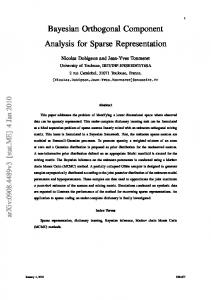
correction (FEC) and turbo equalization was compared with coded OFDM, showing significant gain. In this paper, we analyze the input-output relation describing uncoded OTFS modulation/demodulation for delay–Doppler channels with a number of paths, with given delay and Doppler values. We then propose a low-complexity message passing (MP) detection algorithm, which is suitable for largescale uncoded OTFS taking advantage of the inherent channel sparsity. The MP detection algorithm, based on a sparse factor graph, uses Gaussian approximation of the interference terms to further reduce the complexity, similar to [8] which was applied to massive MIMO detection. Since the fractional Doppler paths (i.e., not exactly aligned with the Doppler taps) produce the inter Doppler interference (IDI), we adapt the MP detection algorithm to compensate for the effect of IDI in order to further improve performance. We show that the proposed MP detection algorithm can also be applied to OFDM systems to compensate for the Doppler effects. Through simulations, we show the superior performance gains of OTFS over OFDM under various channel conditions. II. OTFS MODULATION / DEMODULATION In this section, we describe OTFS modulation/demodulation [1]. A. General OTFS block diagram The OTFS system diagram is given in Fig. 1. OTFS modulation is produced by a cascade of two 2D transforms at both the transmitter and the receiver. The modulator first maps the information symbols x[k, l] in the delay–Doppler domain to symbols X[n, m] in the time–frequency domain using inverse symplectic finite Fourier transform (ISFFT). Next, the Heisenberg transform is applied to time–frequency symbols X[n, m] to create the time domain signal s(t) transmitted over the wireless channel. At the receiver, the received timedomain signal r(t) is mapped to the time–frequency domain through the Wigner transform (the inverse of the Heisenberg transform), and then to the delay–Doppler domain for symbol demodulation. We first introduce the following notation: • The time-frequency plane is discretized by sampling time and frequency axes at intervals T (seconds) and ∆f (Hz), respectively: � Λ = (nT, m∆f ), n = 0, . . . , N −1, m = 0, . . . , M −1 .
2
Time-Frequency Domain x[k, l]
ISFFT
X[n, m] Heisenberg Transform
s(t)
r(t)
Channel h(τ, ν)
Y [n, m] Wigner Transform
SFFT
y[k, l]
Delay-Doppler Domain Fig. 1. OTFS mod/demod
A packet burst has duration N T and occupies a bandwidth M ∆f . • Modulated symbol set X[n, m], n = 0, . . . , N − 1, m = 0, . . . , M − 1 is transmitted over a given packet burst. • Transmit and receive pulses are denoted by gtx (t) and grx (t). Moreover, the delay–Doppler plane is discretized as follows: � n� k o l Γ= , , k = 0, . . . , N −1, l = 0, . . . , M −1 , N T M ∆f •
1 where N1T and M∆f represent the quantization intervals of the Doppler frequency shift and time delay, respectively.
B. OTFS modulation Consider a set of N × M information symbols x[k, l], k = 0, . . . , N − 1, l = 0, . . . , M − 1 from a modulation alphabet A = {a1 , · · · , a|A| } (e.g. QAM), which are arranged on a 2D delay–Doppler grid Γ that we wish to transmit. The OTFS maps x[k, l] to symbols X[n, m] in the time– frequency domain using inverse symplectic finite Fourier transform (SFFT) as follows: N −1 M−1 1 X X x[k, l]ej2π X[n, m] = NM k=0 l=0
nk ml N −M
�
(1)
N −1 M−1 X X
X[n, m]gtx (t − nT )ej2πm∆f (t−nT ) .
where v(t) is the additive noise at the receiver.
D. OTFS demodulation 1) Sufficient statistics and channel distortion: The matched filter computes the cross-ambiguity function Agrx ,r (t, f ): Z ′ ∗ ′ Y (t, f ) = Agrx ,r (t, f ) , grx (t − t)r(t′ )e−j2πf (t −t) dt′ . (4) The matched filter output can be obtained by sampling the function Y (t, f ) at t = nT and at f = m∆f : Y [n, m] = Y (t, f )|t=nT,f =m∆f .
(2)
n=0 m=0
Remark 1: The modulation operation in (2) generalizes OFDM which maps information symbols from frequency domain to time domain. If gtx (t) is a rectangle waveform with duration of T then (2) reduces to conventional inverse discrete Fourier transform. When N = 1, the inner box in Fig. 1 is an OFDM system. Therefore, one OTFS symbol (packet burst) can be viewed as a SFFT precoding applied on N consecutive independent OFDM symbols with M subcarriers. C. Wireless transmission and reception The signal s(t) is transmitted over a time-varying channel with complex baseband channel impulse response h(τ, ν), which characterizes the channel response to an impulse with
(5)
The operation of (4) and (5) is called Wigner transform. Remark 2: Wigner transform is a generalization of the OFDM receiver, which maps the received time domain signal to the frequency domain modulated symbols. When grx (t) is rectangle waveform, it corresponds to the discrete Fourier Transform in OFDM. The relationship between the matched filter output Y [n, m] and the transmitter input X[n, m] was established in [1] as: Y [n, m] = H[n, m]X[n, m] + V [n, m]
for n = 0, . . . , N − 1, m = 0, . . . , M − 1. Next, a time–frequency modulator maps X[n, m] on the grid Λ to a transmitted waveform s(t) by s(t) =
delay τ and Doppler ν [2]. The received signal r(t) is given by: Z Z r(t) = h(τ, ν)s(t − τ )ej2πν(t−τ ) dνdτ + v(t) (3)
where V (t, f ) = Agrx ,v (t, f ), and V [n, m] V (t, f )|t=nT,f =m∆f , and Z Z H[n, m] = h(τ, ν)ej2πτ nT e−j2π(ν+m∆f )τ dνdτ
(6) =
given that h(τ, ν) has finite support bounded by (τmax , νmax ), and the pulses gtx (t) and grx (t) are ideal, i.e., they satisfy the condition Agrx ,gtx (t, f ) = 0 for t ∈ (nT − τmax , nT + τmax ), f ∈ (m∆f − νmax , m∆f + νmax ), where τmax , and νmax are the maximum delay and Doppler values among channel paths. The condition on ideal pulses is called the bi-orthogonal property and it does not hold for practical pulses (for example, rectangular pulses). Nonetheless, we assume ideal pulses as in [1], and the practical pulses are discussed in [10]. Next we apply the SFFT on Y [n, m], yielding [1]: � N −1 M−1 ml nk 1 X X y[k, l] = Y [n, m]e−j2π N − M N M n=0 m=0 =
N −1 M−1 �k − n l − m � 1 X X +z[k, l], (7) , x[n, m]hw N M n=0 m=0 N T M ∆f
3
where z[k, l] ∼ CN (0, σ 2 ) is the additive white noise, and hw (·, ·) is a sampled version of the impulse response function: �k − n l − m � = hw (ν ′ , τ ′ )|ν ′ = k−n ,τ ′ = l−m , hw NT M ∆f N T M ∆f for hw (ν ′ , τ ′ ) being the circular convolution of the channel response with a windowing function: Z Z hw (ν ′ , τ ′ ) = h(τ, ν)w(ν ′ − ν, τ ′ − τ )e−j2πντ dτ dν, N −1 M−1 X X
w(ν, τ ) =
e−j2π(νcT −τ d∆f ).
c=0 d=0
Here, we assume that the rectangular window is applied on the transmitter and receiver symbols X[n, m] and Y [n, m]. III. OTFS UNDER SPARSE
DELAY–D OPPLER CHANNEL
REPRESENTATION
A. Sparse representation of the delay–Doppler channel A sparse representation of the delay–Doppler channel h(τ, ν) in (3) can be expressed as: h(τ, ν) =
P X
hi δ(τ − τi )δ(ν − νi )
(8)
i=1
where P is the number of reflectors; hi , τi , and νi represent the channel gain, delay, and Doppler shift associated with ith reflector, respectively. Here, we assume that the delays for each reflector are different. We now analyze the received symbols y[k, l] in (7) using the sparse presentation of the delay–Doppler channel h(τ, ν) in (8). Let us consider the expression for hw (ν ′ , τ ′ ) by substituting the delay–Doppler channel in (8), hw (ν ′ , τ ′ ) =
P X
hi e−j2πνi τi w(ν ′ − νi , τ ′ − τi )
i=1
=
P X
hi e−j2πνi τi
=
e−j2π(ν
c=0
i=1
P X
N −1 X
′
−νi )cT
M−1 X
ej2π(τ
′
−τi )d∆f
d=0
h′i G(ν ′ , νi ) F (τ ′ , τi ),
(9)
i=1
P j2π(τ ′ −τi )d∆f , where h′i = hi e−j2πνi τi , F (τ ′ , τi ) = M−1 d=0 e P ′ N −1 ′ −j2π(ν −νi )cT and G(ν , νi ) = c=0 e . l−m Let us first evaluate F (τ ′ , τi ) at τ ′ = M∆f , F
�
l−m , τi M ∆f
�
=
M−1 X d=0
2π
ej M (l−m−αi )d =
ej2π(l−m−αi ) − 1
. 2π ej M (l−m−αi ) − 1 (10)
αi Here, we assume that τi = M∆f , where αi is a positive 1 [4]. integer, as the received signal is sampled at interval M∆f From (10), we see that � ( � M, if [l − m − αi ]M = 0 l−m F , , τi = M ∆f 0, otherwise
where mod M operation. Hence, the function � [·]M represents � l−m F M∆f , τi evaluates to M only if m = [l − αi ]M , and m ∈ {0, · · · , M − 1}. Similarly, we have � � ej2π(k−n−βi −γi ) − 1 k−n , νi = j 2π (k−n−β −γ ) G . (11) i i NT e N −1 i +γi ) Here, we assume νi = (βN T , with an integer βi and 0 < γi < 1 (i.e., Doppler frequencies are not necessarily at the sampling points in the delay-Doppler plane). Specifically, αi and βi represents the indexes of the delay tap and Doppler frequency tap, corresponding to delay τi and Doppler frequency νi , respectively. The negative indexes of the Doppler frequency taps, where βi < 0, can also be view as those of positive frequency taps considering mod N operation. We recall that the delay–Doppler channel can be seen as a N × M discretized grid Γ with N and M representing the indexes of the maximum Doppler and delay taps, respectively. We will refer to γi as the fractional Doppler since it represents the fractional shift from a Doppler tap βi in Γ.� The magnitude of the function N1 G k−n N T , νi is � � sin (π ((k − n − βi ) − γi )) 1 k − n G � , νi = π N N sin N NT ((k − n − βi ) − γi )
≥ |sinc (π ((k − n − βi ) − γi ))| . (12)
The above lower bound is tight for small values of π N ((k − n − βi ) − γi ). When γi = 0, the above function has the peak of the main lobe at n = k − βi and the peaks of the side lobes decay at rate of 1/π (k − n − βi ). Therefore, for a given k and βi , the function of γi in (12) has the following properties: 1) Two-sided decreasing function with the peak at n = [k − βi ]N , for 0 < γi ≤ 0.5. 2) Two-sided decreasing function with the peak at n = [k − βi + 1]N , for 0.5 < γi < 1. Therefore, we only consider a� finite number (2Ei + 1) of significant values of G k−n N T , νi in (11) for n = [k − βi + q]N and −Ei ≤ q ≤ Ei , where Ei ≪ N (e.g., Ei = 5 for N = 128). Then we can rewrite the receive signal y[k, l] in (7) as y[k, l] =
Ei P X X
i=1 q=−Ei
h′i
�
ej2π(−q−γi ) − 1 2π
N ej N (−q−γi ) − 1
�
·
x [[k − βi + q]N , [l − αi ]M ] + z[k, l].
(13)
The above input-output expression simplifies for the following special cases. i) Ideal channel – Assuming h(τ, ν) = δ(τ )δ(ν), the received signal becomes y[k, l] = x[k, l] + z[k, l], and behaves as an AWGN channel. ii) No fractional Doppler (γi = 0 for i = 1, . . . , P ) – Assuming that Doppler frequencies are the exact integer
4
2 ) (µde1 ; σde 1
N and M , we consider the symbol-by-symbol MAP detection rule for 0 ≤ c ≤ N M − 1, � � x bc = arg max Pr xc = aj y, H (15)
ye S
ye 1
yd 2 ) (µdeS ; σde S
pceS
pce1 xe S
xe 1
aj ∈A
xc
fe1; e2; · · · ; eS g = Id
fe1; e2; · · · ; eS g = Jc
Observation node messages
Variable node messages
� � 1 Pr y xc = aj , H |A| aj ∈A � � Y Pr ye xc = aj , H . ≈ arg max
= arg max
aj ∈A
Fig. 2. Messages in factor graph
multiples of Doppler taps, the received signal can be obtained by replacing Ei = 0 in (13), i.e., y[k, l] =
P X
h′i x[[k − βi ]N , [l − αi ]M ] + z[k, l].
i=1
For each path, the transmitted signal is circularly shifted by the delay and Doppler taps and scaled by the associated channel gain. From (13), we can see that with the fractional Doppler, the transmitted signal not only shifts by the delay and Doppler taps but also affects the neighboring Doppler taps (−Ei to Ei ). We refer to this interference on the neighboring Doppler taps as inter Doppler interference (IDI). IV. M ESSAGE
PASSING DETECTION ALGORITHM FOR
OTFS We now propose a message passing (MP) detection algorithm for OTFS using the input-output relation in (13). A. Low-complexity MP detection algorithm for OTFS The received signal in vectorized form can be written as y = H x + z,
(14)
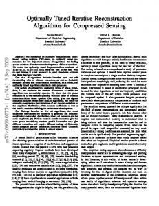
where y ∈ CN M×1 , H = {Hd,c} ∈ CN M×N M , and x ∈ CN M×1 . The (k + N l)-th element of y is yk+N l = y[k, l], for k = 0, · · · , N − 1, l = 0, · · · , M − 1. The elements of x and z are similarly related to x[k, l] and z[k, l], respectively. Due to mod NPand mod M operations in (13), we observe P that only S = i=1 (2Ei + 1) elements out of N M are nonzero in each row and column of H. Let Id and Jc denote the sets of non-zero positions in the dth row and cth column, respectively, then |Id | = |Jc | = S. Based on (14), we model the system as a sparsely connected factor graph with N M variable nodes corresponding to x and N M observation nodes corresponding to y. In this factor graph, the observation node yd is connected to the set of variable nodes {xe , e ∈ Id }. Similarly, the variable node xc is connected to the set of variable nodes {ye , e ∈ Jc }. The joint maximum a posteriori probability (MAP) detection rule for estimating the transmitted information is given by � � b = arg max Pr x y, H , x x∈AN M
which has a complexity exponential in N M . Since the joint MAP detection is intractable even for very small values of
(16)
(17)
e∈Jc
In (17), we assume all the transmitted symbols xc ∈ A are equally likely and the components of y are approximately independent for a given xc , due to the sparsity of H. In order to solve the approximate symbol-by-symbol MAP detection in (17), we propose a MP detector which has a complexity linear in N M . Similarly to [8], for each ye , a variable xc is isolated from the other interference terms, which are then approximated as Gaussian noise with an easily computable mean and variance. In MP, mean and variance of the interference terms are used as messages from observation nodes to variable nodes. The message passed from a variable node xc , for each c = {0, · · · , N M − 1}, to the observation node yd , for d ∈ Jc , is the probability mass function (pmf) pcd = {pcd (aj )|aj ∈ A} of the alphabet symbols in A. Fig. 2 shows the connections and the messages passed between the observation and variable nodes. The MP algorithm operates as follows: (0) Step 1: Initialize iteration index i = 0 and pcd = 1/|A| for c = {0, · · · , N M − 1} and d ∈ Jc . Step 2: Messages are passed from the observation nodes to the variable nodes. The message passed from yd to xc is a Gaussian pdf which can be computed form X (18) yd = xc Hd,c + xe Hd,e + zd , e∈Id ,e6=c
|
{z
}
ζdc
where the interference-plus-noise term ζdc is approximated as Gaussian random variable with mean (i)
µdc = E [ζdc ] =
X
|A| X
(i)
ped (aj )aj Hd,e ,
(19)
e∈Id ,e6=c j=1
and variance (i)
(σdc )2 = Var (ζdc ) (20) 2 |A| |A| X (i) X X (i) = ped (aj )|aj |2 |Hd,e |2 − ped (aj )aj Hd,e +σ 2 . j=1 e∈Id ,e6=c j=1
Further, we assume that transmitted symbols are i.i.d. and independent from the noise. Step 3: Messages are passed from variable nodes to the observation nodes. The new message from xc to yd contains (i+1) the pmf vector pcd with elements (i+1)
pcd
(i)
(i−1)
(aj ) = ∆ · pcd (aj ) + (1 − ∆) · pcd
(aj ),
(21)
5
where ∆ ∈ (0, 1] is the damping factor ( [7]) to improve the convergence rate, and � � Y (i) pcd (aj ) ∝ Pr ye xc = aj , H , e∈Jc ,e6=d
where
2 (i) � � − ye − µec − He,c aj Pr ye xc = aj , H ∝ exp 2,(i) σec
Note that this excludes the information of yd . Step 4: Repeat Step 2 and Step 3 until (i+1) (i) max pcd (aj ) − pcd (aj ) < ǫ c,d,aj
or a maximum number of iterations is reached. Step 5: The final decisions about the transmitted symbols are obtained as x bc = arg max pc (aj ), c ∈ {0, · · · , N M − 1} aj ∈A
where
pc (aj ) =
Y
e∈Jc
� � Pr ye xc = aj , H .
Complexity: The complexity of one iteration involves the computation of (19) and (20), where each computation has a complexity of the order O(N M S|A|). Therefore, the overall complexity per symbol is O(niter S|A|), where niter is the number of iterations. In simulations, we observed that the algorithm converges typically within 20 iterations. We conclude that the sparsity of the delay-Doppler channel representation is a key factor in reducing the complexity of the decoder. The memory requirement is dominated by the storage of (i) (i−1) 2N M S|A| real values for pcd and pcd . In addition, we 2 have the massages (µdc , σdc ), requiring N M S complex values and N M S real values, respectively. B. Application of MP detection algorithm for OFDM over delay–Doppler channels We now apply the above MP algorithm to OFDM to compensate the Doppler effects. The OFDM system can be illustrated by the inner dashed box in Fig. 1, i.e., the Time-Frequency domain. Specifically, the Heisenberg Transform module is replaced by IFFT, cyclic prefix (CP) addition, serial-to-parallel and digital-to-analog conversion, and the Wigner Transform module is substituted with analog-to-digital, parallel-to-serial, CP removal and FFT operation. Also, as mentioned in Remark 1, for OFDM systems, N is set to 1. In OFDM, the received signal r(t) and noise v(t) in (3) are T . Then, the frequency-domain signal after FFT sampled at M operation is given by y = WHt WH x + v
(22)
where (·)H denotes Hermitian transpose, W is M -point FFT matrix, and x ∈ AM×1 is the transmitted information OFDM
Parameter Carrier frequency No. of subcarriers (M ) No. of OTFS symbols (N ) Subcarrier spacing Cyclic prefix of OFDM Modulation alphabet UE speed (km/h) Channel estimation
Value 4 GHz 512 128 15 KHz 2.6 µs 4-QAM 30, 120, 500 Ideal
TABLE I S IMULATION PARAMETERS
symbol. The elements of time-domain channel matrix Ht are given as [9] �� � � 2π(q−1)νi τi M Ht [p, q] = hi δ p − q − ej M , p, q = 1, . . . , M. T M Using the frequency-domain channel matrix H ∈ CM×M = WHt WH , we can re-write (22) as: y = Hx + v.
(23)
Since (23) has similar form as (14), the MP previously developed for OTFS can also be applied for OFDM symbol detection. We note that H is diagonally dominant and the values of off-diagonal elements in each row decay as we move away from the diagonal entry. Hence, the H matrix of OFDM is also sparse, which enables the use of the proposed low complexity MP detection algorithm. Remark 3: From (13) and (22), we can observe the effects of channel gain on the transmitted symbols are different in OTFS and OFDM. In OTFS, all the transmitted symbols experience the same channel gain (independent of k and l), whereas in OFDM, the channel gains are distinct at different subcarriers because of the FFT operation on Ht . V. I LLUSTRATIVE R ESULTS In this section, we simulate the uncoded bit-error-rate (BER) performance of OTFS and OFDM over delay-Doppler channels. All relevant simulation parameters are given in Table I. For both OTFS and OFDM systems, Extended Vehicular A model [3] is applied for the channel delay model, and the Doppler shift of the ith path is generated using νi = νmax cos(θi ), where θi ∼ U(0, π) is uniformly distributed. Fig. 3 shows the BER performance of OTFS system using the proposed MP detector for different number of interference terms (E) with 4-QAM signaling at SNR = 18 dB over the delay-Doppler channel, where UE speed is 120 km/h. Here, we consider Ei = E, ∀i. We can see that there is a significant performance improvement till E = 10 and saturation thereafter, due to the IDI caused by the fractional Doppler. Fewer neighboring interference terms are sufficient to consider in MP (e.g. 5 − 10). In Fig. 4, we illustrate the variation of BER and average number of iterations of OTFS using our MP detector over the delay-Doppler channel, where UE speed is 120km/h. We adopt the damping factor ∆ for E = 10. We consider 4-QAM signaling and SNR = 18 dB. We observe that, when ∆ ≤ 0.7, the BER of MP remains almost the same, but deteriorates
6
100
10 0
OTFS, 30 Kmph OTFS, 120 Kmph OTFS, 500 Kmph OFDM, 30 kmph OFDM, 120 kmph OFDM, 500 kmph
OTFS, 120 Kmph
4-QAM, SNR = 18 dB
10-2
10 -2
10-3
10 -3
10-4
10 -4
10-5
0
5
10
15
10 -5
20
E
100 Average no. of iterations
BER
10-1 10
4-QAM, SNR = 18 dB
10-3 10-4 10-5
0.2
0.4
0.6
∆
0.8
1
10
15
20
25
30
Fig. 5. The BER performance comparison between OTFS and OFDM systems at different Doppler frequencies.
ACKNOWLEDGEMENT
45
OTFS, 120 Kmph
5
SNR in dB
Fig. 3. The BER performance of OTFS for different number of interference terms (E) with 4-QAM.
-2
4-QAM
10 -1
BER
BER
10-1
This research work is support by the Australian Research Council under Discovery Project ARC DP160100528. Simulations were undertaken with the assistance of resources and services from the National Computational Infrastructure (NCI), which is supported by the Australian Government.
OTFS, 120 Kmph
40 35
4-QAM, SNR = 18 dB
30 25 20
R EFERENCES
15 10
0.2
0.4
0.6
0.8
1
∆
Fig. 4. The variation of BER and average no. of iterations with ∆.
thereafter. Further, when ∆ = 0.7, MP converges with the least number of iterations. Hence, we choose ∆ = 0.7 as the optimum damping factor. In Fig. 5, we compare the BER performance of OTFS and OFDM systems using 4-QAM signaling over the delayDoppler channels of different Doppler frequencies (UE speeds of 30, 120, 500km/h). We observe that OTFS outperforms OFDM by approximately 15 dB at BER of 10−4 , thanks to the constant channel gain over all transmitted symbols in OTFS, whereas in OFDM, the error performance is limited by the subcarrier with the lowest gain. Moreover, OTFS exhibits the same performance for different Doppler frequencies thanks to the IDI reduction provided by the MP detector and the assumption on gtx and grx . Similar behavior applies to OFDM, since the inter carrier interference (ICI) can be removed by the MP detector. VI. C ONCLUSION In this paper, we have analyzed the input–output relation describing OTFS mod/demod in terms of sparse representation of the channel in the delay–Doppler domain. In particular, we have introduced the notion of inter Doppler interference caused by the fractional Doppler. We then proposed a linear complexity message passing (MP) detection algorithm which exploits the channel sparsity. Through simulations, we have shown that the effect of IDI can be mitigated by adapting the MP detection algorithm. We have also shown that OTFS has significant BER gains over OFDM under various channel conditions.
[1] R. Hadani, S. Rakib, M. Tsatsanis, A. Monk, A. J. Goldsmith, A. F. Molisch, and R. Calderbank, “Orthogonal time frequency space modulation,” in Proc. IEEE WCNC, San Francisco, CA, USA, March 2017. [2] W.C Jakes, Jr., Microwave Mobile Communications. Wiley, New York, 1974. [3] E. LTE, “Evolved universal terrestrial radio access (E-UTRA); base station (BS) radio transmission and reception (3GPP TS 36.104 version 8.6. 0 release 8), July 2009,” ETSI TS, vol. 136, no. 104, p. V8. [4] D. N. C. Tse, P. Viswanath, Fundamentals of wireless communications. U.K., Cambridge: Cambridge Univ. Press, 2005. [5] O. E. Barbu, C. N. Manchón, C. Rom, and B. H. Fleury, “Message-passing receiver for OFDM systems over highly delay-dispersive channels,” IEEE Trans. Wireless Commun., vol. 16, no. 3, pp. 1564-1578, March 2017. [6] C. W. Huang, P. A. Ting, and C. C. Huang, “A novel message passing based MIMO-OFDM data detector with a progressive parallel ICI canceller,” IEEE Trans. Wireless Commun., vol. 10, no. 4, pp. 1260-1268, April 2011. [7] M. Pretti, “A message passing algorithm with damping,” J. Stat. Mech.: Theory and Experiment, P11008, Nov. 2005. [8] P. Som, T. Datta, N. Srinidhi, A. Chockalingam, and B. S. Rajan, “Low-complexity detection in large-dimension MIMO-ISI channels using graphical models,” IEEE J. Sel. Topics in Signal Processing, vol. 5, no. 8, pp. 1497-1511, December 2011. [9] Y. Zhao, and S. G. Haggman, “Sensitivity to Doppler shift and carrier frequency errors in OFDM systems-the consequences and solutions,” in Proc. 46th IEEE Vehicular Technology Conf., Atlanta, GA, vol. 3, pp. 1564-1568, April 1996. [10] P. Raviteja, K. T. Phan, Q. Jin, Y. Hong, and E. Viterbo, “Interference cancellation for orthogonal time frequency space modulation”, In preparation for submission to the IEEE Trans. Wireless Commun.