Low-loss silicon slot waveguides and couplers fabricated with optical lithography and atomic layer deposition A. Säynätjoki,1,* L. Karvonen,1 T. Alasaarela,1,2 X. Tu,3 T. Y. Liow,3 M. Hiltunen,4 A. Tervonen,1 G. Q. Lo,3 and S. Honkanen1,5 1
Aalto University, School of Electrical Engineering, Tietotie 3, FI-02150 Espoo, Finland 2 Currently at Beneq Oy, Ensimmäinen savu, FI-01510 Vantaa, Finland Institute of Microelectronics, A*STAR (Agency for Science, Technology and Research), 11 Science Park Road, Science Park II, 117685 Singapore 4 VTT, Kaitoväylä 1, 90570 Oulu, Finland 5 University of Eastern Finland, Department of Physics and Mathematics, P.O. Box 111, FI-80101 Joensuu, Finland *
[email protected] 3
Abstract: We demonstrate low-loss silicon slot waveguides patterned with 248 nm deep-UV lithography and filled with atomic layer deposited aluminum oxide. Propagation losses less than 5 dB/cm are achieved with the waveguides. The devices are fabricated using low-temperature CMOS compatible processes. We also demonstrate simple, compact and efficient strip-to-slot waveguide couplers. With a coupler as short as 10 µm, coupling loss is less than 0.15 dB. The low-index and low-nonlinearity filling material allows nonlinearities nearly two orders of magnitude smaller than in silicon waveguides. Therefore, these waveguides are a good candidate for linear photonic devices on the silicon platform, and for distortion-free signal transmission channels between different parts of a silicon all-optical chip. The low-nonlinearity slot waveguides and robust couplers also facilitate a 50-fold local change of the waveguide nonlinearity within the chip by a simple mask design. ©2011 Optical Society of America OCIS codes: (130.3130) Integrated optics materials; (130.4310) Nonlinear; (220.4241) Nanostructure fabrication; (230.7370) Waveguides; (310.2785) Guided wave applications.
References and links 1.
H. Rong, A. Liu, R. Jones, O. Cohen, D. Hak, R. Nicolaescu, A. Fang, and M. Paniccia, “An all-silicon Raman laser,” Nature 433(7023), 292–294 (2005). 2. Y.-H. Kuo, H. Rong, V. Sih, S. Xu, M. Paniccia, and O. Cohen, “Demonstration of wavelength conversion at 40 Gb/s data rate in silicon waveguides,” Opt. Express 14(24), 11721–11726 (2006). 3. R. Salem, M. A. Foster, A. C. Turner, D. F. Geraghty, M. Lipson, and A. L. Gaeta, “All-optical regeneration on a silicon chip,” Opt. Express 15(12), 7802–7809 (2007). 4. Q. Xu and M. Lipson, “All-optical logic based on silicon micro-ring resonators,” Opt. Express 15(3), 924–929 (2007). 5. M. Hochberg and T. Baehr-Jones, “Towards fabless silicon photonics,” Nat. Photonics 4(8), 492–494 (2010). 6. Q. Xu, V. R. Almeida, R. R. Panepucci, and M. Lipson, “Experimental demonstration of guiding and confining light in nanometer-size low-refractive-index material,” Opt. Lett. 29(14), 1626–1628 (2004). 7. T. Baehr-Jones, B. Penkov, J. Huang, P. Sullivan, J. Davies, J. Takayesu, J. Luo, T.-D. Kim, L. Dalton, A. Jen, M. Hochberg, and A. Scherer, “Nonlinear polymer-clad silicon slot waveguide modulator with a half wave voltage of 0.25 V,” Appl. Phys. Lett. 92(16), 163303 (2008). 8. C. Koos, P. Vorreau, T. Vallaitis, P. Dumon, W. Bogaerts, R. Baets, B. Esembeson, I. Biaggio, T. Michinobu, F. Diederich, W. Freude, and J. Leuthold, “All-optical high-speed signal processing with silicon–organic hybrid slot waveguides,” Nat. Photonics 3(4), 216–219 (2009). 9. Y. Yue, L. Zhang, J. Wang, R. G. Beausoleil, and A. E. Willner, “Highly efficient nonlinearity reduction in silicon-on-insulator waveguides using vertical slots,” Opt. Express 18(21), 22061–22066 (2010). 10. T. Baehr-Jones, M. Hochberg, C. Walker, and A. Scherer, “High-Q optical resonators in silicon-on-insulatorbased slot waveguides,” Appl. Phys. Lett. 86(8), 081101 (2005).
#156891 - $15.00 USD
(C) 2011 OSA
Received 20 Oct 2011; revised 25 Nov 2011; accepted 26 Nov 2011; published 8 Dec 2011
19 December 2011 / Vol. 19, No. 27 / OPTICS EXPRESS 26275
11. G. Wang, T. Baehr-Jones, M. Hochberg, and A. Scherer, “Design and fabrication of segmented, slotted waveguides for electro-optic modulation,” Appl. Phys. Lett. 91(14), 143109 (2007). 12. A. Spott, T. Baehr-Jones, R. Ding, Y. Liu, R. Bojko, T. O’Malley, A. Pomerene, C. Hill, W. Reinhardt, and M. Hochberg, “Photolithographically fabricated low-loss asymmetric silicon slot waveguides,” Opt. Express 19(11), 10950–10958 (2011). 13. Z. Wang, N. Zhu, Y. Tang, L. Wosinski, D. Dai, and S. He, “Ultracompact low-loss coupler between strip and slot waveguides,” Opt. Lett. 34(10), 1498–1500 (2009). 14. H. Sun, A. Chen, A. Szep, and L. R. Dalton, “Efficient fiber coupler for vertical silicon slot waveguides,” Opt. Express 17(25), 22571–22577 (2009). 15. T. Alasaarela, D. Korn, L. Alloatti, A. Säynätjoki, A. Tervonen, R. Palmer, J. Leuthold, W. Freude, and S. Honkanen, “Reduced propagation loss in silicon strip and slot waveguides coated by atomic layer deposition,” Opt. Express 19(12), 11529–11538 (2011). 16. A. Säynätjoki, T. Alasaarela, A. Khanna, L. Karvonen, P. Stenberg, M. Kuittinen, A. Tervonen, and S. Honkanen, “Angled sidewalls in silicon slot waveguides: conformal filling and mode properties,” Opt. Express 17(23), 21066–21076 (2009). 17. A. S. Sudbo, “Film mode matching: a versatile numerical method for vector mode field calculations in dielectric waveguides,” Pure Appl. Opt. 2(3), 211–233 (1993). 18. J. Song, H. Zhao, Q. Fang, S. H. Tao, T. Y. Liow, M. B. Yu, G. Q. Lo, and D. L. Kwong, “Effective thermooptical enhanced cross-ring resonator MZI interleavers on SOI,” Opt. Express 16(26), 21476–21482 (2008). 19. F. Grillot, L. Vivien, S. Laval, and E. Cassan, “Propagation loss in single-mode ultrasmall square silicon-oninsulator optical waveguides,” J. Lightwave Technol. 24(2), 891–896 (2006). 20. M. Gehl, R. Gibson, J. Hendrickson, A. Homyk, T. Alasaarela, A. Säynätjoki, A. Tervonen, S. Honkanen, S. Zandbergen, B. C. Richards, J. D. Olitzky, A. Scherer, G. Khitrova, H. M. Gibbs, J.-Y. Kim, and Y.-H. Lee, “Effect of atomic layer deposition on the quality factor of silicon nanobeam cavities,” presented at Fundamental Optical Processes in Semiconductors 2011, August 1–5, 2011, Lake Junaluska, NC, USA.
1. Introduction During the last decade, silicon photonics has gained tremendous interest, and shown many impressive device demonstrations. As a material, silicon has a very high refractive index, enabling microbends and sub-micron light confinement. This makes it possible to realize densely integrated optics, and together with very high χ(3) nonlinearity, even all-optical devices operating at power levels used in telecommunications [1–4]. A significant asset of silicon is that it benefits from the mature processing technology and vast manufacturing infrastructure. To pursue towards low-cost mass production of devices, several projects aiming to silicon foundries have recently been launched [5]. Despite these tremendous prospects, silicon is not the optimal material for every functionality that is needed in e.g. optical telecommunications systems, making it necessary to integrate other materials with silicon waveguides. The high refractive index of silicon makes it challenging to efficiently confine light into any added material. A solution is the slot waveguide which has high optical confinement into a nanoscale low-index slot on silicon [6]. Using the slot waveguide, several improved silicon photonic devices have been demonstrated, such as electro-optic modulators [7] and waveguides with suppressed free-carrier effects and ultrafast nonlinearity [8]. Slot waveguide designs for reduced nonlinearities are proposed to provide distortion-free signal transmission in silicon chips [9]. However, the structure proposed in Ref. 9 is an air slot requiring high aspect ratio processing, which makes fabrication of low-loss waveguides extremely difficult. The fabrication of slot waveguides is challenging, and they typically exhibit relatively high losses. The lowest reported losses are 10 dB/cm for standard slot waveguides [10], and 4 dB/cm for segmented slot waveguides [11], both fabricated with electron beam lithography. Very recently, a loss of 2 dB/cm was reported for asymmetric slot waveguides fabricated with a relatively complicated multi-step lithography process comprising high-temperature oxidation [12]. Also, light coupling into such a nanoscale mode sets challenges. Efficient and compact couplers from a silicon strip waveguide to a slot waveguide [13] and from a fiber to a slot waveguide with help of a polymer waveguide [14] have been presented, but these devices comprise dimensions on the order of 30 nm. In Ref. [13], the strict linewidth demand can be attributed to its ‘Y-branch’ geometry, where the structure has a discontinuity at the center of
#156891 - $15.00 USD
(C) 2011 OSA
Received 20 Oct 2011; revised 25 Nov 2011; accepted 26 Nov 2011; published 8 Dec 2011
19 December 2011 / Vol. 19, No. 27 / OPTICS EXPRESS 26276
the mode field distribution. The needed linewidth is possible with the electron beam lithography, but in order to manufacture the devices in a CMOS line with optical lithography, such dimensions are not currently feasible for waveguides. The reliably manufacturable dimensions are typically limited to about 150 nm. We have shown that thin film growth using the atomic layer deposition (ALD) technique is an efficient method for controlled partial or complete filling of slot waveguides, and that ALD grown materials can exhibit very high optical quality [15,16]. The recent emergence of ALD grown thin films into microelectronics industry directly demonstrates the CMOS compatibility of ALD, making the technique attractive for CMOS photonics. In this paper, we demonstrate low-loss slot waveguides manufactured with 248 nm deepUV lithography and atomic layer deposition, and show by modeling that these slot waveguides exhibit nonlinearity reduction by nearly two orders of magnitude compared to strip waveguides. We also show theoretically and experimentally very simple and compact strip-to-slot waveguide couplers with a very high efficiency even when fabricated with a relatively coarse linewidth. 2. Waveguide and coupler design In slot waveguides, the limitations for the waveguide design arise from the silicon thickness and the linewidth available with the lithography. In this work, we use the most typical silicon thickness, 220 nm. Considering the linewidth limits of the lithography, for waveguides it is extremely important to have a consistent lithography result and, maybe most importantly, smooth sidewalls. For the 248 nm deep UV lithography process used in this work, the linewidths are limited to approx. 200 nm. In the design, we considered rail and slot widths, wr and ws, respectively, between 160 nm and 220 nm. We chose aluminum oxide (Al2O3) with refractive index 1.64 for the slot filling material in this experiment instead of TiO2, which we have earlier found out to be an excellent slot filling material [15]. The nonlinear refractive index n2 of Al2O3 is about 1/200 of that of silicon, which makes it an interesting material for low nonlinearity. Given a solved mode field E,H(x,y) for a structure defined with linear and nonlinear refractive indices n,n2(x,y), the perturbative nonlinear effective index change relative to the propagating power, γ, can be calculated as
1 γ= 2 Z0
∫ n ( x, y ) E ( x, y ) ⋅ n ( x, y ) dA , ∫ Re {E ( x, y ) × H ( x, y )} ⋅ u dA 4
2
2
2
*
(1)
z
where uz is the unit vector in the propagation direction and Z0 is the impedance of free space, 377 Ω. Table 1 shows simulated effective indices and nonlinearities for alumina clad slot waveguides with the dimensions we chose for the experiment. For nonlinear refractive index n2, we used values 4.5*10−18 m2/W for silicon [9], 2.6*10−20 m2/W for silica [9], and 2.8*10−20 m2/W for Al2O3 [16]. For comparison, the single slot waveguide presented in Ref. [9] has γ = 16.61, the more complicated double slot waveguide has a calculated γ = 6.77, and a silicon Table 1. Calculated effective index and γ for silicon slot waveguides covered with 166 nm of Al2O3 wr (nm) 220 20 220 220 200 200 180
#156891 - $15.00 USD
(C) 2011 OSA
ws (nm) 220 200 180 160 200 180 180
neff 1.75 1.76 1.77 1.79 1.69 1.71 1.65
γ (/W/m) 20.77 21.94 23.37 25.16 14.79 16.13 11.70
Received 20 Oct 2011; revised 25 Nov 2011; accepted 26 Nov 2011; published 8 Dec 2011
19 December 2011 / Vol. 19, No. 27 / OPTICS EXPRESS 26277
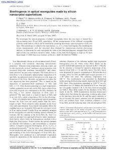
strip waveguide has γ ≈233. The waveguides with dimensions of Table 1 are single mode, except for those with wr = 220 nm and ws>160 nm, which have two guided TE modes. The basic design of the coupler is presented in Fig. 1. Within the coupler length L, the strip waveguide is gradually narrowed down into one of the rails of the slot waveguide. At the same time, the other slot waveguide rail is introduced with an initial width t and linearly expanding to the rail width. The tip width t is limited by the lithography.
Fig. 1. Schematic of the coupler design.
At the tip with a non-zero width, the waveguide geometry has an abrupt transition, causing a potential source of light scattering. This effect could be simply avoided by increasing the separation s between the strip waveguide and the tip. However, in the high-index contrast silicon waveguide, the optical field decays strongly outside the high-index-contrast silicon strip waveguide, and the interaction of the silicon strip waveguide mode with the tip at the distance of 200 nm is small. The modefields of the waveguides and coupling coefficients between modes at the starting point of the coupler were simulated using the FimmWave/FimmProp (Photon Design, Oxford, England), a software based on the film mode matching method [17]. The studied structure consists of a 400 nm wide strip waveguide and a tip with width of 150 nm and a separation of 200 nm. The starting point of the coupler with a 150 nm tip supports the fundamental TE and TM modes which are practically identical to the TE and TM modes in the strip waveguide, and the second-order TE mode that has its effective index of 1.48, i.e., it is very close to the substrate index. The TE modes in the strip waveguide and at the starting point of the coupler are shown in Fig. 2. Intensity coupling from the TE mode of the strip waveguide to the fundamental TE mode at the starting point of the coupler is more than 99.9%, whereas it was less than 2*10−4 to the second-order TE mode in the coupler starting point, and less than 2*10−5 to any of the studied radiating modes (10 first modes in the system were studied).
Fig. 2. Ex field of the guided TE modes in the beginning of the coupler. a) strip waveguide mode, b) fundamental mode in the coupler, c) second-order mode in the coupler.
Light propagation in the coupler was simulated with the BeamProp software (RSoft, Ossining, NY) using the three-dimensional, semivectorial paraxial beam propagation method (BPM). In general, this BPM modeling tool involves some uncertainty for high-index-contrast structures due to approximations made in the algorithm; therefore we regard it as a tool for getting qualitative insight on the light propagation in the structure, rather than giving quantitative data on, e.g., the coupling efficiency of the device. Particularly, we wanted to estimate the length of the coupler for an adiabatic mode conversion as a basis for the coupler design. Figure 3 shows that no significant scattering is observed at the starting point of the #156891 - $15.00 USD
(C) 2011 OSA
Received 20 Oct 2011; revised 25 Nov 2011; accepted 26 Nov 2011; published 8 Dec 2011
19 December 2011 / Vol. 19, No. 27 / OPTICS EXPRESS 26278
coupler. Slight interference between some modes can be seen along the coupler. That may partly be due to the minute coupling to higher order guided or leaky modes in the coupler. Also, some of the initial field in the BPM simulation is not coupled to the guided mode of the waveguide. Some of the interference effects may be due to a small part of this light, reaching the coupler in leaky modes. With BPM simulations, we studied the minimum length of the coupler that ensures smooth mode conversion from the strip-waveguide-like mode to the fundamental mode of the slot waveguide. Figure 3 shows the simulated light propagation in the coupler for different coupler lengths. No significant radiation loss is observed with a taper length down to 10 µm. With shorter couplers, radiation loss is more evident; nevertheless, most of the light remains in the slot waveguide with a coupler as short as 5 µm.
Fig. 3. Simulated light propagation in couplers with different lengths L. Dimensions are given in micrometers. The outline of the structure is highlighted with black lines.
3. Experiment 3.1. Sample fabrication and characterization The slot waveguides were patterned with 248 nm DUV lithography onto 8-inch SOI wafers with a 220 nm thick device layer on 2 µm thick buried oxide. The design contained cutback series for loss characterization with different slot and rail widths, and a separate series of different number of couplers to determine the coupler loss. The silicon was etched in a reactive ion etcher using a Cl2/HBr chemistry. For fiber coupling, inverse tapers were patterned at the end of the waveguide, and the waveguide ends were covered with 2 µm of PECVD SiO2. The coupler was completed using a deep trench etching process which produces smooth vertical facets at the coupling interface [18], and is deep enough to facilitate lateral fiber access, thereby enabling low and repeatable fiber coupling losses from device-todevice. Figure 4 shows a scanning electron micrograph of a fabricated 2-µm long coupler and a waveguide with designed strip and slot width of 200 nm. The fabricated structures had a line width loss of 20 nm from the design width, resulting approximately in 240 nm wide slots and 160 nm wide strips. The tip was designed as rectangular and 150 nm wide, but it is rounded due to the resolution limit of the lithography. The edge quality (line edge roughness) of the lithography is excellent within the resolution of the scanning electron micrograph. The atomic layer deposition was carried out with a Beneq TFS500 reactor, using trimethylaluminum and water as precursors for aluminum and oxygen, respectively. The growth temperature was 200 ºC. The growth of 1500 cycles yielded a film with a thickness of #156891 - $15.00 USD
(C) 2011 OSA
Received 20 Oct 2011; revised 25 Nov 2011; accepted 26 Nov 2011; published 8 Dec 2011
19 December 2011 / Vol. 19, No. 27 / OPTICS EXPRESS 26279
166 nm. As a side product, the 166 nm thick Al2O3 layer also forms an efficient anti-reflection coating on the chip facets, yielding an estimated 1.5 dB reduction in insertion loss.
Fig. 4. Scanning electron micrograph of a fabricated slot waveguide with a 2-micron long strip waveguide coupler. Some oxide hardmask residue is seen on top of the wider regions of the strip waveguide.
The transmission of the waveguides was measured using a superluminescent LED source with a center wavelength of 1530 nm and a bandwidth of 100 nm. With a wide band source, Fabry-Pérot oscillations arising from e.g. chip facets are averaged out. The input of only the TE mode into the chip was ensured with fiber polarizers and polarization maintaining (PM) fibers. The light was coupled into and out from the chip using tapered PM fibers, which provide efficient coupling to the inverse tapers on the chip. The mode size of the tapered fibers was 2 µm, defined as the measured FWHM for fiber-to-fiber coupling. In order to facilitate an optical path to incorporate the required slot waveguide sections, the chips in this work also comprise approximately a 3.4 mm long and 400 nm wide silicon strip insertion waveguide with four 180 degree bends having a bending radius of 25 µm., and four strip-toslot waveguide and slot-to-strip waveguide couplers. Total fiber-to-fiber insertion loss of these chips was typically on the order of 6 dB. 3.2. Propagation loss The loss in the waveguides was measured as a linear regression using data from different waveguides with their lengths ranging from 1 mm to 10 mm. Table 2 shows the propagation loss in the waveguides with different design dimensions. In these waveguides, all strip-to-slot waveguide and slot-to-strip waveguide couplers had a length of 20 µm. Table 2. Measured propagation loss in waveguides wr (nm) ws (nm) Loss (dB/cm) 220 220 5.7±0.3 220 200 5.2±0.3 220 180 4.71±0.05 220 160 5.6±2.0 200 200 6.9±0.8 200 180 8.8±0.8 180 180 15.6*1 1 This waveguide is located at the edge of the chip, and only two different lengths were measurable. Therefore, we were not able to estimate the measurement error.
The lowest loss figures were in the order of 5 dB/cm. This value is among the lowest reported for silicon slot waveguides. To our knowledge, the lowest reported loss for silicon slot waveguides is in the order of 2 dB/cm [10]. However, this loss figure was achieved with a rather complicated multi-mask process, resulting in an asymmetric structure due to an inevitable small misalignment, and therefore a reduced optical confinement in the slot. Also,
#156891 - $15.00 USD
(C) 2011 OSA
Received 20 Oct 2011; revised 25 Nov 2011; accepted 26 Nov 2011; published 8 Dec 2011
19 December 2011 / Vol. 19, No. 27 / OPTICS EXPRESS 26280
the thermal oxidation used in the smoothening of the slot can be a thermal budget issue for some applications. In our work, the waveguides were fabricated at low temperature with a single mask process that yields a high optical confinement in the slot. The waveguide loss, particularly in the case of a slot waveguide, is extremely sensitive to roughness. Therefore, the low loss figure is an indication of a very high patterning quality; the SEM inspection in Fig. 4 showed no roughness, but the low loss is probably even a stronger evidence of an excellent sidewall quality. Other critical factors in waveguide losses are the material loss and, in the case of SOI waveguides, the substrate leakage [19]. The recent improvement of high Q factors in silicon nanobeam cavities [20] is an indication of a very high optical quality of the ALD grown Al2O3, and this study is a further confirmation on that. The refractive index of the Al2O3 coating is also high enough to provide sufficiently high effective index for the waveguide, preventing substrate leakage. The increased loss with the narrowest rails probably arises from substrate leakage. This may be because the rails are narrower than designed, and the effective index of the waveguide is therefore reduced. 3.3. Coupler loss The coupler loss was characterized using structures similar to the previously described length series, but the waveguides in this series had a different number of slot waveguide sections with couplers of varying lengths. The number of slot waveguide sections (i.e., coupler pairs) ranged from 2 to 10. The slot waveguide dimensions used in this study are with the designed wr=ws=200 nm. The measured loss as a function of coupler length is shown in Fig. 5. Loss is in the order of 0.11 dB/coupler for couplers at least 20 µm long. When the coupler length decreases below 10 µm, the loss increases rapidly, as shown in Fig. 5. However, the work shows that our coupler design works well even with compact design and the resolution available with deep UV lithography. The trend in Fig. 5 is also in agreement with our simulations.
Fig. 5. Transmission loss as a function of coupler length for a coupler pair consisting of a stripto-slot waveguide coupler and a slot-to-strip waveguide coupler.
4. Discussion and conclusion In this work, we have presented low-loss slot waveguides made with CMOS compatible lowtemperature processes based on 248 nm deep-UV lithography. We also show that with the same process, very simple, compact and efficient couplers can be realized despite the rather coarse resolution. Placing the non-abrupt tips at a sufficient distance from the input waveguide mode is the key for low-loss couplers with coarse lithography. This is also the first detailed study on the loss of completely ALD filled slot waveguides.
#156891 - $15.00 USD
(C) 2011 OSA
Received 20 Oct 2011; revised 25 Nov 2011; accepted 26 Nov 2011; published 8 Dec 2011
19 December 2011 / Vol. 19, No. 27 / OPTICS EXPRESS 26281
The 248 nm deep-UV lithography limits the slot width to rather large values. With such wide slots, these waveguides have a very low nonlinearity for silicon-based waveguides. Ref. [9] proposed air slot structures for nonlinearity reduction. However, their design with narrow air slot in a thick silicon waveguide is very difficult for fabrication, particularly as it presents mode cutoff very close to the optimal slot width. The waveguides presented in this work have been demonstrated using the common CMOS lithography, and they work despite some offset from the designed dimensions. The nonlinearities and effective indices with the approximate actual dimensions of the characterized waveguides are calculated into Table 3. Due to the rails narrower than designed, the effective nonlinearity of the waveguides is even smaller than for those designed. Table 3. Calculated effective index and γ for the alumina filled slot waveguides with the estimated final geometry wr (nm) 180 180 180 180 160 160 140
ws (nm) 260 240 220 200 240 220 220
neff 1.61 1.62 1.63 1.64 1.57 1.57 1.53
γ (/W/m) 7.43 8.02 8.73 10.52 5.31 5.86 3.22
The disadvantage of the narrower rails is the reduced effective index, which causes substrate leakage loss in the SOI based waveguides [16,18]. This is probably the reason for the increased loss with the narrowest rails. However, most of our waveguides exhibited single-mode operation and very low loss even with some inaccuracies in the linewidth, which shows that our design is very robust. The low loss with such narrow rails is possible only when the slot is completely filled. To our knowledge, this is the first demonstrated slot waveguide that is completely filled with a chemical thin film deposition method. The low loss figure is a further demonstration of the feasibility of ALD in silicon photonics. As such, the waveguides presented here can be used as low-loss, low-nonlinearity waveguides to build passive CMOS photonics with minimal signal distortion. With the presented robust couplers, it is possible to realize photonic circuits with 50x local change in the nonlinearity, simply by the mask design. This makes it possible to make integrated photonic chips with the nonlinearities only at specific locations, while the chip will otherwise maintain the signals without distortion. Acknowledgments The authors thank Dr. J. Hiltunen at VTT and Mr. A. Walden at Aalto University for help in characterization of the waveguides. The work is partially financed by the Finnish Academy grants 134087 (A. S.), 137331 (M. H.) and 128826, Finland-Singapore collaboration funded by Tekes and A*STAR, the Graduate School on Modern Optics and Photonics (L. K. and T. A.) and the Walter Ahlström foundation (L. K.).
#156891 - $15.00 USD
(C) 2011 OSA
Received 20 Oct 2011; revised 25 Nov 2011; accepted 26 Nov 2011; published 8 Dec 2011
19 December 2011 / Vol. 19, No. 27 / OPTICS EXPRESS 26282