IEEE ANTENNAS AND WIRELESS PROPAGATION LETTERS, VOL. 12, 2013
43
Low-Profile Substrate-Integrated Lens Antenna Using Metamaterials Abdallah Dhouibi, Shah Nawaz Burokur, André de Lustrac, Member, IEEE, and Alain Priou, Senior Member, IEEE
Abstract—A low-profile substrate-integrated lens antenna is designed using planar metamaterials for a broadband operation. The lens antenna is based on embedding a Vivaldi antenna source inside a parallel-plate waveguide to illuminate a half Maxwell fish-eye (HMFE) lens operating in X-band. The focusing condition of the lens, requiring a gradient refractive index is achieved through the use of complementary nonresonant metamaterial structures. Numerical simulations are performed to determine the suitable unit cells geometry with respect to the wave launcher inserted into the parallel-plate waveguide. The electric field distribution inside the antenna system has also been explored numerically. Far-field radiation patterns have been measured on a fabricated prototype in an anechoic chamber. It has been shown from both near- and far-field plots that the proposed planar antenna presents good focusing properties. Index Terms—Gradient index materials, lens antenna, parallelplate waveguide, substrate-integrated.
I. INTRODUCTION
M
ETAMATERIALS are artificial materials typically fabricated via suitable periodic arrangement of microstructured metallic or dielectric inclusions. Due to their unusual electromagnetic properties, these microstructured metamaterials have made relevant a wide array of interesting applications. Devices such as invisibility cloaks [1], directive [2] and omnidirectional [3] antennas, Luneburg [4] and Eaton [5] lenses, and waveguide tapers [6] have then been proposed. These devices are generally implemented using materials presenting permittivity and/or permeability gradients, which can be provided by metamaterial technology. In recent years, gradient index (GRIN) lenses have been proposed as alternatives to conventional dielectric ones, where refractive index is varied throughout the lens instead of relying on the interfaces of the dielectric material to control light flow. Thus, GRIN materials [7] have shown their utility in designing a variety of microwave applications. The attractive performances of lens antennas [8] for radio frequency communications have been highlighted. Like the Luneburg lens [9], [10], the Maxwell Manuscript received October 30, 2012; revised December 06, 2012; accepted December 11, 2012. Date of publication January 01, 2013; date of current version March 12, 2013. This work was supported by the EADS Company Foundation under the METAQOPT project, Contract No. 090-AO09-1006. The work of A. Dhouibi was supported by the EADS Company Foundation under a Ph.D. scholarship. A. Dhouibi and A. Priou are with the LEME, EA 4416, Université Paris Ouest, 92410 Ville d’Avray, France. S. N. Burokur and A. de Lustrac are with the IEF, CNRS, UMR 8622, Université Paris-Sud, 91405 Orsay cedex, France, and also with the Université Paris Ouest, 92410 Ville d’Avray, France (e-mail:
[email protected]). Color versions of one or more of the figures in this letter are available online at http://ieeexplore.ieee.org. Digital Object Identifier 10.1109/LAWP.2012.2237372
fish-eye (MFE) lens [11] is also a spherical GRIN device. The MFE lens is able to focus each point on the lens surface to a diametrically opposite point. A spherical wave at the surface of the lens is converted into a local plane wave at the center of the lens and reemerges as a spherical wave at the surface on the opposite side. In 2006, Fuchs et al. [12] proposed to use only half of the lens, referred to as the half Maxwell fish-eye (HMFE), so as to transform a point source into a plane wave and therefore to produce a highly directive beam. The refractive index of the lens varies from 1 to 2 inside a semicircular geometry and obeys the spatial position function, , where represents the refractive index at the center of the lens, is the radius of the lens, and is the distance from the center of the lens. In this letter, we discuss the design of a substrate-integrated GRIN HMFE lens antenna in which a Vivaldi-type antenna is used as feed. The lens antenna is embedded inside a parallel-plate waveguide. The whole antenna dimensions are 130 190 mm with a total height of 11 mm and operation in a quasi-TEM mode in the [8–12 GHz] frequency band. The gradient index of the HMFE lens is achieved through a two-dimensional array of waveguided units of complementary closed-ring (CCR) resonators. Similar lens antennas have been proposed in a parallel-plate waveguide configuration [13] and through the use of metamaterial-based Luneburg lenses [14], [15]. Compared to Rotman’s parallel-plate microwave lens [16] and the two-dimensional Luneburg lens [17], here we use an integrated planar feed source. The proposed antenna configuration is low-profile and lightweight and presents broadband characteristics. Furthermore, the use of a planar feed in the overall low-profile lens antenna suggests a good matching to the semispherical surface and an easy integration into RF communication systems. II. METAMATERIAL-BASED LENS DESIGN The unit cell of the metamaterial structure considered to create the gradient index consists of a planar CCR resonator patterned in the copper cladding of a 0.4-mm-thick Rogers RT/Duroid 5880 dielectric substrate presenting relative per, and loss tangent, . Such a mittivity, complementary resonator operates in a quasi-TEM waveguide configuration as shown in Fig. 1(a) and exhibits a magnetic resonance when the E-field is aligned perpendicularly to its plane. To obtain the desired effective index of the CCR units, the properties are characterized numerically using Maxwell’s equations solver of CST Microwave Studio Suite. The polarization of the incident TEM wave is constrained by the use of perfect magnetic conducting (PMC) boundaries on the sides of
1536-1225/$31.00 © 2013 IEEE
44
IEEE ANTENNAS AND WIRELESS PROPAGATION LETTERS, VOL. 12, 2013
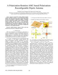
Fig. 2. HMFE lens antenna composed of a planar metamaterial-based lens and a Vivaldi antenna feed placed in a quasi-TEM parallel-plate waveguide. The mm, mm, and . dimensions of the feed are: mm, mm, mm, In the whole antenna system: mm, and mm.
Fig. 1. (a) CCR resonator. (b) Extracted effective index for three different cells. mm, mm, mm, and The inset shows the CCR cell with: and are variable parameters.
the computational domain in the -plane. The gap between the patterned circuit board and the top copper plate of the waveguide is fixed to 1 mm. Radiation boundaries are assigned below the ports in the -plane. The two ports are positioned far away from the resonator structure to avoid near-field cross coupling between the ports and the CCR. However, the phase reference planes for the retrieval are chosen such that the period of the CCR unit cell is kept as 3.6 mm. The broadband metamaterial-based HMFE lens of radius mm is designed for X-band operation. The nonresonant CCR structure is used as the basic unit cell of the lens. Due to the square profile of the CCR structure, the HFME lens is discretized into seven concentric quasi-semicircular regions. The first region corresponds to the cell with mm, while the last one corresponds to mm. Therefore, each region corresponds to a specific refractive index. The electromagnetic parameters are retrieved using the simulated -parameters as proposed by the inversion method described in [18]. Fig. 1(b) shows the real part of the effective index ( ) for three different cell dimensions of the waveguided CCR metamaterials. They are utilized in their nonresonant frequency regime such that they present broadband material properties in the 8–12-GHz band. Indeed for frequencies well below resonance, the unit cell behaves as an effective medium. We can observe that the index present low dispersion except for the case mm since resonance is around 14 GHz for mm. The metamaterial planar slab is inserted in a quasi-TEM waveguide consisting of two parallel copper plates having dimensions mm, mm and spaced by mm. As shown in Fig. 2, the GRIN lens is composed
Fig. 3.
coefficients of the HMFE lens antenna.
of seven regions, each containing two CCR cells. The CCR dimensions and are different in each region in order to provide the gradient index necessary for the HMFE lens. The lens is placed on a Rohacell foam spacer, with a relative permittivity close to 1, to fill up the space between the substrate and the bottom metallic plate. The spacing between the lens and the top metallic plate is set to 1 mm as previously defined by the gap in the simulation of the CCR unit cell. III. FEEDING STRUCTURE DESIGN In order to create a point source on the spherical surface of the lens, a microstrip-fed Vivaldi-type antenna [19] is inserted inside the parallel-plate waveguide. It has been designed to provide an electric field always parallel to the -axis and perpendicular to the CCR plane. The Vivaldi feed is composed of a tapered slot made from the top copper sheet of a 1.6-mm-thick Rogers RT/duroid 5880 dielectric substrate. The slot is excited by a microstrip line printed on the bottom layer of the substrate together with a radial stub, as illustrated in Fig. 2. The feeding circuit of the Vivaldi antenna is composed of the orthogonal transition from the microstrip line to the input slotline of the
DHOUIBI et al.: LOW-PROFILE SUBSTRATE-INTEGRATED LENS ANTENNA USING METAMATERIALS
45
Fig. 4. Simulated near-field distribution of the lens antenna inside the parallel-plate waveguide at different frequencies.
Vivaldi radiating plane. It is a close approximation of a point source that is formed under the slot plane close to the HMFE lens periphery. Nevertheless, placing the feed structure in the parallel-plate waveguide causes parasitic radiations, and TEM waves are formed between the Vivaldi radiating plane and the bottom metallic plate of the waveguide. Such fields are unfavorable for the excitation of the HFME lens since a second undesirable point source can be created. In order to prevent such effects, the Vivaldi antenna is placed upon two layers of Rohacell foam separated by a thin metallic sheet and fixed to the bottom plate of the parallel-plate TEM waveguide. A metallic via is inserted between the slot radiating plane and the metallic sheet separating the two Rohacell layers. The radial stub feeding the Vivaldi antenna is thus shielded between two metallic planes that are short-circuited by the via acting as a stopband filter for TEM waves. Such a configuration allows to avoid having an undesirable point source resulting from the microstrip line and also to ensure low spurious radiation and hence low cross-polarization levels. The metallic via serves also as an extension of the microstrip feed ground plane and helps to improve the matching of the antenna. A semirigid coaxial cable is used to connect the antenna to the measurement instrumentation via an SMA connector. The measured and simulated return losses of the whole HMFE lens antenna are shown in Fig. 3. The proposed structure provides a return loss greater than 10 dB over the X-band frequency range. IV. RESULTS The electric field map probed above the lens inside the planar waveguide is depicted in Fig. 4 for different frequencies. The simulations have been performed using concentric cylinders representing the effective material parameters and not with the CCR designed material. Perfectly matched layer (PML) absorbing boundaries are applied on the three lateral sides between the parallel plates except in the main radiation direction. Fields near the Vivaldi feed are so strong that the field distribution in the other region cannot be displayed clearly. Hence, the field around the feed is not shown in the plots. As illustrated, after passing through the lens, the circular wave fronts are flattened, and the cylindrical waves are transformed into quasi-plane waves. A directive emission is clearly observed for all tested frequencies. To further investigate the directive behavior of the integrated lens antenna, far-field radiation patterns have been measured using a full anechoic chamber. The measured radiations patterns are presented in Fig. 5. A highly directive emission is observed at all tested frequencies in the H-plane. The sidelobes are below 10 dB for the measured data. A slight asymmetry appears in
Fig. 5. Measured copolarization and cross-polarization (a) H-plane. (b) E-plane ( ) and cross polarization ( ).
components.
the sidelobes due to the offset of the microstrip line feeding the Vivaldi antenna. In the E-plane, a wide beam is radiated, resulting in a fan-shape beam of the lens antenna. The cross-polarization components reported in Fig. 5 show levels remaining below 19 dB over the whole [8–12 GHz] frequency band. To clearly illustrate the lens effect on the Vivaldi feed and to validate the performance of such an integrated lens antenna, measurement performed at 10 GHz in the H-plane without the lens in the TEM waveguide is also plotted [solid trace in Fig. 5(a)]. As it can be observed, the lens renders the beam more directive and lowers the level of the parasitic lobes. The directivity of the proposed metamaterial-based lens antenna is depicted in Fig. 6. Compared to that of an ideal aperture having a similar physical surface as the HMFE lens, a lower directivity is observed in our case. However, the overall performances of the low-profile lens antenna suggest that it can be effectively used in communication antennas and sensor applications.
46
IEEE ANTENNAS AND WIRELESS PROPAGATION LETTERS, VOL. 12, 2013
Fig. 6. Simulated directivity (at broadside) of the proposed lens antenna compared to that of an aperture having same physical surface as the HMFE lens.
V. CONCLUSION In this letter, we have presented a low-profile and substrateintegrated planar HMFE lens antenna. The metamaterial-based lens is excited by a Vivaldi source and configured to operate in a quasi-TEM parallel-plate waveguide. The lens antenna has shown a wideband operation from 8 to 12 GHz. The conceived antenna system exhibits a good return loss and can be easily associated with a radio front end due to its low profile. REFERENCES [1] D. Schurig, J. J. Mock, B. J. Justice, S. A. Cummer, J. B. Pendry, A. F. Starr, and D. R. Smith, “Metamaterial electromagnetic cloak at microwave frequencies,” Science, vol. 314, no. 5801, pp. 977–980, Oct. 2006. [2] P.-H. Tichit, S. N. Burokur, D. Germain, and A. de Lustrac, “Design and experimental demonstration of a high-directive emission with transformation optics,” Phys. Rev. B, vol. 83, no. 15, p. 155108, Apr. 2011. [3] P.-H. Tichit, S. N. Burokur, and A. de Lustrac, “Transformation media producing quasi-perfect isotropic emission,” Opt. Express, vol. 19, no. 21, pp. 20551–20556, Oct. 2011.
[4] N. Kundtz and D. R. Smith, “Extreme-angle broadband metamaterial lens,” Nature Mater., vol. 9, no. 2, pp. 129–132, Feb. 2010. [5] Y. G. Ma, C. K. Ong, T. Tyc, and U. Leonhardt, “An omnidirectional retroreflector based on the transmutation of dielectric singularities,” Nature Mater., vol. 8, no. 8, pp. 639–642, Aug. 2009. [6] P.-H. Tichit, S. N. Burokur, and A. de Lustrac, “Waveguide taper engineering using coordinate transformation technology,” Opt. Express, vol. 18, no. 2, pp. 767–772, Jan. 2010. [7] D. R. Smith, J. J. Mock, A. F. Starr, and D. Schurig, “Gradient index metamaterials,” Phys. Rev. E, vol. 71, no. 3, p. 036609, Mar. 2005. [8] T. Driscoll, D. N. Basov, A. F. Starr, P. M. Rye, S. Nemat-Nasser, D. Schurig, and D. R. Smith, “Free-space microwave focusing by a negative-index gradient lens,” Appl. Phys. Lett., vol. 88, no. 8, p. 081101, Feb. 2006. [9] R. K. Luneburg, Mathematical Theory of Optics. Providence, RI: Brown Univ. Press, 1944. [10] C. H. Walter, “Surface-wave luneberg lens antennas,” IRE Trans. Antennas Propag., vol. AP-8, no. 5, pp. 508–515, Sep. 1960. [11] J. C. Maxwell, ““Solutions of problems,” problem no. 2,” Cambridge Dublin Math. J., vol. 8, pp. 188–195, 1854. [12] B. Fuchs, O. Lafond, S. Rondineau, and M. Himdi, “Design and characterization of half Maxwell fish-eye lens antennas in millimeter waves,” IEEE Trans. Microw. Theory Tech., vol. 54, no. 6, pp. 2292–2300, Jun. 2006. [13] C. Pfeiffer and A. Grbic, “A printed, broadband luneburg lens antenna,” IEEE Trans. Antennas Propag., vol. 58, no. 9, pp. 3055–3059, Sep. 2010. [14] S. Maci, G. Minatti, M. Casaletti, and M. Bosiljevac, “Metasurfing: Addressing waves on impenetrable metasurfaces,” IEEE Antennas Wireless Propag. Lett., vol. 10, pp. 1499–1502, 2011. [15] H. Gao, B. Zhang, S. G. Johnson, and G. Barbastathis, “Design of thin-film photonic metamaterial lüneburg lens using analytical approach,” Opt. Express, vol. 20, no. 2, pp. 1617–1628, Jan. 2012. [16] W. Rotman and R. F. Turner, “Wide-angle microwave lens for line source applications,” IEEE Trans. Antennas Propag., vol. AP-11, no. 6, pp. 623–632, Nov. 1963. [17] G. D. M. Peeler and D. H. Archer, “A two-dimensional microwave luneberg lens,” IRE Trans. Antennas Propag., vol. AP-1, no. 1, pp. 12–23, Jul. 1953. [18] D. R. Smith, S. Schultz, P. Markos, and C. M. Soukoulis, “Determination of effective permittivity and permeability of metamaterials from reflection and transmission coefficients,” Phys. Rev. B., vol. 65, no. 19, p. 195104, May 2002. [19] K. S. Yngvesson, D. H. Schaubert, T. L. Korzeniowski, E. L. Kollberg, T. Thungren, and J. F. Johansson, “Endfire tapered slot antennas on dielectric substrates,” IEEE Trans. Antennas Propag., vol. AP-33, no. 12, pp. 1392–1400, Dec. 1985.