Sang-Gug Lee. Information and Communications University. Information and Communications University. 119 Munjiro, Yuseong-gu, Daejeon, South Korea.
Low-Voltage, Low-Power CMOS Operation Transconductance Amplifier with Rail-to-Rail Differential Input Range Trung-Kien Nguyen Information and Communications University 119 Munjiro, Yuseong-gu, Daejeon, South Korea Abstract-This paper presents a new configuration for linear MOS operation transconductance amplifier (OTA) based on a standard 0.25 g CMOS technology. The proposed circuit combines two previously reported linearization techniques: source degeneration using MOS transistor and class AB linearization. Measured results show that the proposed circuit provides rail-to-rail differential input range. Total harmonic distortion of the proposed circuit is -60 dB at 5 MHz for 0.6Vpp differential input voltage while dissipating only 25 gW
from 1.25 V supply.
Sang-Gug Lee Information and Communications University 119 Munjiro, Yuseong-gu, Daejeon, South Korea proposed transconductor is described. The experimental results and discussions are presented in Section III. The proposed transconductor has been fabricated in a standard 0.25 tm CMOS technology, using 1.25 V supply. And then, the conclusion is presented in Section IV.
A.
II. CIRCUIT DESIGN Circuit topologiesfor linear CMOS OTA
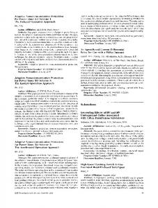
In this section, we will review some linearization techniques that are reported in literature. The simplest technique to linearize the transfer characteristic of the MOS transconductor is the one with source degeneration using resistors as shows in Fig. 1.
I. INTRODUCTION The trend toward lower operating supply voltages and lower power consumption in mixed signal ICs has some strong motivations: 1) portable equipment capable of the v Vdd operating with minimum number of battery cells to reduce volume and weight, 2) voltage limitations resulted from 'outi ,out2 smaller feature sizes of modem IC technology, and 3) longer operating periods without battery recharging or replacement. H The operational transconductance amplifier (OTA) is a Ml M2 Vin+ basic building block in analog circuit applications including vin continuous-time filter, data converter, variable gainnR R amplifiers and other interface circuit [1]-[3]. In many of ss ss these applications, OTA at the input determines the overall voltage linearity of the system [4]. As device sizes, supply and power consumption are scaled down to achieve higher Fig. 1 MOS transconductor with resistive degeneration operating-speeds, obtaining high linearity with reasonable The linearization is achieved because now the output signal levels becomes ever challenging. Several circuit - 'ou2 becomes current lou = techniques have been proposed in literature to improve the ( 1 - tR)2 K (VId linearity of MOS transconductors. The linearization methods 1 include: cross-coupling of multiple differential pairs, [5]-[7], iout = - (J'L I- 0 UR) I ss 2 adapting biasing [8], source degeneration (using resistor or where shift level series connection biasing [11], transistor) [9], [10], 1 W of multiple differential pairs [12], class AB configuration K = 2 [13], and pseudodifferrential stages (using transistors in the L 2 triode region or in saturation) [14], [15]. This paper presents * Vtn and Vid are the threshold voltage of NMOS and an improved linear MOS transconductor that uses both the the differential input voltage respectively. source degeneration using MOS transistor and class AB configuration approaches. Section II reviews these two linearization techniques and the configuration of the newly
0-7803-9390-2/06/$20.00 ©)2006 IEEE
1639
ISCAS 2006
W and L are the width and length of the transistor. are the bias current and degeneration resistor respectively. The transconductance Gm is
*
I,, and R
GC
9.
(2) m where g,m is the transconductance of transistor M1, M2 ( here we assume that MI, M2 are matched) Notice that in (1), the nonlinear term now depends on Vid - oUt R rather than Vid. When R >> 1/gm the non-linear term becomes zero so high linearity can be obtained. The disadvantage of this configuration is the large resistor value, which is needed to achieve a widely linear input range. Since in this case Gm 1/R, the obtained transconductance is restricted by the value of degeneration resistor. If we would like to obtain high transconductance with higher linearity R should be reduced while g. should be increased. High gm requires higher power consumption. Moreover, this technique eliminates the tenability of the Gm is set by the degeneration resistor. The second technique is also using source degeneration but replacing the degeneration resistor with two MOS transistors operating in the triode region that is shown in Fig.2 [9]. Qualitatively, when the amplitude of the input signal rises, the triode-mode degeneration MOS resistors will be more biased such that the synthesized resistance is reduce. This allows less degeneration and results in more Gm of the differential pair to compensate for the drop of Gm. As discussed in [9], the size ratio of M1/M3 = 6.7 is used to obtain the maximally linear behavior. The quantitative relationship is given by 1 + gmR
-
louti ED>-
Vin+
MIl
1
Another topology to achieve highly linear MOS transconductance with low supply voltage is reported in [13]. The idea is to use class AB V-I linearization technique which is shown in Fig. 3. In this topology, the transistors M3, M4, M5, M6 are biased in triode region, therefore the voltage at drain of M1, M2 would be very close to supply voltage and the source voltage can be as low as several tens mV and can be neglected [13]. The transfer function is given by KK(VI-L/)(V1 -2V) - M7 M8 id out 2Kp (Vb - Vt) where Kn, K, Kp are transconductance parameter of NMOSs (M1, M2), (M7, M8), and PMOS (M3, W4), respectively. Vtp is threshold voltage of PMOS. Vd = V,,+ - Vf-,IVb = Vdd -Vb V V + V - 2V and V -V V -V -V As can / 2 s,M7,M8 ' 1 2 - d,M3 d,M4 be seen from (4) that the output current Iout is a function of the differential input voltage Vid. V1 and V2 are very close to Vdd, thus V1+ V2 is almost constant and its nonlinear effect can be ignored. However, with the supply voltage lower than 2 V, the nonlinear term can be occurred [13] Vdd
VbD M
outiV
l
Vin+
lout2 M2
Sl
Mi1i
in-
M5
M6
Mio
M12
Fig. 3 Class AB Transconductor [13]
---cI
Vin-
Fig. 2. Transconductor with source degeneration using MOS transistors [9]
4K1Kn3 (VGSI - Vtn )f (4K +K + Knl)) /Enl (4n3
Mg
Iout2
loM2|
Dt|
(3)
As can be seen in (3), the transconductance can be tuned by changing Iss. However the nonlinearity is up to 1% for 'out I IS . In some filtering application it is required to have
better linearity in order to achieve a total harmonic distortion (TUD) of-60 dB or less [16]
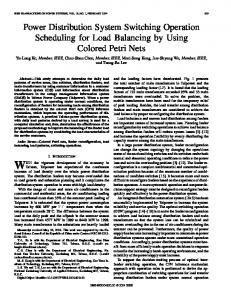
B. Proposed Transconductance Amplifier As discussed in [13], when the supply voltage is reduced below 2V the nonlinear can be increased due to the value of V1 + V2 is not constant. In this design, since we use supply voltage of 1.25V, therefore, the nonlinearity becomes more significant. To resolve this problem, this paper proposes the new transconductor stage configuration that combines the two techniques discussed above: source degeneration using MOS transistor and class AB linearization. The proposed V-I circuit is shown in Fig. 4. In this topology, transistors M3 M8 are operated in triode region. Now, the small-signal drain-source resistance of M7, M8 is given by [17] 1 rdS7 = =(5 rdS8
2K"7(V(; ^- f,)(5
The small-signal source resistance of WI1, WI2 is
1640
r =r =
1
(6)
nKl1 (GS~1 ~n)t
In order to understand how the varying triode transistors help to improve the linearity of this circuit, let us start with a small differential input signal. Qualitatively, assume that if the amplitude of V,n± and Vn is increased, which will reduce the value of V1+ V2 (due to saturation in V1 or V2) therefore the value of V1+ V2 is no longer constant for large input signal. From (4) as discussed before the nonlinear cannot be neglected. To alleviate this reduction for large input signals, the gates of M7 and M8 being connected to the input signals as shown in Fig. 4 can be helpful. Now as the input signal is increased, the small signal resistance of one of the two-triode transistors in parallel, M7 or M8 is reduced based on (5). This reduced resistance tends to boost the value of the V1+ V2 resulting in a partial canceling of the VI+ V2 reduction. Therefore we can conclude that by using two triode transistors M7 and M8, constant current through Ml and M2 will be forced. The constant current through Ml and M2 means the value of V1+ V2 stays constant that will maintain the linearity range. Simulation results show that when the ratio K1IK7 = 5, the proposed topology will give the best linearity. In Fig.4, the V-I characteristic can be tuned by controlling the bias voltage, Vb, of the load transistors, M3, M4. Another advantage of this topology is that it is easily modified to have multiple outputs current by multiplying the size of transistor M13, M14 while it does not affect the V-I conversion process
mio
4
¢
2
0° ° -2
-4 -8 -0.5
-0.3
-0.1
0.1
0.3
0.5
0.7
Fig. 6. The comparison measured V-1 characteristic of OTA in [9], [13] and Vbg. 4. Schematicproposed OTA. |
~~~~~~~~~~~~~~~~-40
Mg
V1
Proposed OTA OTAin[13] OTA in [9]/1-
6
Vin [V]
ltM4
1tM3
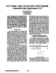
differential current versus the amplitude of the input voltage for three topologies is plotted in Fig. 6. Once can be seen in Fig. 6, the proposed OTA achieves approximately -60 dB at 5 MHz for 0.6-Vpp differential input voltage. The obtained result is lower than other linearization techniques. The measured DC characteristics are shown in Fig. 7. The transconductance plot has been obtained by differentiating the measured output V-I characteristic. From Fig. 7 we can see that the transconductance of proposed OTA almost flattens in the input signal range. The microphotographs of three topologies are shown in Fig. 8. The active sire are of the proposed OTA is 0.1 mm2. 8
-0.7
Vdd
VbD
circuit shows widely linear behavior over the full proposed input voltage range (rail-to-rail) compare to all the other ones. The total harmonic distortion (THD) of the output
-a0
V2
- OTA in [9] asofOTA in [13] Proposed OTA
proposed transconducto5 are f -60
-70
lOSt degneaton cls
B rncndco,
n
h
Fig. 4. Schematic of the proposed OTA III.
RiESULTS AND DisscussioNsVn
0.0
0.1
0.2
0.3
0.4
0.5
0.6
0.7
V
In order to compare the performance of different linearization techniques, three circuits: transconductor using MOS degeneration, class AB transconductor, and the
Fig. 7 The comparison measured THD of OTA in [9], [13], and proposed circuit
with severe linearity requirement. The proposed circuit has good tuning capability and lower THD compared to other approaches. The proposed OTA dissipates only 25 gLW from V supply. ~~~~~~~~~~~~~~1.25
8
4
6
~~~~~~~~~~~~~AcKNOWLEDGMENT
2
0
work was supported by the SRC/ERC program of ~~~~~~~~~~~~~This
~~~~~~~~~~~~~MOST/KOSEF(Intelligent Radio Engineering Center)
0
-6 -8
-0.
-05 -0.7 -. -0.5 -0.3
01 -0.I
01 0.1
03 0.3
05 0.5
Vin [V]
(a) 15 12
-
------------------------------[4] - - .- -~~~~~~~ -..~~~~~
9
REFERENCES [1] V. Gopinathan, et at., " Design consideration and implementation of a ~~~~~~~~~~~~~~~~~programmable high frequency continuous-time filter and variable amplifier in submicrometer CMOS," IEEE Journal of Solid-State vol. 34, pp. 1698-1707, Dec. 1999. 07Circuits, 0.7 [2] P. Real, et al., " A wide-band 10-b 20-Mb/s pipelined ADC using current-mode signals," IEEE Journal of Solid-State Circuits, vol. 26, pp. 11 03 -1109, Aug. 1991 [3] F. Behbahani, et al., " A broad-band tunable CMOS channel-select filter for a low-IF wire- less receiver," IEEE Journal of Solid-State Circuits, vol. 35, pp. 476-489, Apr. 2000 U. Chilakapati, et al., "A CMOS Transconductor with 80-dB SFDR up to 10 MIHlz," IEEE Journal of Solid-Stage Circuits, Vol. 37, No. 3,
~~~~~~~~~~~~~~gain
March 2002
A. Nedungadi, et al., "Design of Linear CMOS Transconductance ~~~~~~~~~~~~~~~[5] IEEE Transactions on Circuits and Systems, vol. CAS-3 1, ~~~~~~~~~~~~~~~~Elements,"
..--
pp. 89 1-894, Oct. 1984. H. Khorramabadi, "High Frequency CMOS Continuos Time Filter," Ph.D. dissertation, Univ. California, Berkeley, 1985. E. Seevinck et al., "A Versatile CMOS Linear Transconductor/Square 3 --Law Function Circuit," IEEE Journal of Solid-State Circuits, vol. SC-22, pp. 366-377, June 1987.
....................[6]
6
~~~~~~~~~~~~~~~~~~[7]
H
[8] M. G. Degrauwe, et al., "Adaptive Biasing CMOS Amplifiers," IEEE Journal of Solid-Stage Circuits, vol. SC-17, pp. 522-528, June 1982. F. Krummenacher, et al. "A 4-MHfz CMOS Continuous-Time Filter ~ ~~~~~~~with On-Chip Automatic Tuning", IEEE Journal of Solid-Stage (b) Circuits, vol. 23, pp. 750-758, June 1988. [10] D. R. Welland, "Transconductance amplifiers and exponential Fig. 8. Measured dc response of the proposed OTA: (a) V-I transfer variable gain using the same," U.S. Patent 5 451 901, Sept. 19, 1995. characteristic, (b) transconductance ....................[11] Z. Wang et al., "A Voltage-Controlled Linear MOS Transconductor .....................Using Bias Offset Technique," IEEE Journal of Solid-Stage Circuits, ......................vol. 25, pp. 315-317, Feb. 1990. 0 -0.7
-0.5
-0.3
-0.1I
0.1 0.3 Vin [V] Vin [V]
0.5
0.7
~ ~ ~[9]
..........[2]J.Slv-Mrtnz,etal, A107-Hz6-d.SR unng"IEE MS ounl oninu f old ............TmeFltr it.ncipAuomtc
.........................[14] R. Minti,netzl,"tunable, Bi1. lz6-BSRCMOS ContinousTieFlrfoHgh IEEEJournaloSli-tg Cicis vol. TimFequien AppictiOns uoatcTnn," S27app 1905-1915, Dec 5 ,De .19 2 7,p. 1992. Cntinous-time FitrApicatons"EecrncsLter s,s-ovo.r25, ufor Degeneratio for
~~andSystems,
LbandADapieBisigng," MideEE Tranosacionson Circuitsan
-Il, Vol. 498,N. 10 p.93-4,O t20.
A new linearMOS transconductor, combining twoAJoni Wiey al.Soun, beBiM SC1997.TmeFltrfrih
linearization..techniques..has.been.presented...The.topology can achieve rail-to-rail linear V-I transfer characteristic and it................................. can be used in implementing fully differential GmC filter.............................Frquny ppictin,"IEE
ouna
f old-taeCicuts vl