Mar 5, 2009 ... Reading for March 12 and 14 – Chapter 15 on wind energy (Note typographical
... Tonight is the first of two lectures on solar energy. It will deal ...
Solar Energy
March 5, 2009
Solar Energy Larry Caretto Mechanical Engineering 496ALT
Alternative Energy March 5, 2009
Homework assignment on nuclear power due tonight. Reading for tonight and next Tuesday – Chapter 13 on solar energy Reading for March 12 and 14 – Chapter 15 on wind energy (Note typographical error for this reading assignment in course outline.)
ME 496ALT Alternative Energy
1
Solar Energy
March 5, 2009
Outline • Solar radiation basics – Angular profiles – Optimum tilt angles – Radiation Intensity – Black body radiation – Solar air mass
• Design of solar collectors – Heat transfer losses – Computing fluid temperatures 2
Tonight is the first of two lectures on solar energy. It will deal mainly with the basics of solar radiation and how those basics are used in the design of solar collectors. We will consider mainly solar thermal collectors tonight and will discuss solar generation of electricity next Tuesday.
ME 496ALT Alternative Energy
2
Solar Energy
March 5, 2009
3
http://www.geog.ucsb.edu/~joel/g110_w07/lecture_notes/sun_angle/agburt0 2_17b.jpg (accessed March 11, 2007) The earth has an elliptic orbit about the sun. The closest earth-sun distance, 147,500,000 km, which is called the perihelion, is reached on January 3. The furthest earth-sun distance, 152,500,000 km, called the aphelion, is reached on July 4. The difference in the earth sun distance between the aphelion and perihelion does not have a significant effect on climate. The difference in seasons is caused by the tilt of the earth. During the northern hemisphere summer the tilt gives more incoming solar radiation to the northern hemisphere and less to the southern. Thus, the southern hemisphere has a winter while the northern hemisphere has summer. At the northern hemisphere summer solstice the sun is pointing directly at the tropic of cancer. At the northern hemisphere winter solstice the sun is pointing directly at the tropic of capricorn. The usual analysis of solar energy takes an earth centered coordinate system which views the sun as in motion about the earth. Copernicus and Galileo may be turning over in their graves about this, but this is really a coordinate transformation to consider a different origin for the relative motion of the sun and the earth. When viewed from the earth, the angle of the sun relative to the earth changes from -23.5 to +23.5 during the year. This angle is known as the declination angle. ME 496ALT Alternative Energy
3
Solar Energy
March 5, 2009
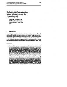
Declination Angle & Relative Earth-Sun Distance
30
Solar Declination Angle
1.02 Declination angle Relative distance
10
1.01
0
1.00
-10
0.99
-20
0.98
-30
Relative Earth-sun Distanc
Declination Angle (degrees
20
1.03
0.97 0
40
80
120
160
200
Julian Date
240
280
320
360 4
This chart was prepared using equations for the declination angle and the relative earth-sun distance accessed on March 11, 2007 at the web site: http://solardat.uoregon.edu/SolarRadiationBasics.html We see that the declination angle goes from -23.5 degrees in at the end of the year to +23.5 degrees in midyear. As noted previously, the earth-sun distance goes from 147,500,000 km on January 3 to 152,500,000 km on July 4. The relative distance between the earth and the sun plotted here is the actual distance divided by the average distance. Of course, the orbit of the earth around the sun actually takes 365.2422 days. The use of leap years makes the empirical formulas only approximate ones. Note that the Gregorian calendar used in the US and Europe today has 365.2425 days per year on average.
ME 496ALT Alternative Energy
4
Solar Energy
March 5, 2009
Solar Angles • Azimuth is daily variation • Declination is annual variation
5
Reference: http://www.homepower.com/files/pvangles.pdf (accessed March 11, 2007) The angles used in defining the location of a solar collector are confusing because they are a combination of two kinds of angles. The first relate to the three- dimensional earth-sun geometry; the second relate to the local planar geometry where a local plane is a tangent to the earth’s surface. The solar declination is the angle that the sun makes with a plane through the equator. In the picture in the lower right the sun will rotate about the North-South (horizontal) coordinate through the year. The solar angle (labeled as θ in this diagram) is more conventionally given the symbol δ, which is used in subsequent slides. The azimuth angle is the angle that the sun makes with the a coordinate system based at a given location. At local solar noon, the sun is due south and the azimuth angle is zero. The azimuth angle is based on the local horizontal plane (horizon). The azimuth angle, z, is different from the hour angle, h, defined on the next slide. The azimuth angle, z, is based on the local horizon, which is a horizontal plane, tangent to the earth’s surface. The hour angle, h, is based on the rotation of the spherical earth.
ME 496ALT Alternative Energy
5
Solar Energy
March 5, 2009
Solar Angles II
6
http://www.srrb.noaa.gov/highlights/sunrise/azelzen.gif accessed March 9, 2007 Here is another view of the azimuth angle. Although this chart shows it being measured clockwise from north, it is generally considered to be zero when the sun is due south. Note that the angles considered here are in a plane at a given location. This plane is tangent to the surface of the earth. These angles are different from angles considered in a spherical coordinate system. This chart also shows the zenith angle, z, and the elevation angle, h, which is later designated as α in these notes and other references. Both these angles are measured with respect to a horizontal plane that is tangent to the surface of the earth at a given location. Note that the elevation angle, h, goes from 0 at sunrise to 0 at sunset.
ME 496ALT Alternative Energy
6
Solar Energy
March 5, 2009
Solar Angles III
from the sun center
7
Reference: Jui Sheng Hsieh, Solar Energy Engineering, Prentice-Hall, 1986. The equatorial plane is a plane that passes through the earth’s equator. A line from the center of the sun to the center of the earth makes an angle, δ, with this plane. This angle is called the declination angle. It varies from 23.47o to –23.47o depending on the time of the year. The declination angle can be approximately computed by the following equation where n is the day of the year (January 1 = 1; December 31 = 365); this is sometimes called the Julian date.
(
)
⎡ 360 (284 + n ) π ⎤⎥ δ = 23.45o sin ⎢ 180 ⎦ ⎣ 365
(δ in degrees )
The latitude, L, at a particular location, P, is the angle with one side on the equatorial plane, its center at the center of the earth, and the other side passing through the location P. The hour angle, h, is a measure of the time of day. It is zero at the local solar noon and advances 150 per hour as the day progresses. With this definition, the hour angle is negative before the local solar noon and is positive after it.
ME 496ALT Alternative Energy
7
Solar Energy
March 5, 2009
Angles for Tilted Collector
8
Reference: Jui Sheng Hsieh, Solar Energy Engineering, Prentice-Hall, 1986. Here the large horizontal plane is tangent to the surface of the earth at a given point. The smaller collector surface is tilted at an angle s from the horizontal plane and an angle ψ from the south (westward direction positive and eastward direction negative.) i is the angle between the normal to the tilted surface and the line of the direct sun rays. This chart also shows the zenith angle, z, and its complement, the altitude angle, α. (α + z = π/2.) These are two ways of measuring the same thing. The zenith angle is the angle between a line from the sun to the position on the earth and a vertical line, normal to the earth at that point. The elevation angle is the angle between a line from the sun to the position on the earth and a plane parallel to the earth at that point. Angle relationships are complex results of solid analytical geometry and trigonometry. The azimuth or altitude angle is given as follows. cos z = sin α = sin L sin δ + cos L cos δ cos h The angle i for a tilted collector is found from the following equation cos i = sin L sin δ cos s – cos L sin δ sin s cos ψ + cos L cos δ cos h cos s + sin L cos δ cos h sin s cos ψ + cos δ sin h sin s sin y Simplifications are possible for a southward facing collector where ψ = 0. Sunrise and sunset occur when the elevation angle, α = 0.
ME 496ALT Alternative Energy
8
Solar Energy
March 5, 2009
Equation of Time
9
Reference for chart: http://freepages.pavilion.net/users/aghelyar/aghpage2.htm The solar time used in the calculation of the hour angle must account for the differences between local time and standard time and certain differences due to the earth and its orbit. The later include the effects of the variable speed of the earth in its elliptic orbit about the sun and the tilt of the earth in its orbit. These two effects are summarized in the equation of time plotted above. An empirical fit to this equation is Equation of Time = 9.87 sin(2B) -7.53 cos(B) – 1.5 sin(B) (minutes) If n is the Julian date, then B (in degrees) is found as follows 360 (n − 81) B= 364 The difference between standard time and local time is accounted for by taking the difference between the standard meridian (120o for Pacific Standard Time, 1050 for Mountain Standard Time, etc.) and the local longitude. The equation is Solar time = Standard time + (4 min per degree)(StandardLongitude – LocalLongitude) + Equation of Time For example, at noon today (March 5; n = 31 + 29 + 5 = 65) the engineering building (Jacaranda Hall – longitude = 118.53o) B = -15.82o, EOT = -12.01 minutes; Standard time = 12:00, longitude adjustment = 4(120 – 118.53 = 5.88 min. Solar time = 12:00 – 9.89 min – 12.01 min = 11:38.10 ME 496ALT Alternative Energy
9
Solar Energy
March 5, 2009
CSUN Engineering Building Sun Path
10
Generated from program located at http://solardat.uoregon.edu/PolarSunChartProgram.html on March 11, 2007. This chart is copyrighted by the University of Oregon Solar Radiation Monitoring Laboratory (SRML) This is the web site for the University of Oregon SRML. At this web page you can input latitude and longitude parameters to plot the chart for any location. The chart shows the path of the sun through the sky by plotting the elevation angle as the angular coordinate in the polar coordinate plot and the elevation angle as the linear coordinate in the plot. Note that the azimuth angle is normally zero at due south. In this plot the coordinates used for the azimuth angle are the normal compass coordinates where south is 180o. Thus the coordinates for the azimuth angle run from 0 to 360 and the elevation angle coordinates run from 0 to 90. Since the sun’s path is symmetric about the summer solstice, the lines for the later half of the year would simply duplicate those for the first half of the year and are not plotted. As an example of reading this chart, the elevation angle on February 20 is 150o when the elevation angle is 40o. This occurs about 10:30 in the morning. Note that the time on this plot is the local standard time. The difference between solar and standard time has been accounted for in the plotting software. The vertical blue lines show the time of day. In May and June, sunrise is as early as 5 am and sunset is as late as 7 pm This plot is done in rectangular coordinates on the next chart. ME 496ALT Alternative Energy
10
Solar Energy
March 5, 2009
11
Generated from program located at http://solardat.uoregon.edu/SunChartProgram.html on March 11, 2007. This chart is copyrighted by the University of Oregon Solar Radiation Monitoring Laboratory (SRML) This is the web site for the University of Oregon SRML. At this web page you can input latitude and longitude parameters to plot the chart for any location. The chart shows the path of the sun through the sky by plotting the elevation angle along the ordinate and the azimuth angle along the abscissa. Note that the azimuth angle is normally zero at due south. In this plot the coordinates used for the azimuth angle are the normal compass coordinates where south is 180o. Thus the coordinates for the azimuth angle run from 0 to 360 and the elevation angle coordinates run from 0 to 80. Since the sun’s path is symmetric about the summer solstice, the lines for the later half of the year would simply duplicate those for the first half of the year and are not plotted. As an example of reading this chart, the azimuth angle on February 20 is 150o when the elevation angle is 40o. This occurs about 10:30 in the morning. Note that the time on this plot is the local standard time. The difference between solar and standard time has been accounted for in the plotting software. The red lines show the time of day. In May and June, sunrise is as early as 5 am and sunset is as late as 7 pm This plot is done in polar coordinates as shown on the previous chart. ME 496ALT Alternative Energy
11
Solar Energy
March 5, 2009
Optimum Fixed Collector Tilt
12
This chart was abridged from the chart in http://www.homepower.com/files/pvangles.pdf To show the use of this chart consider latitude of 35oN. (This is close to the general Los Angeles area. The coordinates for CSUN’s engineering building, Jacaranda Hall, are 34.24oN and 118.53oW.) The day of the year, plotted along the abscissa, starts on the first day of winter. The chart will be symmetric about the first day of summer. The line for this selected latitude starts just below a tilt of about 58o and decreases as the year progresses, reaching a minimum tilt of 120 on the first day of summer. The optimum tilt then increases, symmetric to its decrease, until the first day of winter.
ME 496ALT Alternative Energy
12
Solar Energy
March 5, 2009
Solar Insolation by collector orientation and month at 40oN latitude 13
Reference: http://www.macslab.com/optsolar.html (last accessed March 12, 2007) The graph shows the effect of adjusting the tilt. The blue line is the amount of solar energy you would get each day if the panel is fixed at the winter angle. The red line shows how much you would get by adjusting the tilt four times a year as described below. For comparison, the green line shows the energy you would get from two-axis tracking, which always points the panel directly at the sun. These figures are calculated for 40° latitude. The solar seasons (in the northern hemisphere) for adjusting the tilt are as follows: winter is October 13 to February 27; spring is February 27 to April 20; summer is from April 20 to August 22, and fall is from August 22 to October 13. To calculate the best angle of tilt in the winter, take your latitude, multiply by 0.9, and add 29 degrees.The optimum angle of tilt for the spring and autumn is the latitude minus 2.5°. The optimum angle for summer is 52.5° less than the winter angle. This table gives some examples: Lati- Spring Insolation tude /Fall Angl
% of optimum
Summer Angle
Insolation
25°
22.5
6.5
75%
-1
7.3
75%
30°
27.5
6.4
75%
3.5
7.3
74%
35°
32.5
6.2
76%
8
7.3
73%
40°
37.5
6
76%
12.5
7.3
72%
45°
42.5
5.8
76%
17
7.2
71%
50°
47.5
5.5
76%
21.5
7.1
70%
ME 496ALT Alternative Energy
% of optimum
13
Solar Energy
March 5, 2009
14
Reference: http://www.lbl.gov/MicroWorlds/ALSTool/EMSpec/EMSpec2.html accessed March 11, 2007 This is just a reminder of the various regions of the electromagnetic spectrum ranging from very long to very short. Recall the Planck hypothesis that the energy is proportional to the frequency, E = hν. Thus short wavelength (high frequency) waves have the highest energies. The visible, infrared and ultraviolet portions of the spectrum are shown, in larger scale, on the next slide.
ME 496ALT Alternative Energy
14
Solar Energy
March 5, 2009
15
Reference: http://www.eren.doe.gov/pv/lightsun.html accessed September 2007 The sun emits virtually all of its radiation energy in a spectrum of wavelengths that range from about 2x10⁻⁷ to 4x10⁻⁶ m. The majority of this energy is in the visible region. Each wavelength corresponds to a frequency and an energy; the shorter the wavelength, the higher the frequency and the greater the energy (expressed in eV, or electron volts). Each portion of the solar spectrum is associated with a different level of energy. Within the visible portion of the spectrum, for example, red light is at the low-energy end and violet light is at the high-energy end (having half again as much energy as red light). In the invisible portions of the spectrum, photons in the ultraviolet region, which cause the skin to tan, have more energy than those in the visible region. Likewise, photons in the infrared region, which we feel as heat, have less energy than the photons in the visible region.
ME 496ALT Alternative Energy
15
Solar Energy
March 5, 2009
Black Body Radiation
100,000,000 10,000,000 1,000,000
T = 6000 K T = 5000 K
100,000
T = 4000 K
Radiation 2 W/m -μm 10,000
T = 3000 K T = 2000 K T = 1000 K T = 800 K
1,000
T = 600 K T = 400 K
100
T = 300 K
10 1 0.1
1
10
Wavelength, λ, μm
100
16
The black body is the ideal radiator. Other surfaces radiate energy at some fraction of a black body which is a factor, ε, times the black body radiation. The factor, ε, is called the emissivity. This chart shows that high temperature radiation is located in lower wavelengths around the ultraviolet and visible. The sun can be assumed to be a blackbody radiator with an effective temperature of 10,000oR = 5,555 K. When bodies exchange heat by radiation the radiation that strikes a body can be absorbed, reflected or transmitted. The fraction of incoming radiation that is reflected is called the reflectivity, ρ; the fraction that is absorbed is called the absorbtivity, α; the fraction that is reflected is called the reflectivity, ρ. The sum of these three properties is 1. Solar collectors are typically designed to have a glass plate that will transmit most of the radiation and a solar absorber that with radiation properties that are designed to capture a large fraction of the incoming solar radiation.
ME 496ALT Alternative Energy
16
Solar Energy
March 5, 2009
Black Body Radiation • Spectral Ebλ dλ = ∞
C1
λ5 (eC
2
λT
)
dλ
−1
4 • Integrated Eb = ∫ Ebλ dλ = σT 0
• Radiative heat exchange between two surfaces & 4 4
(
Qrad ,1→2 = A1F12σ T1 − T2
)
• F12 is the shape-emissivity factor
17
The spectral black body equation is the one plotted on the previous page. It shows the radiation in a given wavelength range and is important for understanding the effect of wavelength on radiation. The integrated equation is the one used for basic radiation heat transfer. The constants C1, C2, and σ are defined in terms of fundamental constants and have the values shown below. C1 = 2πhc2 = 3.74177 W·μm4/m2 h = Planck’s constant and c = speed of light in a vacuum C2 = hc/k = 14387.8 μm/K k = Boltzmann’s constant (gas constant per molecule) σ = 2π5k4/(15h3c2) = 5.670x10⁻⁸ W/m2·K4 = 0.1714x10⁻⁸ Btu/hr·ft2·R4 is called the Stefan-Boltzmann constant The shape emissivity factor accounts for the orientation and radiation properties of surfaces exchanging radiation
ME 496ALT Alternative Energy
17
Solar Energy
March 5, 2009
18
Reference: http://www.enter.net/~jbartlo/supp/sungeo.htm (accessed September 2002) The maximum solar energy flux (normal to solar beam) has a slight varation during the year. The maximum is 1422 W/m2 at the earth’s nearest point to sun (perihelion) and 1330 W/m2 at furthest point from sun (aphelion). This is an annual change of 6.7%. The peak solar energy amount (incident to horizontal) at 40°N at the June solstice (summer solstice in northern hemisphere, 1275 W/m2) is less than that at 40°S at the December solstice (summer solstice in the southern hemisphere). However, the minimum energy of 635 W/m2 at 40°N for the northern hemisphere winter solstice is greater than the minium of 585 W/m2 at 40oS during the southern hemisphere summer solstice. The table below shows data on the duration of daytime (DD, hr:min) at various latitudes (LAT, °South) during southern hemisphere summer solstice in December 1995. LAT DD 0 12:06 10 12:41 20 13:19 30 14:03 40 14:59 50 16:19 60 18:47 64 20:51 >= 66 24:00
LAT DD 5 12:23 15 12:59 25 13:40 35 14:29 45 15:34 55 17:19 62 19:38 65 21:47
ME 496ALT Alternative Energy
LAT DD 58 18:06 63 20:11 LAT 65.5 22:29 65.7
DD 22:53
LAT DD 65.9 23:34 18
Solar Energy
March 5, 2009
Solar Irradiance Cycles
19
Reference: http://www.pmodwrc.ch/pmod.php?topic=tsi/composite/SolarConstant accessed March 11, 2007 Until the age of satellites the solar irradiance was thought to be a constant. Satellite measurements during the last 30 years have shown that there is a cycle in the solar irradiance. However the maximum and minima of this cycle are only about one to two percent of the average solar irradiance. For design purposes, solar irradiance may be considered a constant.
ME 496ALT Alternative Energy
19
Solar Energy
March 5, 2009
20
Reference: http://rredc.nrel.gov/solar/pubs/shining/page12_fig.html accessed March 10, 2007 Some of the solar radiation entering the earth's atmosphere is absorbed and scattered. Direct beam radiation comes in a direct line from the sun. Diffuse radiation is scattered out of the direct beam by molecules, aerosols, and clouds. The sum of the direct beam, diffuse, and ground-reflected radiation arriving at the surface is called total or global solar radiation.
ME 496ALT Alternative Energy
20
Solar Energy
March 5, 2009
21
http://rredc.nrel.gov/solar/glossary/gloss_a.html Accessed March 9, 2007 Airmass - the relative path length of the direct solar beam radiance through the atmosphere. When the sun is directly above a sea-level location the path length is defined as airmass 1 (AM 1.0). AM 1.0 is not synonymous with solar noon because the sun is usually not directly overhead at solar noon in most seasons and locations. When the angle of the sun from zenith (directly overhead) increases, the airmass increases approximately by the secant of the zenith angle. A better calculation (Kasten, F. and A. T. Young (1989). Revised optical air mass tables and approximation formula. Applied Optics 28 (22), 4735-4738 ) follows: m = 1.0 / [ cos(Z) + 0.50572 * (96.07995 - Z)1.6364] where Z is the solar zenith angle.
ME 496ALT Alternative Energy
21
Solar Energy
March 5, 2009
22
Reference: http://rredc.nrel.gov/solar/pubs/shining/chap3_sub.html (last accessed March 10, 2007) The elevation of the sun above the horizon, or, conversely, the angle of the sun from the vertical (straight up, or zenith) determines what is called air mass. Air-mass values are higher when the sun is lower in the sky. For example, air mass is 1 when the sun is directly overhead and the angle of the sun from the zenith direction is 0° ;; air mass is 2 when the angle is 60° . The air-mass value at any particular time depends on the location (latitude), the time of day, and the day of the year. When the sun is closer to the horizon, direct beam radiation must pass through a longer distance in the earth's atmosphere than when the sun is overhead. This longer path length results in both more scattering and more absorption of the solar radiation. The atmosphere through which the solar radiation passes is also quite variable. Significant variables are atmospheric turbidity (haziness due to aerosols, such as dust), water vapor, and clouds. So, what exactly is the atmosphere's effect on solar radiation? It basically acts as a dynamic filter, absorbing and scattering solar radiation. It creates spatial (geographic), temporal (hourly, daily), and spectral (wavelength) variations in solar radiation that we must characterize or describe with respect to their effects on operating solar energy conversion systems.
ME 496ALT Alternative Energy
22
Solar Energy
March 5, 2009
Air Mass
23
http://www.udel.edu/igert/pvcdrom/index.html Air mass, AM = 1/cos(θ) ID = direct intensity of sunlight on a plane perpendicular to the sun’s rays in kW/m2 ID = 1.353(0.7)^(AM^0.678) IG = 1.1*ID = global radiation =direct plus diffuse
ME 496ALT Alternative Energy
23
Solar Energy
March 5, 2009
24
Reference: http://rredc.nrel.gov/solar/pubs/shining/page7a_fig.html (last accessed March 9, 2007) Fig. 2: Because of absorption and scattering by the atmosphere, the spectral distribution of solar radiation outside the atmosphere differs significantly from that on earth. Also, the spectral distribution on earth changes throughout the day and year and is influenced by location, climate, and atmospheric conditions. Consequently, the percentage of energy that is composed of UV, visible, or near-infrared radiation, or portions thereof, also varies by location, time of day, and year.
ME 496ALT Alternative Energy
24
Solar Energy
March 5, 2009
July Solar Energy 1983-93
25
Reference: http://asd-www.larc.nasa.gov/ceres/brochure/land_cover.html (last accessed March 12, 2007) While satellites measure radiative flux at the top of the atmosphere, most people are more concerned about conditions on the surface where we live, grow our crops, heat and cool our homes, and enjoy our skiing or beach vacations. Consequently, one of the objectives of the CERES (Clouds and the Earth’s Radiant Energy System) investigation is to better estimate radiative fluxes within the atmosphere and at the surface. CERES surface radiation budget (SRB) data help us understand the trends and patterns of changes in regional land cover, biodiversity, and agricultural production. In particular, CERES can detect variations in surface albedo and longwave emission that signal potential changes in the nature of the land, such as desertification. The SRB provides data on solar energy available at the surface (as shown in the figure below from the Global Energy and Watercycle Experiment SRB project), useful for locating sites for solar power facilities and for architectural design applications.
ME 496ALT Alternative Energy
25
Solar Energy
March 5, 2009
April Insolation 1984-1993
26
http://earthobservatory.nasa.gov/Newsroom/NewImages/images.php3?img_id=480 3 These false-color images show the average solar insolation, or rate of incoming sunlight at the Earth's surface, over the entire globe for the months of January and April. The colors correspond to values (kilowatt hours per square meter per day) measured every day by a variety of Earth-observing satellites and integrated by the International Satellite Cloud Climatology Project (ISCCP). NASA's Surface Meteorology and Solar Energy (SSE) Project compiled these data--collected from July 1983 to June 1993--into a 10-year average for that period. Such images are particularly useful to engineers and entrepreneurs who develop new technologies for converting solar energy into electricity. To attain best results, most devices for harvesting sunlight require an insolation of greater than 3 to 4 kilowatt hours per square meter per day. Luckily, insolation is quite high year round near the equator, where roughly a billion people around the world must spend more money on fuel for cooking than they have to spend on food itself. Natural renewable energy resources is a particularly relevant topic in the United States today as there are rolling blackouts across the state of California while other U.S. city and state governments grapple with energy deregulation issues. To facilitate development of new technologies for harvesting natural renewable energy sources, the SSE Project at NASA's Langley Research Center has made available a wealth of global-scale data on a variety of meteorological topics, including insolation, cloud cover, air temperature, and wind speed and direction. Image courtesy Roberta DiPasquale, Surface Meteorology and Solar Energy Project, NASA Langley Research Center, and the ISCCP Project
ME 496ALT Alternative Energy
26
Solar Energy
March 5, 2009
January Insolation
27
http://earthobservatory.nasa.gov/Newsroom/NewImages/images.php3?img_i d=4803
ME 496ALT Alternative Energy
27
Solar Energy
March 5, 2009
Solar Irradiation by Month in Los Angeles (LAX) Average of Monthly 1961-1990 NREL Data for different collectors 10 9 Fixed, tilt=0 Fixed, tilt=L-15 7
Fixed, tilt=L Fixed,tilt=L+15
2
Irradiation (kWh/m/day)
8
6
Fixed,tilt=90 1-axis,track,EW horizontal
5
1-axis,track,NS horizontal 4
1-axis,track,tilt=L 1axis,tilt=L+15
3
2-axis,track
2 1
Notes: All fixed collectors are facing south The L in tilt = L means the local latitude (33.93oN)
0 Jan
Feb
Mar
Apr
May
Jun
Jul
Aug
Sep
Oct
Nov
Dec
Month
28
Plotted from solar data downloaded from NREL web site for LAX: http://rredc.nrel.gov/solar/old_data/nsrdb/redbook/sum2/23174.txt In addition to the average data given at the web site shown, data are given for each month of data between 1961 and 1990 allowing one to see the variation in year-to-year data. It is possible to obtain equations that allow the direct computation of the solar irradiation, but it is typically better to use actual data that can account for variations in weather and climate.
ME 496ALT Alternative Energy
28
Solar Energy
March 5, 2009
Active Indirect Solar Water Heating
29
Reference: http://www.dnr.mo.gov/energy/renewables/solar6.htm (accessed March 12, 2007) This diagram shows an active, indirect system. It is an indirect system because the where the solar collector fluid is used only as a heat exchange medium to heat the water in the tank; it is not directly used as the hot water supply. It is an active system because it uses an expansion tank to increase pressure. (Pumps are also used in active systems.) The figure shows an backup electric or gas heating element in the tank as well. In direct systems the hot water supply is directly circulated through the solar collector. This can cause problems with freezing during winter operation and indirect systems are preferred in many parts of the world for this reason. In an indirect system the fluid passing through the solar collector usually contains some antifreeze compound such as ethylene glycol to avoid freezing during winter operation.
ME 496ALT Alternative Energy
29
Solar Energy
March 5, 2009
Passive Direct Solar Water Heating
Reference: http://southface.org/solar/solar-roadmap/solar_how-to/batchcollector.jpg (accessed March 12, 2007) This is a passive direct system. It is called a passive system since it does not have a pump. Circulation depends on the density differences between the solar heated water in the collector and the water stored in the tank. It is called a direct system since the water that is ultimate used is the fluid that passes through the solar collector. Such systems are not recommended for regions of freezing temperatures. The only protection against freezing is the ability to drain the collector.
ME 496ALT Alternative Energy
30
Solar Energy
March 5, 2009
Flat Plate Collector
31
http://southface.org/solar/solar-roadmap/solar_how-to/solarhow_solar_works.htm accessed March 12, 2007 In considering the effectiveness of the collector there are two considerations: solar irradiation passes through the glazing and reaches the absorber plate where a certain fraction of it is absorbed. The absorber plate reaches a steady-state temperature that is used to heat the water in the tubes flowing through the absorber plate. Heat is lost by the absorber plate by downward conduction through the insulation and through convection from the glazing. There is also radiative heat loss from the absorber plate.
ME 496ALT Alternative Energy
31
Solar Energy
March 5, 2009
Heat Transfer Analysis & = UA(T • Q loss absorber plate – Tambient) U=
+
1 A' ⎛ T p − Ta ⎞ ⎜ ⎟ T p ⎜⎝ N + B ⎟⎠
0.33
)(
(
+
σ T p + Ta T p2 + Ta2
1 hw
)
⎛ 2N + B −1 ⎞ 1 ⎟− N +⎜ ⎟ ε p + 0.05 N 1 − ε p ⎜⎝ εg ⎠
(
)
• Terminology on notes page 32
Reference: Jui Sheng Hsieh, Solar Energy Engineering, Prentice-Hall, 1986. Definition of terms: & Q loss = heat loss W U = overall heat transfer coefficient W/m2·K A = collector area A’ = 250[1 – 0.0044(s – 90)] B = (1 – 0.04hw + 0.0005hw2)(1 + 0.091N) hw = Wind heat transfer coefficient W/m2·K N = number of glass covers Tp = Mean absorber plate temperature, K Ta = Ambient temperature, K εp = emissivity of absorber plate εg = emissivity of glass s = solar collector tilt angle σ = Stefan Boltzmann constant = 5.670x10⁻⁸ W/m2·K4 This is an empirical expression. Hsieh gives a more detailed procedure for computing the heat transfer for the collector.
ME 496ALT Alternative Energy
32
Solar Energy
March 5, 2009
Heat Transfer Analysis II & = useful heat transfer to working fluid • Q u F'=
1 w⎡ 1 1 1 ⎤ + + U ⎢⎣U (2 LF + D ) C B πDi hi ⎥⎦
[
(
Q& u = AFR H a − U T f ,in − Ta
)]
UAF ' ⎤ ⎡ − m& c p ⎢ m& c p ⎥ FR = 1− e ⎥ UA ⎢ ⎥⎦ ⎢⎣ Q& u T f ,out = T f ,in + m& c p 33
Reference: Jui Sheng Hsieh, Solar Energy Engineering, Prentice-Hall, 1986. Definition of terms: Ha = absorbed solar radiation W/m2 CB = conductance through bond between absorber plate and tubes Di = inside absorber tube diameter hi = inside tube convection coefficient L = half the distance between absorber tubes D = outside diameter of absorber tubes w = 2L + D = separation distance between center of absorber tubes F is the fin efficiency for straight fins with rectangular profile & is the mass flow rate of fluid through the absorber tubes m cp is the heat capacity of the absorber fluid
ME 496ALT Alternative Energy
33
Solar Energy
March 5, 2009
Solar Water Heating Costs • Based on trade association web site • Input: two-person home LA County • Installed cost of recommended system is $3,500 less $1,020 federal tax credit – Area is 3 m2 = 32.3 ft2
• Saves 72 therms/year of natural gas • Savings over expected 15-year life of system are $797 (with 3.8% inflation) 34
Reference http://www.findsolar.com/ accessed March 2, 2008. This is the same web site mentioned last class for the calculation of the costs of photovoltaic electricity. The site also notes an increase in property value of $585 that is not considered here.
ME 496ALT Alternative Energy
34