The Online Journal on Electronics and Electrical Engineering (OJEEE)
Vol. (4) – No. (2)
Mathematical Modeling and Neural Network Control for Dissolved Oxygen of Aquaculture Pond Aeration System Doaa M. Atia1, Faten H. Fahmy1, Ninet M. Ahmed1, and Hassen T. Dorrah2 1
2
Electronics Research Institute,, Cairo, Egypt Faculty of Engineering, Cairo University Email :
[email protected]
Abstract-Dissolved oxygen (DO) is considered as one of the most important aspect of aquaculture. It is needed by fish to respire and perform metabolic activities. Thus low levels of dissolved oxygen are often linked to fish kill incidents. On the other hand, optimum levels can result to good growth, thus result to high production yield. To increase pond production it is necessary to control dissolved oxygen. Artificial intelligence (AI) techniques are becoming useful as alternate approaches to conventional techniques or as components of integrated systems. They have been used to solve complicated practical problems in various areas and are becoming more and more popular nowadays. This paper presents a new design of diffused aeration system using fuel cell as a power source. Mathematical modeling of dissolved oxygen presents in the pond over the day and the fuel cell stack modeling are also presented. Artificial intelligence control techniques are used for controlling the speed of air flow rate from the blower to air piping connected to the pond through control blower speed. MATLAB SIMULINK results show the neural network control (NNC) offer high performance of the system. Keyword: aeration system, fuel cell, artificial intelligence (AI) techniques, neural network control. I. INTRODUCTION Oxygen is the first limiting factor for growth and wellbeing of fish. Fish require oxygen for respiration, which physiologists express as mg of oxygen consumed per kilogram of fish per hour (mg O2/kg/h). Aerators are of two basic types: splashers and bubblers. Splasher type splashes water into the air to affect aeration. Splashing action also causes turbulence in the body of water being aerated. Bubbler aerators rely upon release of air bubbles near the bottom of a water body to affect aeration. A large surface area is created between air bubbles and surrounding water. Rising bubbles also create turbulence within a body of water. Circulation of pond water by aerators is an additional benefit of aeration. NNC and FLC are the two major branches of intelligence control, which is based on the concept of AI. AI can be defined as computer emulation of the human thinking process [1, 2]. In the last years, an interest toward Fuel Cell (FC) studies has grown, as FC is a clean and efficient source of electricity, and has a wide range of transportation and stationary applications. FCs are electrochemical devices that convert the chemical energy of a gaseous fuel directly into
Reference Number: JO-0018
electricity and are widely regarded as a potential alternative stationary power source [3]. They complement heat engines and reduce the dependence on fossil fuels and thus have significant environmental implications. Owing to their attractive characteristics, FCs are recognized as one of the most promising technologies to meet the future power generation requirements and likely to be widely used for the stationary production of electric energy. During the last ten years, there has been a substantial increase in the interest on artificial neural networks. During the last ten years, there has been a substantial increase in the interest on artificial neural networks. Specifically, they are good for tasks involving incomplete data sets, fuzzy or incomplete information and for highly complex and ill-defined problems, where humans usually decide on an intuitional basis [4, 5]. This paper presents the mathematical modeling of fuel cell and dissolved oxygen for aquaculture pond aeration system. Also control of dissolved oxygen of aquaculture pond is achieved using NNC technique. II. DIFFUSED AERATION SYSTEM Diffused-air system aerators use a low pressure, high volume air blower to provide air to diffusers positioned on the pond bottom or suspended in the water. A variety types of diffusers have been used, including ceramic dome diffusers, porous ceramic tubing, porous paper tubing, perforated rubber tubing, perforated plastic pipe, packed columns. Most diffused-air aerators release a large volume of air at low pressure. The minimum permissible system pressure becomes greater with increasing depth of water above diffusers, because enough pressure must be available to force air through the piping system and cause the air to exit from the diffuser against the hydrostatic pressure at the discharge point. Diffused-air systems that release fine bubbles usually are more efficient than those that discharge coarse bubbles. This results because fine bubbles present a greater surface area to the surrounding water than larger bubbles. Oxygen diffuses into water at the surface, so a large surface area facilitates greater oxygen absorption. Diffused-air systems also are more efficient in deep ponds than in shallow ponds. Diffused aeration devices are usually classified as either fine or coarse bubble referring to the relative diameter of the bubble produced. Oxygen can be supplied by means of air or pure oxygen bubbles introduced to the water to create additional gas-water interfaces. Submerged bubbles aeration is most frequently accomplished by dispersing air bubbles in
517
The Online Journal on Electronics and Electrical Engineering (OJEEE)
the liquid. The diffused or bubble aeration process consists of contacting gas bubbles with water for the purpose of transferring gas to the water. The most commonly used diffuser system consists of a matrix of perforated tubes or membranes or porous plates arranged near the bottom of the pond to provide maximum gas to water contact [6, 7].
The proposed aeration system consists of fuel cell stack to provide the system with the required power for operation, controller to control the fuel cell power and blower. Blower feed the system with the required pressure and air flow rate, and finally diffuser connected in the pond bottom as depicted in Fig. 1.
Figure (1): Block diagram of diffused aeration IV. MATHEMATICAL MODELING OF PROPOSED SYSTEM IV.1 Fuel cell mathematical modeling Polymer electrolyte membrane (PEM) fuel cell stacks are being widely considered for many mobile and stationary applications owing to their rapid start-up capability, low operating temperature, modularity in construction, and higher specific energy [8, 9]. Table 1 shows the PEM fuel cell parameters used to validate the model. The total cell potential can be obtained as (1) Vfc = Vn − Vac − Voh − Vcon Where Vn is the reversible voltage, Vac Activation polarization, Voh ohmic losses, and Vcon concentration polarization. Standard potential of the fuel cell with respect to temperature and pressure: 0.5 R ' T p H 2 p O 2 ln p nF H 2O
(2)
Activation polarization is directly related to the rates of electrochemical reactions as: R ' T I fc (3) Vac = ln αnF I o Ohmic losses occur because of resistance to the flow of ions in the electrolyte and resistance to flow of electrons through the electrode materials. the ohmic losses can be expressed by
Voh = R I
(4)
Where I is the current flowing through the cell and R is the total cell resistance, which includes electronic, ionic, and contact resistance. As a reactant is consumed at the electrode by electrochemical reaction, there is a loss of potential due to the inability of the surrounding material to maintain the initial
Reference Number: JO-0018
concentration of the bulk fluid. The concentration polarization is represented by: R ' T I fc (5) Vcon = ln 1 − nF IL Table (1): Parameters used for PEM fuel cell model validation. Symbol Value
III. PROPOSED AERATION SYSTEM
Vn = Vref +
Vol. (4) – No. (2)
Cell temperature T Standard voltage of fuel cell Vr Ideal gas constant R Faraday's constant F Number of electrons transferred in the reaction n Exchange current density Jo Internal resistance Rohm Anode pressure PH2 Cathode pressure pair Limiting current density JL Charge transfer coefficient of reaction
353 K 1.229 V 8.314 J/mol K 96487 C/mol 2 10-4 A/cm2 0.19 Ω/cm2 3 atm 3 atm 1.4 A/cm2 0.239
IV.2 Mathematical Modeling of Blower Motor Blowers and compressors are the dominant sources of energy consumption of a diffused aeration device. Appropriate selection of blowers and compressors can therefore lead to substantial energy and cost savings. From the various types of blowers and compressors manufactured, basically only two groups are applied in aeration system. These include • The positive displacement blower (PD-blower). • The dynamic or centrifugal blower or compressor [10]. For the diffused aeration system, centrifugal blower is used. The electrical system of the blower is DC motor, DC motor drives are used for many speed and position control systems where their excellent performance, ease of control and high efficiency are desirable characteristics. Permanent magnet DC motors are limited in terms of power and control capabilities. A linear model of a simple DC motor consists of a mechanical and electrical equation as determined in the following equations, the operation of the motor is described by [11, 12]:
dI a dt dω m +J dt
Va = E + I a R a + L a Te = TL + B m ω m
P1 N 1 = P 2 N 2
(9) (10)
3
(11)
Where Ra is armature resistance (Ω), La is armature inductance (H), Va is terminal voltage (V), J is moment of inertia (kg m2), B is damping factor of mechanical system (N m s). Ia is armature current (A), TL is load torque (N m), Te is developed torque (N m), and ω is speed of rotation (rpm). N is blower speed (rpm), P blower power (w)
518
The Online Journal on Electronics and Electrical Engineering (OJEEE)
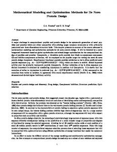
IV.3 The Thermostatic Valve Modeling The required characteristic of this valve must be linear, such that controlling the valve input signal, will directly control the mass flow rate of water. Therefore, the transfer function of the used valve will be considered to be a first order one, as 1 G v (s) = (12) σ s +1 IV.4 Modeling of dissolved oxygen Oxygen in ponds comes from two sources: photosynthesis and diffusion from the air. The most important source, photosynthesis, is the process plants use for manufacturing food. In the presence of sunlight, plants (especially algae) add oxygen to water as a by-product of photosynthesis. At night, no oxygen is produced, but respiration of algae, fish and bacteria continues to remove oxygen from the water. Most of the time there is a desirable balance between how much oxygen is produced and how much is used, but under some conditions, the balance can be upset, and the oxygen concentration becomes low enough to stress or kill fish. The modeling of dissolved oxygen concentration in an aquaculture pond depends upon some factors which contribute oxygen entry into the pond and oxygen removal from the pond. In a pond, dissolved oxygen concentration depends on the balance between photosynthetic productions and total respiration. Figure 2 shows the conceptual model of DO in an aquaculture pond.
Figure (2): Conceptual model of DO dynamics in fish pond. The DO concentration in a pond may be computed from the following equation in which all variables are expressed in milligrams per liter [13]:
DO d = DO i + DO PH − DO FR − DO PR − DO bR
(13)
Where DOd is the DO during the day, DOi is the initial value of DO, DOPH represents DO gained by photosynthesis, DOPR is the DO used for respiration of the planktonic community, DOFR is the DO used in fish respiration, and DObR is the DO used in benthic respiration. The basic equation for predicting night time DO decline is:
DO n = DO dusk − DO FR − DO PR − DO bR DO dusk = DO dawn + ∆DO day
(14) (15)
Where DOday is adjusted daytime DO change. Evaluation of the nighttime DO equation gave highly reliable predictions of early morning DO concentrations.
Vol. (4) – No. (2)
phytoplankton occurs during the night time, where they utilize molecular oxygen present in water to obtain energy as seen in respiration chemical Equation. Other microorganisms present in water also respire and excrete in water which makes further utilization of DO. Respiration by phytoplankton and other microorganisms is a function of temperature as defined by [13]
DO PR = −1.133 + 0.00385 SDD + 0.000014 SDD 2
(16) + 0.081 T − 0.000749 T 2 − 0.00035 SDD T Where SDD is secchi disc depth, T is water temperature oC. 2. Fish respiration Like other living organisms, fish need energy to move, find and digest food, grow, reproduce, in addition to maintaining the body and internal. This energy must be obtained from the environment and then assimilated. Assimilation in fish depends on the use of oxygen to metabolize their food, consequently depleting the DO in water. Total fish respiration rate is represented by [13] (17) Y = 0.001 W 0.82 Where Y is oxygen consumption per fish (gm O2/hr), and W is fish weight (grams). 3. Photosynthetic oxygen production In photosynthesis process, phytoplankton use sunlight energy to synthesize oxygen and carbohydrates for growth. In this process violet light is absorbed by chlorophyll, the energy obtained splits water, and oxygen gas is produced through a reaction. Light is used as a source of energy for the photosynthesis process to produce oxygen. When light penetration is high in the fish pond, photosynthesis takes place over the whole depth of pond, but as time goes on the growth of phytoplankton and increasing turbidity decreases light penetration, making it a limiting factor for phytoplankton growth. The Photosynthetic oxygen production is presented as [1] A p ln (I o I z )C a Pm (18) DO PH = Vp εcCa + ε w
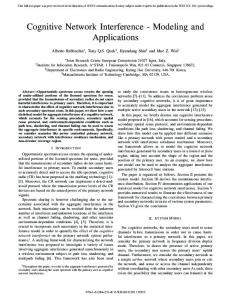
α pIo P m = Popt tanh (19) p opt Where Ap is pond area (m2), Vp pond volume(m3), Io is light intensity at water surface, Iz is light intensity at depth, Ca is chlorophyll a (m2 mg/chl), Pm is specific hourly rate of photosynthesis( mg/chl hr), ε c is specific attenuation of light by chlorophyll a (m2 mg chl/m3), ε w is specific attenuation of light by water (m-1), Popt is optimal specific rate of photosynthesis at saturation light levels and p is slope of the Pm versus Io at low light intensities. Figure 3 shows DO found in the pond over the day and DO percentage required by diffused aeration system. It is clear that DO require in night hours are larger than day hours because the photosynthesis process is presented in the day hours only.
1. Plankton respiration Plankton refers to the group of organisms which float in the surface waters of the rivers, lakes and oceans. Respiration by
Reference Number: JO-0018
519
The Online Journal on Electronics and Electrical Engineering (OJEEE)
8
Where t is target value, and o is output value [14-18].
7
DO in pond
VI. PROPOSED CONTROL TECHNIQUES
DO by aeration 6
DO(mg/Lh)
Vol. (4) – No. (2)
5 4 3 2 1 0 2
4
6
8
10
12
14
16
18
20
22
24
Time (h)
Figure (3): Dissolved oxygen concentration. V. NEURAL NETWORK CONTROL ALGORITHM Neural networks are massively parallel processors that have the ability to learn patterns through a training experience. Traditionally, modeling of equipment and controller algorithms consists of computer programs that rely on complicated mathematics tailored for a specific application, and are generally not portable to other systems. An alternative to traditional models is through the use of neural networks (NN), from a branch of artificial intelligence. Neural networks are nonlinear computer algorithms that can be learned with feedback, and can model the behavior of complicated nonlinear processes. [14-18].
The proposed NN control after many trials eventually employed three layers which are the input layer, hidden layer, and output layer as depicted in Fig. 5. The input layer consists of two neurons, hidden layer consists of three neurons, and output layer of one neurons. The small number of neuron in NNC structure means better in memory and time required for implementation of NNC. NNC is tested and trained using NN toolbox in MATLAB. MATLAB SIMULINK of NNC is depicted in Fig. 6. Figure 7 indicates the weight block diagram of layer1. The training process is carried out over 1000 epochs. The activation function used in this work is "tansig" for hidden layer, and "purelin" for output layer. The NNC is trained using a back propagation with Levenberg– Marquardt algorithm. Figure 8 presents the mean square error between the network output and the target. The network response analysis is depicted in Fig. 9.
Figure (5): Neural network controller architecture.
Figure (4): Single perceptron with a differentiable sigmoidal activation function. V.1 Threshold Logic Unit A simple model of a biological neuron is the so called the threshold logic unit (TLU), shown in Fig. 4. The TLU is also called the perceptron. A TLU is parameterized by a set of weights and a threshold (bias). The summation operation is followed by the sign activation function, V.2 The Error Back-Propagation Algorithm The most popular supervised training algorithm is the one named ‘error back-propagation’, or simply ‘backpropagation’. It involves training a feed forward artificial neural network (FFANN) structure made up of activation function neurons. The back-propagation algorithm is a gradient method aiming to minimize the total operation error of the neural network. The process is intended to minimize the Error between the network output and the output actual output for the same input. The total root mean square error is a function defined by 2 1 RMS = ∑ t j − o j (20) 2 j
Reference Number: JO-0018
Figure (6): Neural network controller.
Figure (7): Block diagram of layer 1 weights. VII. MATLB RESULTS The simulation model of the proposed electrical system of the diffused air aeration system using NN control technique is depicted in Fig. 10. The system consists of the fuel cell subsystem, control subsystem for fuel cell to control the mass flow rate input gases, blower motor subsystem, and finally control subsystem for motor.
520
The Online Journal on Electronics and Electrical Engineering (OJEEE)
Vol. (4) – No. (2)
Figure (8): Mean squareerror error.
Figure (9): Regression between the network output and target. vo
output
To Workspace7
To Workspace12
Scope 9
PFC
pfc To Workspace1
Vc
e
output
input
VFC
Ifc
ifc To Workspace6
Input power Scope 10
Fuel cell Control Subsystem t1
valve
IFC
To Workspace8
fuel cell subsystem
w
.05*u^2 t Clock1
To Workspace5
input 1
To Workspace2
To Workspace9
input
To Workspace11
tl
w
Scope 11 Scope 2 -KInput power 2
va
Gain 1
ia
Scope 1
Scope 4 blower motor subsystem
ia To Workspace4
Scope 3
x{1}
y{1}
output 1 To Workspace3
Neural Network input 2 To Workspace13
Mux
Figure (10): Electrical system of diffused aeration system using NNC.
Reference Number: JO-0018
521
The Online Journal on Electronics and Electrical Engineering (OJEEE)
VIII. RESULTS AND DISCUSSION The results shows, that high performance and accuracy of the proposed system design. Figure 11 shows the variation of blower speed over the day, it is clear that high speed in night and low speed in the day hours. Also blower speed results from the controlled system track reference speed very well. The error signal is represented in Fig. 12, the error signal is very small approximately equal to zero. By applied these results in the system model the required DO from SIMULINK equal to the modeled values. So the controlled subsystem successes in control DO percent in the pond at 6ppm using NNC 1200 Sp e e d R e f sp e e d
S p eed ( r p m )
1000
REFERENCES
600
200
0 0
4
8
12
16
20
24
T im e ( h r )
Figure (11): Blower speed variation with reference signal. 1000 900 800 700 600
E rorr
offers the most immediate and practical solution to water quality problems encountered at higher stocking and feeding rates. Aeration means addition of oxygen to the water. This process is accomplished either by exposing the water to air or by introducing air into the water. In this paper the mathematical modeling of fuel cell and dissolved oxygen for aquaculture pond is suggested and achieved in MATLAB SIMULINK. Moreover, the control of dissolved oxygen of aquaculture pond is achieved using NNC technique. The control system aims to provide the system with required control signal keeping DO in the pond constant at 6 ppm, which is adjusted by controlling blower speed. Three layers NNC with two neurons input layer, three neurons hidden layer, one neuron output layer is developed. The results proved the high accuracy of control subsystem for keeping constant DO percent.
800
400
500 400 300 200 100 0 -1 0 0 0
4
8
12
16
20
24
20
24
T im e (hr)
Figure (12): The error signal. 3 RDO RDOref 2.5
RDO (mg/L h)
Vol. (4) – No. (2)
2
1.5
1
0.5
0 4
8
12
16
Time (hr)
Figure (13): Dissolved oxygen obtained from simulation and required value during the day. IX. CONCLUSION The main goal of the most fish farmers is to maximize production and profits while holding labor and management efforts to the minimum. Risk of fish kills, disease outbreaks, poor water quality In most pond culture operations, aeration
Reference Number: JO-0018
[1] Lopa Ghosh and G.N. Tiwari, "Computer Modeling of Dissolved Oxygen Performance in Greenhouse Fishpond: An Experimental Validation", international journal of agricultural research, Vol. 3, PP. 83-97, 2008. [2] Connie D. DeMoyera, Erica L. Schierholza, John S. Gullivera, Steven C. Wilhelms, "Impact of bubble and free surface oxygen transfer on diffused aeration systems", Water Research , Vol.37, PP. 1890–1904, 2003. [3] Larminie J., Dicks A., “Fuel Cell Systems Explained” John Wiley and Sons, Inc., New York, NY, 2003. [4] Soteris A. Kalogirou "Artificial neural networks in renewable energy systems applications: a review”, Renewable and Sustainable Energy Reviews Vol. 5 pp. 373–401, 2001. [5] D. Driankov, H. Hellendoorn, and M. Reinfrank, ''An introduction to fuzzy control'', Springer-Verlag, Berlin, Heidelberg, 1993. [6] Claude E. Boyd ,”Pond water aeration systems” Aquacultural Engineering Vol.,18 PP., 9–40, 1998. [7] Marcos E. C. Oliveira and Adriana S. Franca, “Analysis of Oxygen Transfer Performance on Sub-surface Aeration Systems”, International Communications Heat and Mass Transfer, Vol., 25, PP., 853-862, 1998. [8] Fuel Cell Handbook, fifth ed., EG&G Services Parsons, Inc., 2000. [9] Colleen Spiegel, "PEM Fuel Cell Modeling and Simulation Using MATLAB", Academic Press, 2008. [10] Energy Efficiency Guide for Industry in Asia – www.energyefficiencyasia.org. [11] Austin Hughes, “Electric Motors and Drives Fundamentals, Types and Applications”, Newnes, 2006. [12] P. Thepsatom, A. Numsomran, V. TipsuwanpoM and T. Teanthong, “DC Motor Speed Control using Fuzzy Logic based on Lab VIEW”, SICE-ICASE International Joint Conference 2006. [13] Claude E. Boyd and Barnaby J. Waffen, "Aeration Systems in Aquaculture", Aquatic Sciences, Vol. 1, PP. 426-472, 1989. [14] Soteris A Kalogiroua, Soa Pantelioub, Argiris Dentsoras, "Artificial neural networks used for the
522
The Online Journal on Electronics and Electrical Engineering (OJEEE)
performance prediction of a thermosiphon solar water heater", Renewable Energy, Vol., 18, PP., 87-99, 1999. [15] James A. Freeman, David M. Skapura, Neural Networks Algorithms, Applications, and Programming Techniques, Addison-Wesley Publishing Company, Inc., Paris, 1991. [16] M.N. Cirstea, A. Dinu, J.G. Khor, M. McCormick, "Neural and Fuzzy Logic Control of Drives and Power Systems", Replika Press Delhi , India, 2002.
Reference Number: JO-0018
Vol. (4) – No. (2)
[17] Soteris A. Kalogirou, "Prediction of flat-plate collector performance parameters using artificial neural networks", Solar Energy, Vol., 80, PP., 248–259, 2006. [18] Adnan Sozen, Tayfun Menlik, Sinan Unvar, "Determination of efficiency of flat-plate solar collectors using neural network approach", Expert Systems with Applications, Vol., 35, PP., 1533–1539, 2008.
523