University of South Carolina
Scholar Commons Faculty Publications
Chemical Engineering, Department of
1-1-1993
Mathematical Modeling of the Formation of Calcareous Deposits on Cathodically Protected Steel in Seawater J. F. Yan University of South Carolina - Columbia
T. V. Nguyen University of South Carolina - Columbia
Ralph E. White University of South Carolina - Columbia,
[email protected]
R. B. Griffin Texas A & M University - College Station
Follow this and additional works at: http://scholarcommons.sc.edu/eche_facpub Part of the Chemical Engineering Commons Publication Info Journal of the Electrochemical Society, 1993, pages 733-744. © The Electrochemical Society, Inc. 1993. All rights reserved. Except as provided under U.S. copyright law, this work may not be reproduced, resold, distributed, or modified without the express permission of The Electrochemical Society (ECS). The archival version of this work was published in the Journal of the Electrochemical Society. http://www.electrochem.org/ Publisher's link: http://dx.doi.org/10.1149/1.2056150 DOI: 10.1149/1.2056150
This Article is brought to you for free and open access by the Chemical Engineering, Department of at Scholar Commons. It has been accepted for inclusion in Faculty Publications by an authorized administrator of Scholar Commons. For more information, please contact
[email protected].
Mathematical Modeling of the Formation of Calcareous Deposits on Cathodically Protected Steel in Seawater J.-F. Yan,*" T. V. Nguyen, **'2 and R. E. White** Department of Chemical Engineering, University of South Carolina, Columbia, South Carolina 29208
R. B. Griffin Department of Mechanical Engineering, Texas A&M University, College Station, Texas 77843-1292 ABSTRACT A first principle mathematical model of the formation of calcareous deposits on a cathodically protected steel rotating disk electrode in seawater is presented. The model includes equations which transport phenomena, electrochemical reactions, precipitation reactions, and a homogeneous reaction involved in the formation of calcareous deposits on an electrode surface. Predicted concentration profiles show that a high concentration of OH- ions on the electrode surface leads to the formation of calcareous deposits. The calcareous deposits contain mostly CaCO3, but the initial deposits are predicted to contain more Mg(OH)2 than CaCO3. The predicted calcareous deposits on the electrode surface reduce the active surface area available for the electrochemical reactions, which results in a decrease in the cathodic current density. The predicted current density as a function of time during the formation of deposits agrees qualitatively with experimental data.
The main electrochemical reactions that occur during the corrosion of steel structures in seawater are the oxidation of iron Fe --->Fe =++ 2e-
[1]
the reduction of oxygen 02 + 2H20 + 4e- --> 4 O H -
[2]
and hydrogen evolution 2H20 + 2e- --->H2 + 2 OH-
[3]
Cathodic protection (CP) has been recognized as an effective method for preventing immersed offshore structures from corroding. Under cathodic protection, the oxidation of iron is prohibited by supplying electrons to the metal structure to be protected by means of sacrificial anodes or impressed current. 1 One feature associated with marine cathodic protection is the formation of calcareous deposits on metal surfaces. 2-4 There has been considerable effort devoted to studying the influence of physics and chemistry of seawater, cathodic protection, and surface preparation on the formation of calcareous deposits through electrochemical experiments in natural seawater 512 and in artificial seawater. 13-~4 However, there are very few papers regarding mathematical modeling of this phenomenon. The only mathematical model avaflable in the literature on the formation of calcareous deposits on cathodically protected steel in seawater was given by Sadasivan in his master's thesis. 1~ His one-dimensional model considered diffusion to be the only mass-transport mechanism for the components in seawater. Only OH-, Mg 2+, Ca 2+, HCO~, and CO~- ions were considered, which are too few to describe correctly seawater chemistry? 6 Furthermore, his equations for current density were based on the Tafel equation for hydrogen evolution and the limiting current density for oxygen reduction. Both equations do not account for the effects of changes of concentration and solution potential inside the diffusion layer. Dexter 17developed a steady-state model to calculate the pH at a cathodically polarized metal surface in quiescent saline waters in the presence of both calcareous deposits and biofilms. His model considered the oxygen reduction as the major cathodic reaction and diffusion as the only method for oxygen transport. However, the model ignored *Electrochemical Society Student Member. **Electrochemical Society Active Member. 1Present address: Department of Chemical Engineering, Texas A&M University, College Station, Texas 77843. 2Present address: AT&T Bell Laboratories, Mesquite, Texas 75149.
the formation of calcareous deposits and biofilms with time. The main objective of this study was to develop a mathematical model of the formation of calcareous deposits on cathodically protected steel structures in seawater from first principles. This model will be helpful in understanding the mechanism of the formation of calcareous deposits on cathodically protected steel surfaces and their effects on marine cathodic protection systems. The model will be capable of predicting the changes in current density and composition of the deposits with time. The final model will be used to help predict the conditions necessary for the formation and the maintenance of calcareous films on structural steels in deep ocean water. Meanwhile, the rotating disk technique was used to grow the calcareous deposits on the cathodically protected steel in ASTM substitute ocean water.
Experiments The electrochemical cell used in this work was cylindrical in shape (diameter = 12 cm) with a volume of about 900 cm 3 in capacity and consisted of a working electrode made of the low carbon steel specimen, a platinum counterelectrode, and a saturated calomel electrode (SCE). The experiments were done potentiostatically and the rotation speed of the disk was controlled at 50 rpm. In addition, a gas distributor was used to bubble the purified air into the solution to keep dissolved oxygen and carbon dioxide saturated during the experiment. The gas distributor was placed away from the working electrode in the electrochemical cell and the air flow rate was controlled to be very small such that the hydrodynamics around the electrode surface was not distrubed during the experiment. The arrangement of the electrochemical cell is shown in Fig. 1. The low carbon steel was machined into a rotating disk electrode (RDE) of 0.32 cm 2 in area. The electrode was ground with SiC abrasive paper from 240 through 600 grit, and polished by 5, 0.3, and 0.03 i~m A1203 powder in deionized water. Then, it was cleaned with an ultrasonic cleaner in a bath of dilute acetone solution and rinsed with deionized water. The electrode was placed in an electrochemical cell containing substitute ocean water, which was prepared according to the composition given in ASTM-D1141-90.18 The purified air was bubbled through the solution for at least 2 h before and during the entire experiment. At the end of the experiment, the specimen was removed immediately from the solution, rinsed with deionized water, and placed in a desiccator for further surface analyses. The scanning electron microscope (SEM) was used for morphological examination (JEOL, JSM-6400 Scanning Microscope) and elemental spectra analysis (Tracor Northern Serious II) of the calcareous deposits.
J. Electrochem. Soc., Vol. 140, No. 3, March 1993 9 The Electrochemical Society, Inc.
733
Downloaded 18 Aug 2011 to 129.252.86.83. Redistribution subject to ECS license or copyright; see http://www.ecsdl.org/terms_use.jsp
J. Electrochem. Soc., Vol. 140, No. 3, March 1993 9 The Electrochemical Society, Inc.
734 Air
Rotator
SCE
< -tDv
Reference electrode
Gas dispersion tube
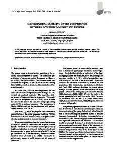
Fig. 3. Scanning electron micrograph of the calcareous deposits (top view) grown on low carbon steel rotating disk electrode in ASTM substitute ocean water at 50 rpm, -0.9 V(SCE), after 87 h.
[ Counter electrode
Fig. 1. Schematic of rotating disk electrode experimental cell. Figures 2 and 3 show the calcareous deposits grown at - 0 . 9 V (SCE) and 50 rpm after 40 and 87 h exposure, respectively. The cauliflower-like Crystals, growing on the metal base, are calcareous deposits. The elemental spectra analysis from SEM-EDAX for the calcareous deposits in Fig: 3 indicates that the main constituents in the calcareous deposits are Ca, C, and O as shown in Fig. 4. Also, Mg, Sr, Na, C1, S, and Fe are the trace elements found in the calcareous deposits. Detection of Fe might be due to the penetration of the electron beam to the underlying steel substrate. Figure 5 shows a side view of the calcareous deposit in Fig. 3. The white layer is the metal substrate. The top part shows the calcareous deposit with a thickness of about 10 ~m.
for the electrochemical reactions and consequently reduce the current density to the disk during CP. The proposed mechanism for the formation of calcareous deposits on cathodically protected steel in seawater is presented below. The calcareous deposits are assumed to be a mixture of CaCO3 and Mg(OH)2 in the model. A high concentration of OH- ions generated by the electrochemical reactions on the electrode surface causes the precipitation of Mg(OH)2 Mg 2++ 2 OH- --->Mg(OH)2$
Also, the production of OH- ions on the electrode surface changes-the inorganic carbon equilibria in the adjacent seawater and facilitates the following buffering reaction ~9
OH- + HC03 ~- H20 + CO~Ca 2 + CO~- --> CaCO~$
[6]
Equations are presented below that are used to describe transport phenomena, electrochemical reactions, precipitation reactions, and the homogeneous reaction involved in the formation of calcareous deposits on the electrode surface. The modeled region, as shown in Fig. 6, is the diffusion layer between y = 0 and y = YREand two boundaries at y = 0 and y = YR~,which represent the electrode surface and bulk solution interfaces, respectively. It is worth noting that the thickness of the deposits, about 10 #m as shown in Fig. 5, is much less than that of the diffusion layer, 150 ~m; consequently, the diffusion layer equations are used everywhere except at y = 0 and y = YR~
..................................................................
:.................................................................
":C ............... }................. "F - F ' - M ............. !
. . . . . . . . . . . . . . . . . . . . . . . . . . . . . . . . . . .
O.GIDO
Fig. 2. Scanning electron micrograph of the calcareous deposits (top view) grown on low carbon steel rotating disk eleclrode in ASTM substtue ocean water at 50 rpm, -0.9 V(SCE), after 40 h.
[5]
As a result, CaCO3 also precipitates
Model Development The experimental results indicate that the current density for CP decreases with time due to the formation of calcareous deposits, which is discussed further below, and our SEM pictures (see Fig. 2 and 3) show that the main change on the electrode surface is the increasing surface area covered by the calcareous deposits with no increasing thickness of the porous deposits. Therefore, the model presented in the following section is based on the fact that calcareous deposits block the active surface area available
[4]
i........................
i....................... ~y-"F
: ........................................................................
: .....
"-"''~ ......................... ....................... i............................
VFS
= 2048
10.:::'4~
Fig. 4. Scanning electron elemental spectra of the calcareous deposits [top layer) grown on low carbon steel rotating disk electrode
in ASTM substitute ocean water at 50 rpm, -0.9 VISCE), after 87 h.
Downloaded 18 Aug 2011 to 129.252.86.83. Redistribution subject to ECS license or copyright; see http://www.ecsdl.org/terms_use.jsp
J. Electrochem. Soc., Vol. 140, No. 3, March 1993 9 The Electrochemical Society, Inc.
735
Ao
H
I.--:-...'.'.1
I..-.:.1
Az
A3
AI
~
A,= At+ A~+ As
Ao
[X.X.X.X.X.X.X.X.X.]
A.
Fig. 5. Scanning electron micrograph of the calcareous deposits (side view) grown on low carbon steel rotating disk electrode in ASTM substitute ocean water at 50 rpm, -0.9 V(SCE), after 87 h.
0--m
Rotating Disk Electrode
D
Substrate
D
overed surface
y=O
T
A8
Ao
[ ~ Uncovered surface
Fig. 7. Schematic definition of surface coverage.
Calcareous deposits
A i is the surface area covered by calcareous deposits at time interval i. Surface coverage, by definition, increases with time, and equals 0.0 before the formation of the calcareous deposits and equals 1.0 when the surface is totally covered by the calcareous deposits. The deposit porosity is defined as the ratio of the total open volume inside the deposits (V~ - Vd) to the total volume of the porous deposits (V~) where
Y
Diffusion Layer
rcd -
vs - v d Vs
[8]
y=~,~ Bulk Solution
Fig. 6. Schematic of the electrode surface and the diffusion layer on a rotating disk electrode.
Before presenting the model equations, the following assumptions are made. 1. The electrolyte is isothermal. 2 . Dilute solution theory is applied. 3. Double-layer charging is neglected. 4. Electrochemical reactions occur only on the uncoated surface (i.e., the uncovered surface and the clean surface on the covered surface). 5. The reaction of iron, Eq. 1 can be neglected as long as the steel is under cathodic protection. 6. The precipitation reactions occur only on the uncovered surface. 7. The homogeneous reaction occurs in solution region. 8. Calcareous deposits are assumed to be a mixture of CaCO3 and Mg(OH)2. Also, they are assumed to be porous with constant porosity and thickness. 9. Deposits do not dissolve once they precipitate on the metal surface. 10. The nucleation process is neglected. Some parameters used in the model are defined as follows. Surface coverage 0 (see Fig. 7) is defined as the ratio of total surface area covered by porous deposits (As) to the total electrode surface area (Ao) 0 - ~Ai
As
Ao - Ao
[7]
where Vd is the volume occupied by the solid depOSits. By assuming that the deposit porosity and tortuosity of the porous layer are constant, the deposit porosity also can be expressed in terms of surface area ed =A s~ -Ad
- A~ ~
[9]
where Ad is the surface area occupied by solid deposits and Ap is the uncoated surface area inside the deposits. The surface porosity is then defined as the ratio of total bare surface area (,40- Ad) to the total electrode surface area (Ao) es Ao -- A d = A-o
[10]
It is worth noting that the difference between the deposit porosity and the surface porosity is that the former is based on the total surface area covered by porous deposits (As) and the latter is based on the total electrode surface area (A o). The definitions of ed and e~are compared schematically in Fig. 8. By making these definitions and assumptions, the current density is expected to approach to a steady state and nonzero value though the surface coverage is approaching 1.0. Together with the surface coverage, 0, and the solution potential, q~, the concentrations of nine components in seawater will be accounted for in the model. The 11 unknowns are numbered in the following way for notational convenience: 1, 02; 2, H2; 3, OH-; 4, Mg2~; 5, Ca2§ 6, CO~-; 7, HCO~; 8, Na§ 9, C1 ; 10, 0; and 11, r
Downloaded 18 Aug 2011 to 129.252.86.83. Redistribution subject to ECS license or copyright; see http://www.ecsdl.org/terms_use.jsp
J. Electrochem. Soc., Vol. 140, No. 3, March 1993 9 The Electrochemical Society, Inc.
736
Because there is no homogeneous reaction in the solution for species i = 1, 2, 4, 5, 8, and 9, the g o v e r n i n g e q u a t i o n becomes
AO
0ci_ Ot
I:::::::::"::':::::::::'::::::::::':l
A,
/
00 = 0 0y
A~
Aa
\ \
~s - Ao-A________d ~d Substrate Porous deposits
[19]
f=l
E q u a t i o n s 18 and 19 will be the governing equations for 0 and 9 in the diffusion layer. B o u n d a r y conditions on the electrode surface (y = O).-Instead of considering the actual geometric detail of porous structures, two parameters, MacMullin n u m b e r NM.p~ for porous layers and deposit porosity ed, are used to define the average quantities for c h a r a c t e r i z i n g the transfer p h e n o m ena in the porous layer. 22 The MacMullin n u m b e r is defined
A. Ao
[18]
f clzi = 0
\
A~
A I, A,
as '1"
IUncoated space N Solid deposits
N~.pE = --
[20]
Ed
Fig. 8. Schematic definitions of deposit porosity and surface porosity.
w h e r e v represents the tortuosity of the porous layer and is set to 1 a u t o m a t i c a l l y because the deposit thickness is ignored in the m o d e l e d region. The surface porosity es is t h e n defined as the s u m m a t i o n of the Open space in the u n c o v ered surface and the open space inside the covered surface e~ = (1 - 0) + Ca0
Governing equations in the diffusion layer (0 < y