MC Slicing for Volume Rendering Applications A. Benassarou1, E. Bittar1 , N. W. John2 , and L. Lucas1? 1
CReSTIC / LERI / MADS Universit´e de Reims Champagne-Ardenne, Reims, France 2 School of Informatics University of Wales, Bangor, United Kingdom
Abstract. Recent developments in volume visualization using standard graphics hardware provide an effective and interactive way to understand and interpret the data. Mainly based on 3d texture mapping, these hardware-accelerated visualization systems often use a cell-projection method based on a tetrahedral decomposition of volumes usually sampled as a regular lattice. On the contrary, the method we address in this paper considers the slicing problem as a restricted solution of the marching cubes algorithm [1, 2]. Our solution is thus simple, elegant and fast. The nature of the intersection polygons provides us with the opportunity to retain only 4 of the 15 canonical configurations defined by Lorensen and Cline and to propose a special look-up table.
1
Introduction
Interactivity is often regarded as a necessary condition to efficiently analyze volumetric data, and so obtaining fast enough rendering speeds has historically been a major problem in volume visualization systems. Over the last decade, a large number of methods have been developed to significantly improve traditional approaches, which are known to be very expensive with respect to CPU usage [3]. The generalized use of modern PC graphics boards is part of these recent advances to offer today’s users a good level of interactivity [4–6]. The volume rendering algorithm that we have developed employs a novel technique that is centered on an efficient incremental slicing method derived from the marching cubes algorithm [1, 2]. This approach allows us to achieve interactive rendering on structured grids on standard rendering hardware. In this paper we present a brief overview of related work (Sec. 2), and review the basic concepts of direct volume rendering via 3d texture mapping (Sec. 3). We then describe in detail our incremental slicing algorithm together with an analysis of the results that we have obtained from our visualization system.
2
Background and related work
The two main categories of volume visualization techniques in popular use are surface extraction algorithms and direct volume rendering algorithms. The key ?
Correspondence to:
[email protected], Rue des Cray`eres, BP 1035, 51687 Reims Cedex 2.
idea of surface-based rendering is to extract an intermediate surface description of the relevant objects from the volume data [2]. In volume rendering, images are created directly from the volume data, and no intermediate geometry is extracted [7]. Our work is concerned with this second category, and in particular, with interactive volume rendering methods. Note, however, that we will make use of a technique first developed for the marching cubes surface-based rendering algorithm. A variety of software and hardware approaches are possible to implement direct volume rendering. They will typically employ one of two basic scanning strategies for traversing the volume: Feed Backward Projection or Image Order Traversal. The pixels in the image plane are traversed and imaginary rays are cast through each pixel in the volume. The path of the ray determines the pixel value. Lavoy’s raycasting algorithm is an example of image order traversal. Feed Forward Projection or Object Order Traversal. The data volume is traversed and each voxel in the volume is projected onto the image plane. Splatting [8] is a good example of an Object Order Traversal technique. These strategies correspond to the image and object order rasterization algorithms. High quality volume rendering, at the cost of compute time, is provided by raycasting and splatting; lower quality, but faster rendering, is provided by shear-warp rendering [9] and texture-based methods. These faster methods will typically make use of graphics hardware to provide interactive rendering rates, and the latest generations of commodity graphics cards, such as NVidia GeForce and ATI Radeon families, are proving to be ideal for this purpose. In the following sections, we have classified algorithms that make use of commodity graphics cards into: projection-based methods and slicing-based methods. We then provide an overview of texture mapping methods for volume rendering. Projection-based methods. Shirley and Tuchman [10] were amongst the first to use polygon rendering hardware support for approximate volume rendering. Based on a decomposition into tetrahedra of any part of three-dimensional data, the projected tetrahedra (PT) algorithm proceeds first by classifying each tetrahedron according to its projected profile in order to find the positions of the tetrahedra vertices after the perspective transformation and to decompose them into triangles. This idea of the PT algorithm has subsequently been re-used by many similar works since then. For example, Stein et al. [11] attempted to improve these approximations by employing a more accurate sorting algorithm. Slicing-based methods. Slicing-based methods can be considered as an approximation of the previous methods, whereby the projections of the faces of a polyhedral element are approximated by a set of polygons. Yagel et al. [12] proposed a technique that allows the faces to be approximated by a polygon that represents its intersection with a sweep plane. They show that this technique can render visually comparable images faster without having to explicitly store any kind of vertex or face adjacency information which is necessary for most other
methods. Other proxy geometry, such as spherical shells, may be used to eliminate artifacts caused by perspective projection [13]. More recently, Chopra and Meyer [14] have improved Yagel’s incremental slicing method whereas Lensch et al. [15] have proposed a new paradigm based upon a slicing prism.
3
Slicing-based methods for hardware texture mapping
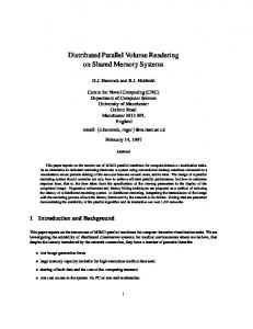
The OpenGL application programming interface provides access to the advanced per-pixel operations that can be applied at the rasterization stage of the graphics pipeline, and in the frame buffer hardware of modern graphics workstations. In particular, they provide sufficient power to render high resolution volume data sets with interactive frame rate using 2d or 3d texture mapping. Object-aligned slicing. Support for 2d texture mapping is now a standard feature of modern graphics PCs, and is suitable for implementing object-aligned slicing. The principle is similar to the shear-warp algorithm [9]. It involves storing a set of three rectilinear volume data sets, and using them as three perpendicular stacks of object aligned texture slices (Fig. 1). Slices are taken through the volume orthogonal to each of the principal axes and the resulting information for each slice is represented as a 2d texture that is then pasted onto a square polygon of the same size. The rendering is performed by projecting the textured quads and blending them back-to-front into the frame buffer. During the process of texture mapping the volume data is bilinearly interpolated onto a slice polygon.
Fig. 1. Object-aligned slice stacks with 2d texture mapping.
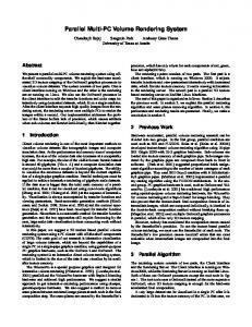
View-aligned slicing. The use of 3d texture mapping hardware has become a powerful visualization option for interactive high-quality direct volume rendering [16, 6]. The rectilinear volume data is first converted to a 3d texture. Then, a number of planes perpendicular to the viewer’s line of sight are clipped against the volume bounding box. The texture coordinates in parametric object space are assigned to each vertex of the clipped polygons. During rasterization, fragments in the slice are trilinearly interpolated from 3d texture and projected onto the image plane using adequate blending operations (Fig. 2).
Fig. 2. View-aligned slice stacks with 3d texture mapping.
Proxy geometry characterization. The proxy geometry characterization step in the graphical pipeline can be specified by either enclosing rectangles of intersections, or polygons of intersections. The use of enclosing rectangles is a straightforward method of texture mapping cut-planes. Other approaches are more complex and require finding the polygon of intersection between a given cut-plane and the cube of data. Directly performed on the CPU or the GPU, this approach is faster for processing fragments, because one visits only those fragments that are inside the cube of data. The approach used by Kniss et al. [17] considers the following stages: 1. Transform the volume bounding box vertices into view coordinates. 2. Find the minimum and maximum z coordinates of the transformed vertices. 3. For each plane, in back-to-front order: (a) Test for intersections with the edges of the bounding box and add each intersection point (up to six) to a fixed-size temporary vertex list. (b) Compute the centre of the proxy polygon by averaging the intersection points and sort the polygon vertices clockwise [18]. (c) Tessellate the proxy polygon into triangles and add the resulting vertices to the output vertex array. Unfortunately, this algorithm suffers from its re-ordering stage. Conversely, the method we propose provides an implicitly ordered sequence of vertices that can be directly drawn by OpenGL function calls. This novel, easy to use algorithm is described below.
4
MC slicing algorithm.
Marching cubes principle. Concisely, the original marching cubes algorithm allows one to efficiently polygonize an approximation of the intersection between a surface and a cube. The approximation is achieved through evaluating some predicate at the eight corners of the cube. The 256 possible solutions are known and stored in a precalculated table. Each entry of this table is a triplet sequence which indicates the edges hit by the surface and allows us to interpolate the intersection triangles.
Adjustments for slicing purposes. In our case, we have a singular surface and a single cube. The surface is a view-aligned plane, and the cube is the 3d texture. The predicate we test on each corner of this unit cube is defined as follows: “Is this corner deeper than the current plane?” (Algo. 1, line 1). When the intersection between the cube and the plane is not empty (0 vertex), it is either a triangle (3 vertices), a quad (4), a pentagon (5) or a hexagon (6). As there is never more than one connected component, the 256 surfaces might be stored directly as polygons (Table 1) instead of triangle sets. In fact, these polygons are all convex and they can even be transmitted to OpenGL as triangle fans.
Algorithm 1: McSliceCube () begin for i ∈ [0 . . . 8[ do Zi = (i&1 6= 0 ? GL MODELVIEW0,2 : 0) + (i&2 6= 0 ? GL MODELVIEW1,2 : 0) + (i&4 6= 0 ? GL MODELVIEW2,2 : 0) + GL MODELVIEW3,2 ;
1
2 3 4 5
zmin = mini∈[0...8] (Zi ); zmax = maxi∈[0...8] (Zi ); for z ∈ [zmin P . . . zmax ] do key = i∈[0...8[ (Zi > z ? 2i : 0); if Tkey,0 6= −1 then glBegin (GL TRIANGLE FAN); McSliceEdge (Z, z, Tkey,0 ); McSliceEdge (Z, z, Tkey,1 ); McSliceEdge (Z, z, Tkey,2 ); for (i = 3; Tkey,i 6= −1; i = i + 1) do McSliceEdge (Z, z, Tkey,i ); glEnd (); end
Algorithm 2: McSliceEdge (Z, z, e) // Vertices + coordinates of an edge edge v0, edge v1 : EdgeId 7→ V ertexId edge x, edge y, edge z : EdgeId 7→ ∅ ∪ {0, 1} begin z0 = Z[v0 ] where v0 = z1 = Z[v1 ] where v1 = r = (z − z0 )/(z1 − z0 ); switch e do case 0, 1, 2, 3 case 4, 5, 6, 7 case 8, 9, 10, 11 end
edge v0 (e); edge v1 (e);
: glVertex3d (r, edge y (e), edge z (e)); : glVertex3d (edge x (e), r, edge z (e)); : glVertex3d (edge x (e), edge y (e), r);
zmin
Screen v6
zmax
Y v2
e9 e3
v7
Depth
e8
Eye Z
v4 e1
v3 v1
v5
X
Slice
Fig. 3. Example of MC slicing. Vertices 0, 1, 2, 3, 5 and 7 are deeper than the slicing plane.
T intersected edge sequence 0 -1, -1, -1, -1, -1, -1, -1, -1 1 4, 8, 0, -1, -1, -1, -1, -1 .. .. . . 174 1, 3, 9, 4, 0, -1, 175 3, 9, 8, 1, -1, -1, 176 3, 11, 10, 8, 5, -1, .. .. . . 254 4, 0, 8, -1, -1, -1, 255 -1, -1, -1, -1, -1, -1,
-1, -1 -1, -1 -1, -1 -1, -1 -1, -1
Table 1. Excerpt from our table. Each entry is an ordered sequence of edges hit by the surface.
Example. If we consider the case seen in Fig. 3, we observe that six vertices are deeper than the current cut plane. Those vertices are named 0, 1, 2, 3, 5 and 7. Line 1 of Algo. 1 gives 1 + 2 + 4 + 8 + 32 + 128 = 175 as index of the first dimension of Table 1. At this index, we find that the ordered sequence T175 = {3, 9, 8, 1, −1, −1, −1, −1}, which means that the intersection is not empty (T175,0 6= −1) and the first edge to be processed is edge number 3 (T175,0 ). Line 2 calls Algo. 2 which performs the intersection for this edge (interpolation between the two ends of the edge, v6 and v7 ). Similarly, lines 3 and 4 compute the intersection points with edges 9 (T175,1 ) and 8 (T175,2 ). Because there is a fourth edge (T175,3 6= −1), we then enter the loop and finally operate line 5 (edge 1). The algorithm ends the triangle fan here since T175,4 = −1.
Fig. 4. Comparisons between our methods and the usual Convex hull approach.
5
Results and discussion
For comparison purposes, we have implemented the usual Convex hull solution (Sec. 3). We have also developed a marching tetrahedra-like algorithm. Whereas MC slicing operates directly on a cube, MT slicing decomposes the same cube into six tetrahedra and computes the intersection between the slicing plane and each tetrahedron. There are fewer cases (16 instead of 256) and intersections are either triangles or quads when they exist. The main advantage offered by the original marching tetrahedra is that the resulting geometry does not suffer from the possible ambiguities of the marching cubes. Nevertheless, the simplicial decomposition involves more OpenGL primitives as we compute six intersections instead of one. Because there cannot be any ambiguity when intersecting a plane and a cube, we consider that the extra computational cost is not really worth it. Figure 4 presents the comparison between the three discussed methods. The performance measurements were obtained on a Linux platform equipped with an AMD Athlon XP 2200+ CPU and a GeForce 6800 TD graphic board using a viewport size of 704 × 576 pixels. The volume data (512 × 512 × 106 CT scan) is illustrated on Fig. 2. Each technique has been run five times at five different sampling rates : 1×, 2×, 4×, 8× and 16× (distance between slices = 1/16). Algorithm 2 has also been coded with shading languages such as Cg or GLSL but we did not notice any real gain. The benchmarks present the number of frames per second reached without and with actual texturing process. We observe that, at low sampling rates, our method shortly accelerates the rendering. The real impact of our method can be observed with higher sampling rates: from 4× to 16×, the MC algorithm performs the same slicing as the other two approximately four and five times quicker. This major improvement in the performance is mainly due to the simplicity of the algorithm. Like the original marching cubes, our method owes its efficiency to the precalculation of a 2 Kbytes look-up table. In summary, the two major advantages of the MC slicing approach are: it processes the whole cube without any tetrahedral decomposition; and it generates the surface vertices directly in the correct order. These advantages allow us to save on the CPU time and to achieve higher frame rates.
6
Conclusion
In this paper, we presented an accelerated slicing algorithm for interactive volume rendering of structured grids. Derived from the classic marching cubes, it requires a small amount of memory and provides adaptive rendering for improved image accuracy as well as progressive rendering for rapid feedback at interaction time. It is finally suited to exploit graphics hardware. There is a growing requirement for interactive volume visualization from medical applications. Collaborative work is beginning on developing a virtual reality simulator for interventional radiology procedures [19], where fast and efficient rendering of patient specific data is a major requirement. We intend using the MC slicing algorithm to provide this requirement. This will enable us to further develop and refine the ideas presented in this paper.
References 1. Wyvill, B., Wyvill, G., McPheeters, C.: Data structure for soft objects. The Visual Computer 2 (1986) 227–234 2. Lorensen, W., Cline, H.: Marching cubes : a high resolution 3D surface construction algorithm. Computer Graphics 21 (1987) 163–169 3. Brodlie, K., Wood, J.: Recent advances in visualization of volumetric data. In: Proc. Eurographics 2000 - STAR Reports. (2000) 65–84 4. Engel, K., Ertl, T.: High-quality volume rendering with flexible consumer graphics hardware. In: Proc. Eurographics ’02 - STAR Reports. (2002) 5. Roettger, S., Guthe, S., Weiskopf, D., Ertl, T., Strasser, W.: Smart hardware accelerated volume rendering. In: Proc. Eurographics/IEEE TCVG Symposium on Visualization. (2003) 231–238 6. Westermann, R., Ertl, T.: Efficiently using graphics hardware in volume rendering applications. Computer Graphics 32 (1998) 169–179 7. Levoy, M.: Display of surfaces from volume data. IEEE Computer Graphics and Applications 8 (1988) 29–37 8. Westover, L.: Footprint evaluation for volume rendering. Computer Graphics 24 (1991) 9. Lacroute, P., Levoy, M.: Fast volume rendering using a shear-warp factorization of the viewing transformation. Computer Graphics 28 (1994) 451–458 10. Shirley, P., Tuchman, A.: A polygonal approximation to direct scalar volume rendering. Computer Graphics 24 (1990) 63–70 11. Stein, C., Becker, B., Max, N.: Sorting and hardware assisted rendering for volume visualization. In: Proc. ACM Symposium on Volume Visualization. (1994) 83–90 12. Yagel, R., Reed, D., Law, A., Shih, P., Shareef, N.: Hardware assisted volume rendering of unstructured grids by incremental slicing. In: Proc. ACM Symposium on Volume Visualization ’96. (1996) 55–63 13. LaMar, E., Hamann, B., Joy, K.: Multiresolution techniques for interactive texturebased volume visualization. In: Proc. ACM Symposium on Volume Visualization ’99. (1999) 355–361 14. Chopra, P., Meyer, J.: Incremental slicing revisited: Accelerated volume rendering of unstructured meshes. In: Proc. IASTED Visualization, Imaging and Image Processing ’02. (2002) 533–538 15. Lensch, H., Daubert, K., Seidel, H.: Interactive semi-transparent volumetric textures. In: Proc. Vision, Modeling and Visualization ’02. (2002) 505–512 16. Cabral, B., Cam, N., Foran, J.: Accelerated volume rendering and tomographic reconstruction using texture mapping hardware. In: Proc. ACM Symposium on Volume Visualization ’94. (1994) 91–98 17. Kniss, J., Kindlmann, G., Hansen, C.: Interactive volume rendering using multidimensional transfer functions and direct manipulation widgets. In: Proc. Visualization ’01. (2001) 255–262 18. Moret, B., Shapiro, H.: Algorithms from P to NP. Volume I: Design and Efficiency. Benjamin-Cummings (1991) 19. Healey, A., Evans, J., Murphy, M., Gould, D., Phillips, R., Ward, J., John, N., Brodlie, K., Bulpit, A., Chalmers, N., Groves, D., Hatfield, F., How, T., Diaz, B., Farrell, M., Kessel, D., Bello, F.: Challenges realising effective radiological interventional virtual environments: the CRaIVE approach. In: Proc. Medicine meets Virtual Reality, IOS Press (2004) 127–129